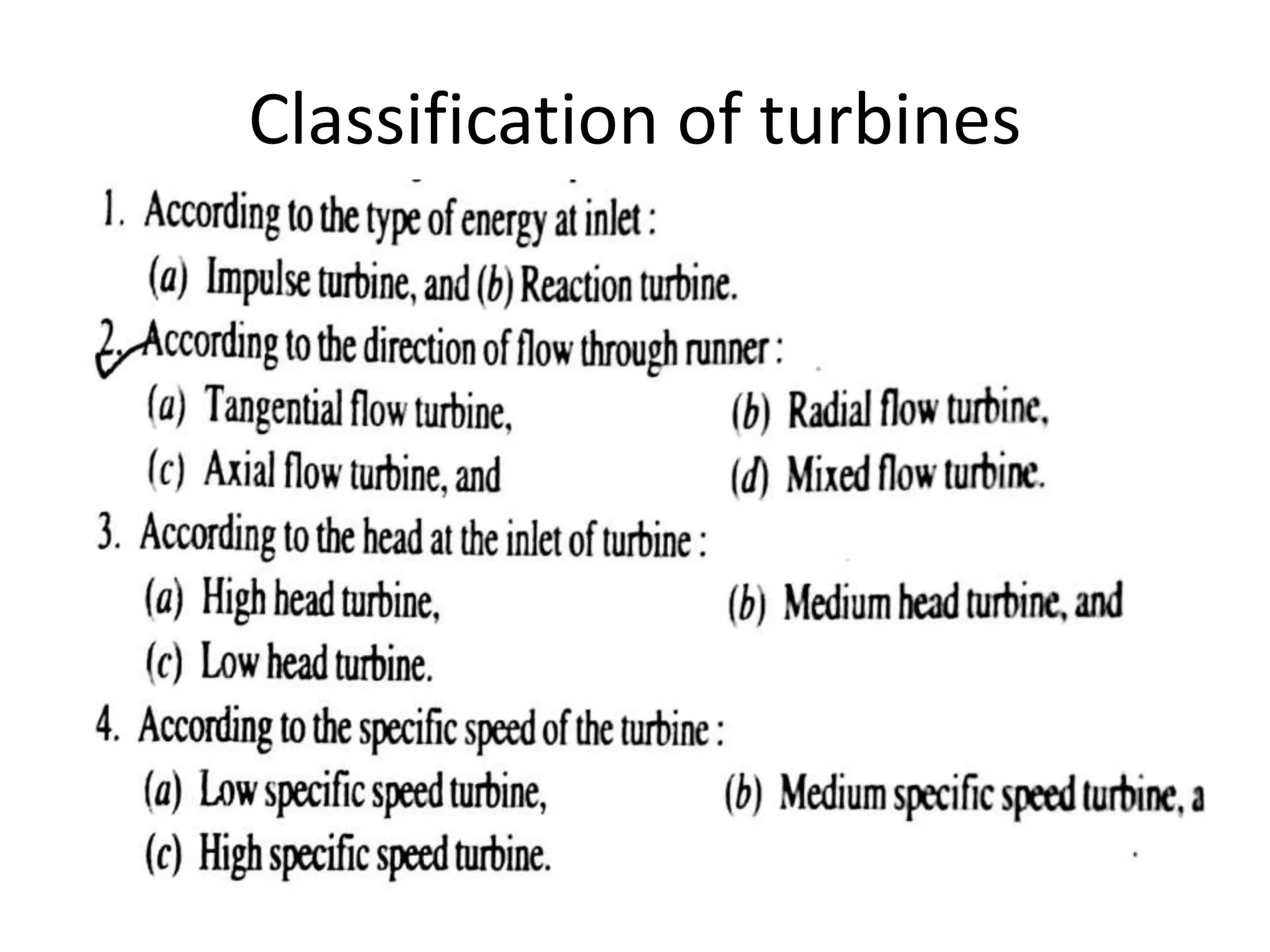
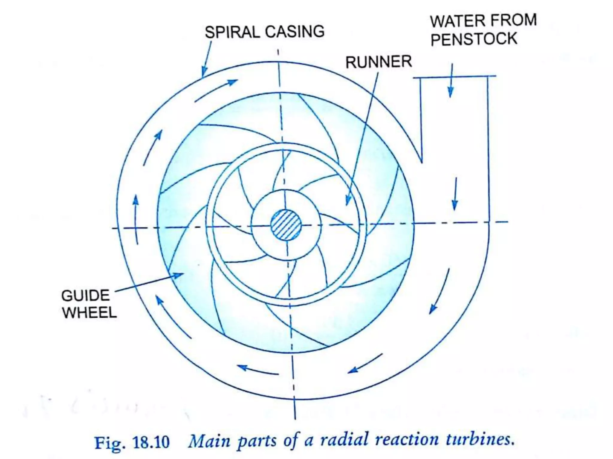
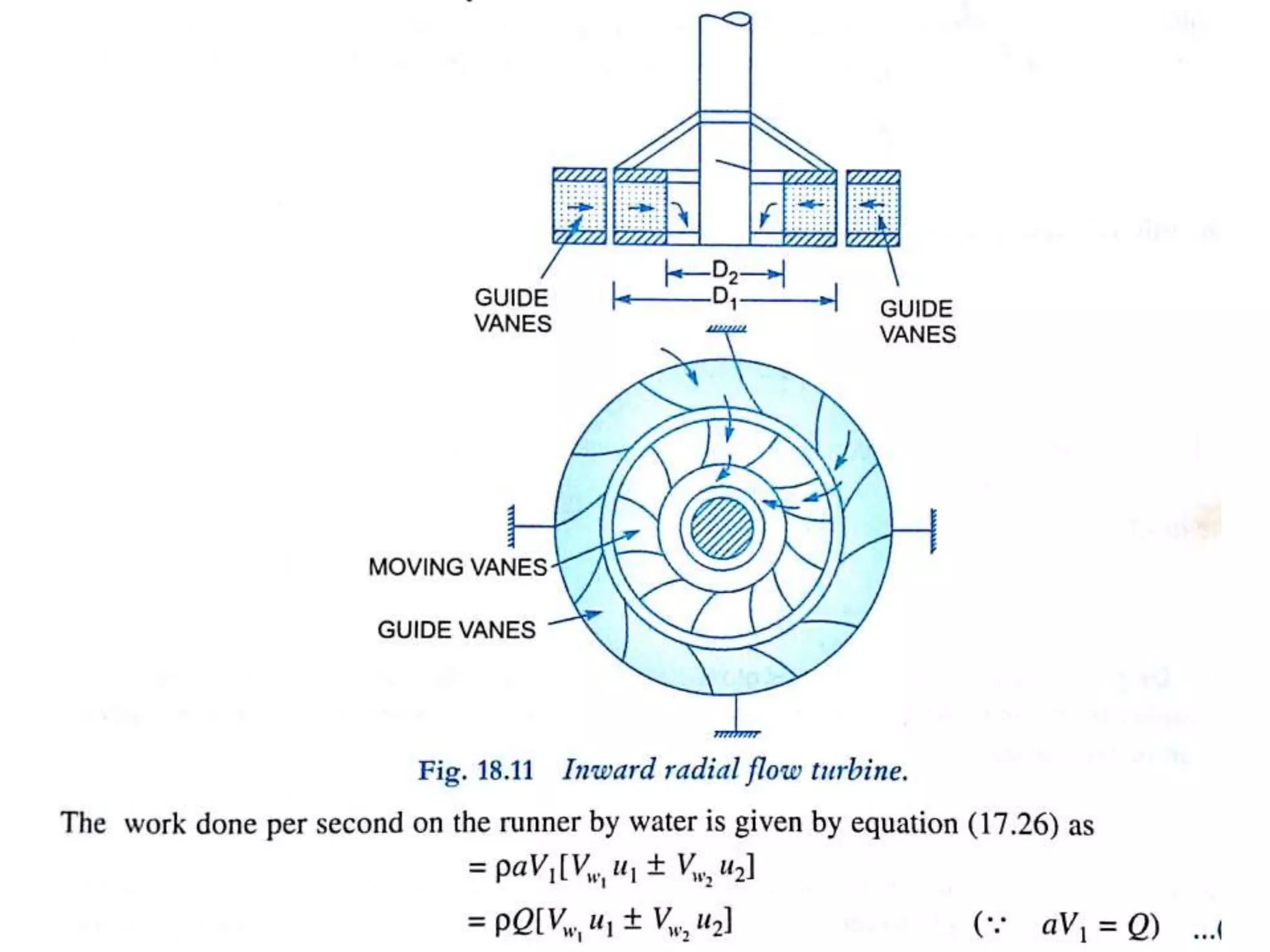
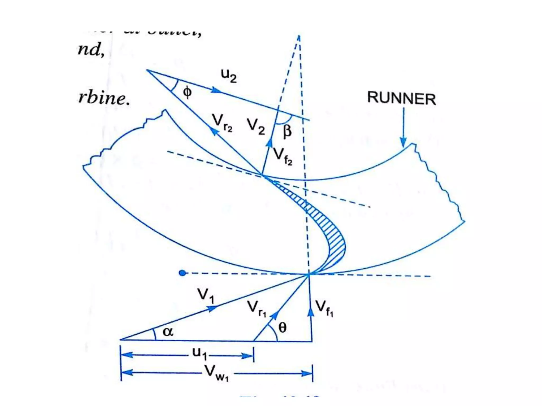
UNIT-V
TURBINES
Unit-5
TURBINE
Classification of turbines
Nozzle
Velocity diagram
SPLITTER
BUCKETSORVANES
RUNNER
15
PELTON WHEEL
..(5)
•At
FRANCIS TURBINE
• Named after American Engineer
J.B.Francis
• It is a mixed flow reaction turbine with
medium head and medium specific speed
• Penstock
• Scroll/Spiral casing
• Speed ring/Stay ring
• Stay vanes
• Guide vanes/Wicket vane
• Runner blades
• Draft tube
• Water from the penstock enters the scroll casing which
completely surrounds the runner.
• Involute casing provides an even distribution of
water(constant velocity) around the circumference of the
runner.
• Stay rings directs water from scroll casing to guide vanes.
• The guide vanes
• -regulate the quantity of water supplied tothe
runner(to take care of the load variations)
• -direct water to the runner at an appropriate angle.
• The runner consists of a series of curved vanes evenly
arranged around the circumference.
• The difference in pressure between the inlet and
• outlet of the runner is called reaction pressure.
• Water enters the runner from the guide vanes towards the centre
radially and discharges out axially- Mixed flow turbine.
• After doing work water is discharged to the tail race through a
closed tube of gradually enlarging section called draft tube.
• As water flows through the runner the change from pressure to
kinetic energy takes place gradually.
• At the entrance to the runner only a part of energy of water is
converted into kinetic energy and substantial part remains in the
form of pressure energy.
FRANCIS TURBINE …3
KAPLAN TURBINE
• Developed by Austrian Engineer
• V. Kaplan.
• Suitable for relatively low heads and requires
large volume of water to develop large power.
• Kaplan turbine is a reaction turbine in which
water enters and leaves the runner blades
axially-Axial flow turbine
• The shaft of an axial flow reaction turbine is
vertical.
• The lower end of the shaft is made bigger and is
known as hub or boss.
• The runner vanes are fixed on the hub or boss.
• Kaplan turbine works on the reaction principle as
Francis turbine.
• Only difference is that water enters and leaves
the turbine axially – Axial flow turbine.
• Both the guide vane(wicket gate) angle and
runner vane angle can be adjusted which gives
rise to high efficiency.
KAPLAN TURBINE …1
GOVERNING OF PELTON WHEEL

FMM- UNIT V TURBINES

  • 1.
  • 2.
  • 4.
  • 6.
  • 7.
  • 8.
  • 9.
  • 11.
  • 12.
    • Named afterAmerican Engineer J.B.Francis • It is a mixed flow reaction turbine with medium head and medium specific speed • Penstock • Scroll/Spiral casing • Speed ring/Stay ring • Stay vanes • Guide vanes/Wicket vane • Runner blades • Draft tube
  • 13.
    • Water fromthe penstock enters the scroll casing which completely surrounds the runner. • Involute casing provides an even distribution of water(constant velocity) around the circumference of the runner. • Stay rings directs water from scroll casing to guide vanes. • The guide vanes • -regulate the quantity of water supplied tothe runner(to take care of the load variations) • -direct water to the runner at an appropriate angle. • The runner consists of a series of curved vanes evenly arranged around the circumference.
  • 14.
    • The differencein pressure between the inlet and • outlet of the runner is called reaction pressure. • Water enters the runner from the guide vanes towards the centre radially and discharges out axially- Mixed flow turbine. • After doing work water is discharged to the tail race through a closed tube of gradually enlarging section called draft tube. • As water flows through the runner the change from pressure to kinetic energy takes place gradually. • At the entrance to the runner only a part of energy of water is converted into kinetic energy and substantial part remains in the form of pressure energy.
  • 15.
  • 20.
    KAPLAN TURBINE • Developedby Austrian Engineer • V. Kaplan. • Suitable for relatively low heads and requires large volume of water to develop large power. • Kaplan turbine is a reaction turbine in which water enters and leaves the runner blades axially-Axial flow turbine
  • 24.
    • The shaftof an axial flow reaction turbine is vertical. • The lower end of the shaft is made bigger and is known as hub or boss. • The runner vanes are fixed on the hub or boss. • Kaplan turbine works on the reaction principle as Francis turbine. • Only difference is that water enters and leaves the turbine axially – Axial flow turbine. • Both the guide vane(wicket gate) angle and runner vane angle can be adjusted which gives rise to high efficiency.
  • 25.
  • 28.