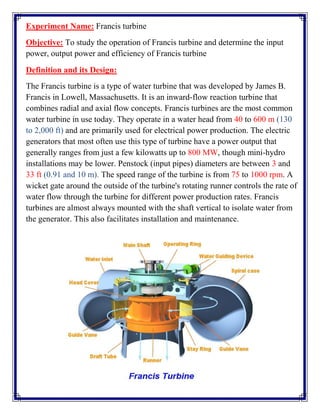
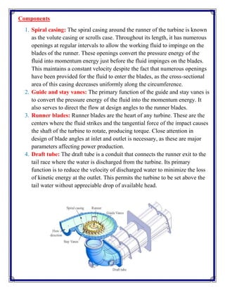
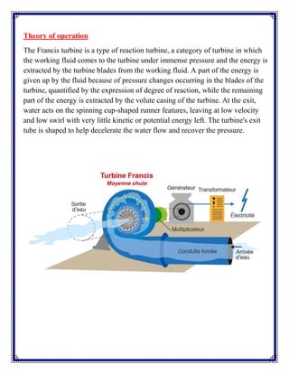
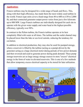
Sheet Pile Wall Design and Construction: A Practical Guide for Civil Engineer...
Francis turbine
1. Experiment Name: Francis turbine
Objective: To study the operation of Francis turbine and determine the input
power, output power and efficiency of Francis turbine
Definition and its Design:
The Francis turbine is a type of water turbine that was developed by James B.
Francis in Lowell, Massachusetts. It is an inward-flow reaction turbine that
combines radial and axial flow concepts. Francis turbines are the most common
water turbine in use today. They operate in a water head from 40 to 600 m (130
to 2,000 ft) and are primarily used for electrical power production. The electric
generators that most often use this type of turbine have a power output that
generally ranges from just a few kilowatts up to 800 MW, though mini-hydro
installations may be lower. Penstock (input pipes) diameters are between 3 and
33 ft (0.91 and 10 m). The speed range of the turbine is from 75 to 1000 rpm. A
wicket gate around the outside of the turbine's rotating runner controls the rate of
water flow through the turbine for different power production rates. Francis
turbines are almost always mounted with the shaft vertical to isolate water from
the generator. This also facilitates installation and maintenance.
2. Components
1. Spiral casing: The spiral casing around the runner of the turbine is known
as the volute casing or scrolls case. Throughout its length, it has numerous
openings at regular intervals to allow the working fluid to impinge on the
blades of the runner. These openings convert the pressure energy of the
fluid into momentum energy just before the fluid impinges on the blades.
This maintains a constant velocity despite the fact that numerous openings
have been provided for the fluid to enter the blades, as the cross-sectional
area of this casing decreases uniformly along the circumference.
2. Guide and stay vanes: The primary function of the guide and stay vanes is
to convert the pressure energy of the fluid into the momentum energy. It
also serves to direct the flow at design angles to the runner blades.
3. Runner blades: Runner blades are the heart of any turbine. These are the
centers where the fluid strikes and the tangential force of the impact causes
the shaft of the turbine to rotate, producing torque. Close attention in
design of blade angles at inlet and outlet is necessary, as these are major
parameters affecting power production.
4. Draft tube: The draft tube is a conduit that connects the runner exit to the
tail race where the water is discharged from the turbine. Its primary
function is to reduce the velocity of discharged water to minimize the loss
of kinetic energy at the outlet. This permits the turbine to be set above the
tail water without appreciable drop of available head.
3. Theory of operation
The Francis turbine is a type of reaction turbine, a category of turbine in which
the working fluid comes to the turbine under immense pressure and the energy is
extracted by the turbine blades from the working fluid. A part of the energy is
given up by the fluid because of pressure changes occurring in the blades of the
turbine, quantified by the expression of degree of reaction, while the remaining
part of the energy is extracted by the volute casing of the turbine. At the exit,
water acts on the spinning cup-shaped runner features, leaving at low velocity
and low swirl with very little kinetic or potential energy left. The turbine's exit
tube is shaped to help decelerate the water flow and recover the pressure.
4. Application:
Francis turbines may be designed for a wide range of heads and flows. This,
along with their high efficiency, has made them the most widely used turbine in
the world. Francis type units cover a head range from 40 to 600 m (130 to 2,000
ft), and their connected generator output power varies from just a few kilowatts
up to 800 MW. Large Francis turbines are individually designed for each site to
operate with the given water supply and water head at the highest possible
efficiency, typically over 90%.
In contrast to the Pelton turbine, the Francis turbine operates at its best
completely filled with water at all times. The turbine and the outlet channel may
be placed lower than the lake or sea level outside, reducing the tendency for
cavitation.
In addition to electrical production, they may also be used for pumped storage,
where a reservoir is filled by the turbine (acting as a pump) driven by the
generator acting as a large electrical motor during periods of low power demand,
and then reversed and used to generate power during peak demand. These pump
storage reservoirs act as large energy storage sources to store "excess" electrical
energy in the form of water in elevated reservoirs. This is one of a few methods
that allow temporary excess electrical capacity to be stored for later utilization.