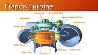
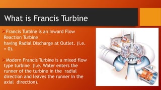
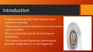
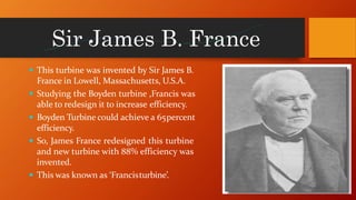
Group Members:
 K M Nazmus Sakib 15207013
 Md. Shakir Alom 15207014
 Ariful Islam 15207016
 Md sujon Babu 15207019
 Md Rashidul Islam 15207021
Group Number-05
Contents
• Basic Types of Turbine
• What is Francis Turbine
• Introduction of Francis Turbine
• Types of Francis Turbine
• Main Parts of Francis Turbine
• WorkingofFrancisTurbine
• Efficiencies of Francis Turbine
• Advantages
• Disadvantages
• Recent Advancements
• Application of Francis
Turbine
• How can we make it
Economical
• Conclusion
Basic Types of Turbine
Steam Turbine
WaterTurbine
Wind Turbine
Gas Turbine
Types Based Energy Used
 Impulse turbine :
Only kinetic energy of water is used to drive
turbine.
Eg. Pelton Turbine
 Reaction turbine:
Kinetic energy as well as Pressure energy of water
is used todrive turbine.
Eg.Francis Turbine
Francis Turbine is an Inward Flow
Reaction Turbine
having Radial Discharge at Outlet. (i.e.
= 0).
Modern Francis Turbine is a mixed flow
type turbine (i.e. Water enters the
runner of the turbine in the radial
direction and leaves the runner in the
axial direction).
What is Francis Turbine
Introduction
 Francis turbines are the most common water
turbine in usetoday.
 Theyoperate in a water head from 10 to 650 meters
(33 to 2,133 feet).
 Theyare primarily used forelectrical power
production.
 The turbine powered generator poweroutput
generally ranges from 10 to 750 megawatts
Md. Shakir Alom
Sir James B. France
 This turbine was invented by Sir James B.
France in Lowell, Massachusetts, U.S.A.
 Studying the Boyden turbine ,Francis was
able to redesign it to increase efficiency.
 Boyden Turbine could achieve a 65percent
efficiency.
 So, James France redesigned this turbine
and new turbine with 88% efficiency was
invented.
 This was known as ‘Francisturbine’.
Types of Francis Turbine
There are basic two types of Francis turbines according to the flow of water.
Radial flow Francis Turbines:
In this type of Francis turbine, water enters radially.
This means the flow at entry is tangential to the runner.
The water enters through guide vanes and then directed to
runner blade. This type of design normally has less efficiency
as compared to mixed or axial flow type. Normally they are
designed for small - medium scale hydropower plants
Cont….
Mixed Flow Francis Turbines:
In this type of turbine, the flow is directed in an angle between
radial and axial. As per requirement a mixed flow Francis can
be designed as reversible machine which can be used as pump.
Turbines designed for radial flow normally has lesser flow rate
than turbines that are designed for axial flow. Hence, the
turbine speed increases and the increment in the shaft output
power is achieved.
Penstock-It is a large size conduit which conveys
water from upstream to the dam/reservoir to the
turbine runner
spiral casing- It constitutes a closed passage whose
cross section area gradually decrease along flow
direction area is maximum at inlet and nearly zero at
exit.
guide vanes-These vanes direct the water on the
runner at an angle appropriate to the design,
controlled by hand wheel or governor
Main Parts of Francis Turbine
Main Parts
Governing mechanism- It changes the position of
guide vanes to affect a variation in water flow rate, when the load
condition on the turbine changes
Runner and runner blades- The driving force on the runner is both due
to impulse and reaction effect(usually runner blades 16-24).
Draft tube- It is generally an expending tube which discharges the
water, passing through the runner to the tail race.
Md. Ariful Islam
In the Francis turbines the water must be
enter into
inlet nozzle and the velocity must be
decreases.
Then the water moves in the forward
direction in the turbine but continuous
decrease in the spiral casing area must be
happened. With the constant speed the
water strikes the turbine blades.
So the motion takes place from the high pressure to
the low pressure.
Inside the blade it looks like a bucket it using the impulsive
force for rotation of water.
On the runner the blades are mounted. The blades are designed
like a thin air foil.
Cont……
Cont……
If the flow rate of water changes then by using the governing
mechanism we can set the angle of attack of the water on the
blade. At that case the turbine works properly.
Initially the water passes from the blades and next later enters
into the draft tube, where we can notice the continuous increment
in the area and velocity of the water must be decreases.
So due to the design the water flow occurs at low pressure at one
point and other side it creates a low pressure.
Efficiencies of Francis Turbine
Hydraulic Efficiency - It is ratio of power developed by the
runner of a turbine to the power supplied by the water at the inlet.
Power developed by the runner
Power available at the inlet
ηh =
Mechanical Efficiency – It is ratio of power available at the shaft
to power developed at the runner.
Power at the shaft of the turbine
ηm =
Power developed by the runner
• Volumetric Efficiency - It is ratio of volume of the water
actually striking the runner to the volume of water supplied to the
turbine.
• Volumetric efficiency (η) =
volume of water striking the bucket
volume of water supplied to the turbine
• Overall Efficiency - It is ratio of power available at the shaft of
the turbine to the power supplied by the water at the inlet of the
turbine.
• Overall efficiency ( η ) = Power available to the shaft
Power suppied at the inlet
Cont……
Md. Sujon Babu
Advantages
 It is a mostwidely used turbine in world (about 70- 80%).
 Effectiveuse of waterpressure as well as velocity.
 It is American standardturbine.
 Very good efficiency(80-94%).
Disadvantages
• Its cost is very high.
• Its operation is simple but the design is very complex.
• Large number of moving parts are present.
• Its maintenance and repair is difficult task and expensive too.
• It is applicable to medium head levels only.
• Cavitation is also a big problem.
Recent Advancements:
 New typesof designs aredeveloped to reducecostand complexity
of mechanism.
 Modified turbine include Inline LinklessFrancis Turbine,
Cross-flowTurbine,etc.
 These new turbine require less space, simplified designs,
less moving parts,etc.
Problem:
A Francis’ 135 kW turbine, having an overall efficiency of 75%, is required to
produce under a head of 9 meter and at 120 r.p.m. The velocity of
periphery of the wheel and velocity of flow at inlet is 3.47√H and 1.1√H
respectively. If the hydraulic losses in the turbine are 20% of the available
energy, find:
a) Guide blade angle at inlet,
b) Wheel vane angle at inlet, and
c) Diameter of the wheel.
Md. Rashidul Islam
 At first, F.turbine was used in industries to drive the machines via
belts.
 Used to pump the water up when there is not much electricity
needed.
 It is used in dams and water reservoirs to generate
hydroelectric power.
Application
Another big application of Francis turbine is
Itaipu Dam in Brazil.
• Located on the Parana River between Brazil and Paraguay.
• One of the Seven Wonders of the Modern World.
• Second largest hydroelectric power plant.
• 87.8 TWh generated in 2014.
• 118m of hydraulic head.
• 20 Francis turbines.
700 MW each
We use New types of designs to reduce the cost and complexity of
mechanism.
 Modified turbine include lnline Link less Francis turbine, Cross flow
turbine
 These new turbine require less space, simplified designed , less moving
parts, etc.
Conclusions
• Francis turbines are one of the most widely used turbines of our
time .
• Extremely high efficiency at specific flows.
• Come in many sizes and are very versatile.
• Large range of power outputs.
• Wanted when dealing with relatively medium head and high flows.
Francis turbine
Francis turbine

Francis turbine

  • 1.
    Group Members:  KM Nazmus Sakib 15207013  Md. Shakir Alom 15207014  Ariful Islam 15207016  Md sujon Babu 15207019  Md Rashidul Islam 15207021 Group Number-05
  • 2.
    Contents • Basic Typesof Turbine • What is Francis Turbine • Introduction of Francis Turbine • Types of Francis Turbine • Main Parts of Francis Turbine • WorkingofFrancisTurbine • Efficiencies of Francis Turbine • Advantages • Disadvantages • Recent Advancements • Application of Francis Turbine • How can we make it Economical • Conclusion
  • 4.
    Basic Types ofTurbine Steam Turbine WaterTurbine Wind Turbine Gas Turbine
  • 5.
    Types Based EnergyUsed  Impulse turbine : Only kinetic energy of water is used to drive turbine. Eg. Pelton Turbine  Reaction turbine: Kinetic energy as well as Pressure energy of water is used todrive turbine. Eg.Francis Turbine
  • 7.
    Francis Turbine isan Inward Flow Reaction Turbine having Radial Discharge at Outlet. (i.e. = 0). Modern Francis Turbine is a mixed flow type turbine (i.e. Water enters the runner of the turbine in the radial direction and leaves the runner in the axial direction). What is Francis Turbine
  • 8.
    Introduction  Francis turbinesare the most common water turbine in usetoday.  Theyoperate in a water head from 10 to 650 meters (33 to 2,133 feet).  Theyare primarily used forelectrical power production.  The turbine powered generator poweroutput generally ranges from 10 to 750 megawatts
  • 9.
  • 10.
    Sir James B.France  This turbine was invented by Sir James B. France in Lowell, Massachusetts, U.S.A.  Studying the Boyden turbine ,Francis was able to redesign it to increase efficiency.  Boyden Turbine could achieve a 65percent efficiency.  So, James France redesigned this turbine and new turbine with 88% efficiency was invented.  This was known as ‘Francisturbine’.
  • 11.
    Types of FrancisTurbine There are basic two types of Francis turbines according to the flow of water. Radial flow Francis Turbines: In this type of Francis turbine, water enters radially. This means the flow at entry is tangential to the runner. The water enters through guide vanes and then directed to runner blade. This type of design normally has less efficiency as compared to mixed or axial flow type. Normally they are designed for small - medium scale hydropower plants
  • 12.
    Cont…. Mixed Flow FrancisTurbines: In this type of turbine, the flow is directed in an angle between radial and axial. As per requirement a mixed flow Francis can be designed as reversible machine which can be used as pump. Turbines designed for radial flow normally has lesser flow rate than turbines that are designed for axial flow. Hence, the turbine speed increases and the increment in the shaft output power is achieved.
  • 13.
    Penstock-It is alarge size conduit which conveys water from upstream to the dam/reservoir to the turbine runner spiral casing- It constitutes a closed passage whose cross section area gradually decrease along flow direction area is maximum at inlet and nearly zero at exit. guide vanes-These vanes direct the water on the runner at an angle appropriate to the design, controlled by hand wheel or governor Main Parts of Francis Turbine
  • 15.
    Main Parts Governing mechanism-It changes the position of guide vanes to affect a variation in water flow rate, when the load condition on the turbine changes Runner and runner blades- The driving force on the runner is both due to impulse and reaction effect(usually runner blades 16-24). Draft tube- It is generally an expending tube which discharges the water, passing through the runner to the tail race.
  • 17.
  • 18.
    In the Francisturbines the water must be enter into inlet nozzle and the velocity must be decreases. Then the water moves in the forward direction in the turbine but continuous decrease in the spiral casing area must be happened. With the constant speed the water strikes the turbine blades.
  • 19.
    So the motiontakes place from the high pressure to the low pressure. Inside the blade it looks like a bucket it using the impulsive force for rotation of water. On the runner the blades are mounted. The blades are designed like a thin air foil. Cont……
  • 20.
    Cont…… If the flowrate of water changes then by using the governing mechanism we can set the angle of attack of the water on the blade. At that case the turbine works properly. Initially the water passes from the blades and next later enters into the draft tube, where we can notice the continuous increment in the area and velocity of the water must be decreases. So due to the design the water flow occurs at low pressure at one point and other side it creates a low pressure.
  • 21.
    Efficiencies of FrancisTurbine Hydraulic Efficiency - It is ratio of power developed by the runner of a turbine to the power supplied by the water at the inlet. Power developed by the runner Power available at the inlet ηh = Mechanical Efficiency – It is ratio of power available at the shaft to power developed at the runner. Power at the shaft of the turbine ηm = Power developed by the runner
  • 22.
    • Volumetric Efficiency- It is ratio of volume of the water actually striking the runner to the volume of water supplied to the turbine. • Volumetric efficiency (η) = volume of water striking the bucket volume of water supplied to the turbine • Overall Efficiency - It is ratio of power available at the shaft of the turbine to the power supplied by the water at the inlet of the turbine. • Overall efficiency ( η ) = Power available to the shaft Power suppied at the inlet Cont……
  • 23.
  • 24.
    Advantages  It isa mostwidely used turbine in world (about 70- 80%).  Effectiveuse of waterpressure as well as velocity.  It is American standardturbine.  Very good efficiency(80-94%).
  • 25.
    Disadvantages • Its costis very high. • Its operation is simple but the design is very complex. • Large number of moving parts are present. • Its maintenance and repair is difficult task and expensive too. • It is applicable to medium head levels only. • Cavitation is also a big problem.
  • 26.
    Recent Advancements:  Newtypesof designs aredeveloped to reducecostand complexity of mechanism.  Modified turbine include Inline LinklessFrancis Turbine, Cross-flowTurbine,etc.  These new turbine require less space, simplified designs, less moving parts,etc.
  • 27.
    Problem: A Francis’ 135kW turbine, having an overall efficiency of 75%, is required to produce under a head of 9 meter and at 120 r.p.m. The velocity of periphery of the wheel and velocity of flow at inlet is 3.47√H and 1.1√H respectively. If the hydraulic losses in the turbine are 20% of the available energy, find: a) Guide blade angle at inlet, b) Wheel vane angle at inlet, and c) Diameter of the wheel.
  • 28.
  • 29.
     At first,F.turbine was used in industries to drive the machines via belts.  Used to pump the water up when there is not much electricity needed.  It is used in dams and water reservoirs to generate hydroelectric power. Application
  • 30.
    Another big applicationof Francis turbine is Itaipu Dam in Brazil. • Located on the Parana River between Brazil and Paraguay. • One of the Seven Wonders of the Modern World. • Second largest hydroelectric power plant. • 87.8 TWh generated in 2014. • 118m of hydraulic head. • 20 Francis turbines. 700 MW each
  • 31.
    We use Newtypes of designs to reduce the cost and complexity of mechanism.  Modified turbine include lnline Link less Francis turbine, Cross flow turbine  These new turbine require less space, simplified designed , less moving parts, etc.
  • 32.
    Conclusions • Francis turbinesare one of the most widely used turbines of our time . • Extremely high efficiency at specific flows. • Come in many sizes and are very versatile. • Large range of power outputs. • Wanted when dealing with relatively medium head and high flows.