Downloaded 233 times


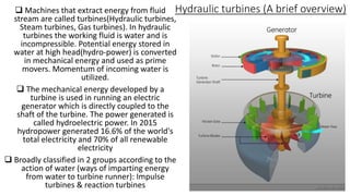
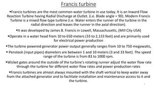
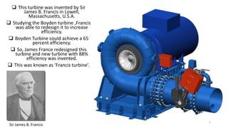
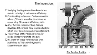
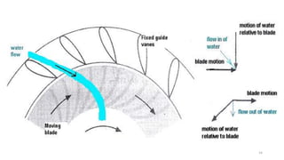
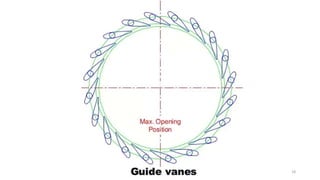

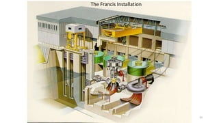
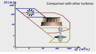


The document discusses the Francis turbine, which is the most commonly used water turbine today. It was invented in Lowell, Massachusetts by James Francis in 1849. He was able to redesign the existing Boyden turbine to significantly increase its efficiency from 65% to 88%. The key components of a Francis turbine include a scroll casing, guide vanes, runner, and draft tube. Water enters the scroll casing and is directed by the guide vanes to spin the radial vanes of the runner, which is connected to a shaft to power a generator. The draft tube recaptures pressure from the water exiting the runner. Francis turbines can operate over a wide range of heads from 10-650 meters and


