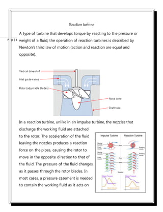
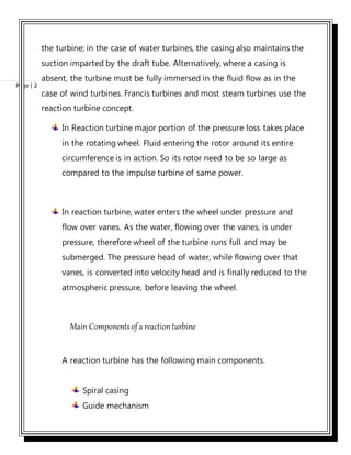
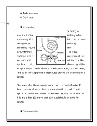
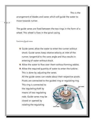
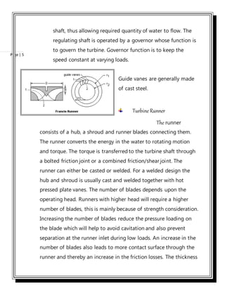
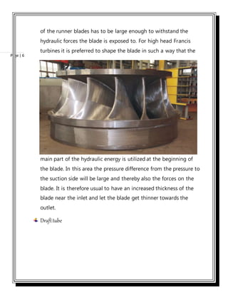
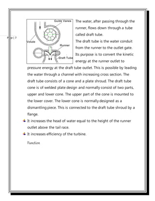
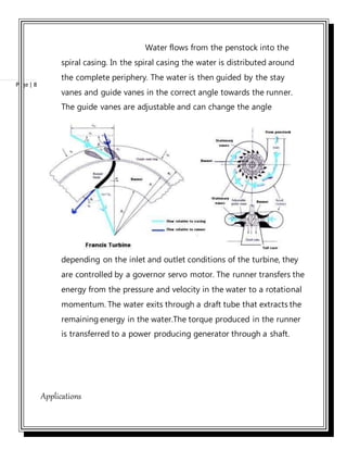
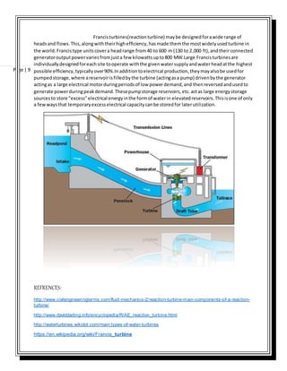
1. Fluid Mechanics 2 Assignment Reaction Turbine
REACTION TURBINE
Important Components and Working Functions.
MAY 16, 2016
CIVIL ENGINEERING DEPARTMENT
UCE&T, BZU, MUTAN
SUBMITTED TO
SUBMITTED BY
ROLL NO.
ASSIGNMENT NO.
SESSION
2. Page | 1
Reaction turbine
A type of turbine that develops torque by reacting to the pressure or
weight of a fluid; the operation of reaction turbines is described by
Newton's third law of motion (action and reaction are equal and
opposite).
In a reaction turbine, unlike in an impulse turbine, the nozzles that
discharge the working fluid are attached
to the rotor. The acceleration of the fluid
leaving the nozzles produces a reaction
force on the pipes, causing the rotor to
move in the opposite direction to that of
the fluid. The pressure of the fluid changes
as it passes through the rotor blades. In
most cases, a pressure casement is needed
to contain the working fluid as it acts on
3. Page | 2
the turbine; in the case of water turbines, the casing also maintains the
suction imparted by the draft tube. Alternatively, where a casing is
absent, the turbine must be fully immersed in the fluid flow as in the
case of wind turbines. Francis turbines and most steam turbines use the
reaction turbine concept.
In Reaction turbine major portion of the pressure loss takes place
in the rotating wheel. Fluid entering the rotor around its entire
circumference is in action. So its rotor need to be so large as
compared to the impulse turbine of same power.
In reaction turbine, water enters the wheel under pressure and
flow over vanes. As the water, flowing over the vanes, is under
pressure, therefore wheel of the turbine runs full and may be
submerged. The pressure head of water, while flowing over that
vanes, is converted into velocity head and is finally reduced to the
atmospheric pressure, before leaving the wheel.
Main Componentsofa reaction turbine
A reaction turbine has the following main components.
Spiral casing
Guide mechanism
4. Page | 3
Turbine runner
Draft tube
Spiralcasing
The casing of
reaction turbine is designed in
such a way that it’s cross sectional
area goes on reducing
uniformly around the
circumference. The cross
sectional area is maximum at the
entrance and minimum at the
tip. Due to this, the casing will be
of spiral shape. That is why it is called spiral casing or scroll casing.
The water from a pipeline is distributed around the guide ring in a
casing.
The material of the casing depends upon the head of water. If
head is up to 30 meter then concrete should be used. If head is
up to 100 meter then welded rolled steel plate should be used. If
it is more than 100 meter then cast steel should be used for
casing.
Guidemechanism
5. Page | 4
This is the
arrangement of blades and vanes which will guide the water to
move towards runner.
The guide vanes are fixed between the two rings in the form of a
wheel. This wheel is fixes in the spiral casing.
Functionsofguide vanes
Guide vanes allow the water to enter the runner without
shock. Guide vanes keep relative velocity at inlet of the
runner, tangential to the vane angle and thus results in
entering of water without shock.
Allow the water to flow over them without forming eddies.
Allow the required quantity of water to enter the turbine.
This is done by adjusting the vanes.
All the guide vanes can rotate about their respective pivots.
Pivots are connected to the guided ring or regulating ring.
This ring is connected to
the regulating shaft by
means of two regulating
rods. Guide vanes may be
closed or opened by
rotating the regulating
6. Page | 5
shaft, thus allowing required quantity of water to flow. The
regulating shaft is operated by a governor whose function is
to govern the turbine. Governor function is to keep the
speed constant at varying loads.
Guide vanes are generally made
of cast steel.
Turbine Runner
The runner
consists of a hub, a shroud and runner blades connecting them.
The runner converts the energy in the water to rotating motion
and torque. The torque is transferred to the turbine shaft through
a bolted friction joint or a combined friction/shear joint. The
runner can either be casted or welded. For a welded design the
hub and shroud is usually cast and welded together with hot
pressed plate vanes. The number of blades depends upon the
operating head. Runners with higher head will require a higher
number of blades, this is mainly because of strength consideration.
Increasing the number of blades reduce the pressure loading on
the blade which will help to avoid cavitation and also prevent
separation at the runner inlet during low loads. An increase in the
number of blades also leads to more contact surface through the
runner and thereby an increase in the friction losses. The thickness
7. Page | 6
of the runner blades has to be large enough to withstand the
hydraulic forces the blade is exposed to. For high head Francis
turbines it is preferred to shape the blade in such a way that the
main part of the hydraulic energy is utilized at the beginning of
the blade. In this area the pressure difference from the pressure to
the suction side will be large and thereby also the forces on the
blade. It is therefore usual to have an increased thickness of the
blade near the inlet and let the blade get thinner towards the
outlet.
Drafttube
8. Page | 7
The water, after passing through the
runner, flows down through a tube
called draft tube.
The draft tube is the water conduit
from the runner to the outlet gate.
Its purpose is to convert the kinetic
energy at the runner outlet to
pressure energy at the draft tube outlet. This is possible by leading
the water through a channel with increasing cross section. The
draft tube consists of a cone and a plate shroud. The draft tube
cone is of welded plate design and normally consist of two parts,
upper and lower cone. The upper part of the cone is mounted to
the lower cover. The lower cone is normally designed as a
dismantling piece. This is connected to the draft tube shroud by a
flange.
It increases the head of water equal to the height of the runner
outlet above the tail race.
It increases efficiency of the turbine.
Function
9. Page | 8
Water flows from the penstock into the
spiral casing. In the spiral casing the water is distributed around
the complete periphery. The water is then guided by the stay
vanes and guide vanes in the correct angle towards the runner.
The guide vanes are adjustable and can change the angle
depending on the inlet and outlet conditions of the turbine, they
are controlled by a governor servo motor. The runner transfers the
energy from the pressure and velocity in the water to a rotational
momentum. The water exits through a draft tube that extracts the
remaining energy in the water.The torque produced in the runner
is transferred to a power producing generator through a shaft.
Applications
10. Page | 9
Francisturbines(reactionturbine) maybe designedforawide range of
headsand flows.This,alongwiththeirhighefficiency,hasmade themthe mostwidelyusedturbine in
the world.Francistype unitscovera headrange from40 to 600 m (130 to 2,000 ft),andtheirconnected
generatoroutputpowervariesfromjusta few kilowattsupto800 MW.Large Francisturbinesare
individuallydesignedforeachsite tooperate withthe givenwatersupplyandwaterheadatthe highest
possible efficiency,typicallyover90%.Inadditiontoelectrical production,theymayalsobe usedfor
pumpedstorage,where areservoirisfilledbythe turbine (actingasa pump) drivenbythe generator
actingas a large electrical motorduringperiodsof low powerdemand,and thenreversedandusedto
generate powerduringpeakdemand.Thesepumpstorage reservoirs,etc.actas large energystorage
sourcesto store "excess"electrical energyinthe formof waterin elevatedreservoirs.Thisisone of only
a fewwaysthat temporaryexcesselectrical capacitycanbe storedfor laterutilization.
REFRENCES:
http://www.civilengineeringterms.com/fluid-mechanics-2/reaction-turbine-main-components-of-a-reaction-
turbine/
http://www.daviddarling.info/encyclopedia/R/AE_reaction_turbine.html
http://waterturbines.wikidot.com/main:types-of-water-turbines
https://en.wikipedia.org/wiki/Francis_turbine