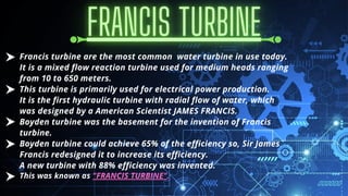
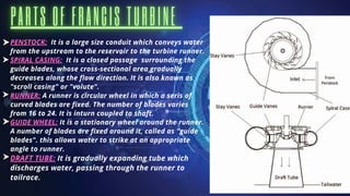
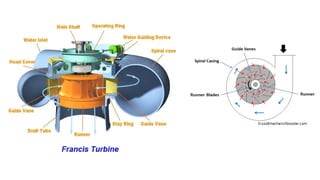
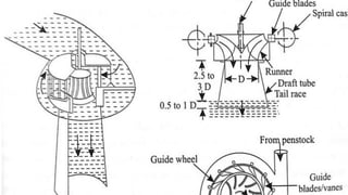
Presented by Nischitha.D.N
INTRODUCTION
INTRODUCTION
INTRODUCTION
A turbine is a rotary machanical device that converts
kinetic energy of a fluid into mechanical work by the
rotation of shaft.
Hydraulic turbine converts the potential and kinetic
energy of water into mechanical work (power). It is
classified into two types i.e., impulse and reaction
turbine.
Francis turbine is one of the examples of the
hydraulic reaction turbine
Francis turbine are the most common water turbine in use today.
It is a mixed flow reaction turbine used for medium heads ranging
from 10 to 650 meters.
This turbine is primarily used for electrical power production.
It is the first hydraulic turbine with radial flow of water, which
was designed by a American Scientist JAMES FRANCIS.
Boyden turbine was the basement for the invention of Francis
turbine.
Boyden turbine could achieve 65% of the efficiency so, Sir James
Francis redesigned it to increase its efficiency.
A new turbine with 88% efficiency was invented.
This was known as "FRANCIS TURBINE".
PENSTOCK: It is a large size conduit which conveys water
from the upstream to the reservoir to the turbine runner.
SPIRAL CASING: It is a closed passage surrounding the
guide blades, whose cross-sectional area gradually
decreases along the flow direction. It is also known as
"scroll casing" or "volute".
RUNNER: A runner is circular wheel in which a seris of
curved blades are fixed. The number of blades varies
from 16 to 24. It is inturn coupled to shaft.
GUIDE WHEEL: It is a stationary wheel around the runner.
A number of blades are fixed around it, called as "guide
blades". this allows water to strike at an appropriate
angle to runner.
DRAFT TUBE: It is gradually expanding tube which
discharges water, passing through the runner to
tailrace.
The water from the reservoir is carried to the turbine through penstock
and enters the spiral casing.
The casing distributes water evenly aound the circumference of the
turbine runner.
From the spiral casing, water passes through stay vane and it directs
water to the guide vanes.
These guide vanes regulatethe quantity of water supplied to the
runner.
The water enters the runner with a low velocity and considerable
pressure.
As the water flows through the runner, the direction of flow of
water is changed from radial to axial and produce a
circumferential force on the runner.
This circumferential force makes the runner to rotate and thus
the useful output work is obtained
.
The runner is keyed the shaft which is further coupled to the
electric generator.
The water after passing through the runner flows to the tail
race through a draft tube.
It is a most widely used turbine (about 70 - 80%).
Effective use of water pressure as well as velocity.
It is American standard turbine.
Has a very good efficiency (80 - 90%).
Most expensive (high cost).
Due to complex design amd large number of moving parts,
maintenance and repair is difficult and costly.
It is applicable to flow of medium head only.
CONCLUSION
New types of design are developed to reduce cost and
complexity of mechanics.
Modified turbine include INLINE LINKLESS FRANCIS
TURBINE, CROSS- FLOW TURBINE, etc.
These new turbinerequire less space, simplified
designs, less moving parts, etc.
4PS21CS061.pdf

4PS21CS061.pdf

  • 1.
  • 3.
    INTRODUCTION INTRODUCTION INTRODUCTION A turbine isa rotary machanical device that converts kinetic energy of a fluid into mechanical work by the rotation of shaft. Hydraulic turbine converts the potential and kinetic energy of water into mechanical work (power). It is classified into two types i.e., impulse and reaction turbine. Francis turbine is one of the examples of the hydraulic reaction turbine
  • 4.
    Francis turbine arethe most common water turbine in use today. It is a mixed flow reaction turbine used for medium heads ranging from 10 to 650 meters. This turbine is primarily used for electrical power production. It is the first hydraulic turbine with radial flow of water, which was designed by a American Scientist JAMES FRANCIS. Boyden turbine was the basement for the invention of Francis turbine. Boyden turbine could achieve 65% of the efficiency so, Sir James Francis redesigned it to increase its efficiency. A new turbine with 88% efficiency was invented. This was known as "FRANCIS TURBINE".
  • 5.
    PENSTOCK: It isa large size conduit which conveys water from the upstream to the reservoir to the turbine runner. SPIRAL CASING: It is a closed passage surrounding the guide blades, whose cross-sectional area gradually decreases along the flow direction. It is also known as "scroll casing" or "volute". RUNNER: A runner is circular wheel in which a seris of curved blades are fixed. The number of blades varies from 16 to 24. It is inturn coupled to shaft. GUIDE WHEEL: It is a stationary wheel around the runner. A number of blades are fixed around it, called as "guide blades". this allows water to strike at an appropriate angle to runner. DRAFT TUBE: It is gradually expanding tube which discharges water, passing through the runner to tailrace.
  • 6.
    The water fromthe reservoir is carried to the turbine through penstock and enters the spiral casing. The casing distributes water evenly aound the circumference of the turbine runner. From the spiral casing, water passes through stay vane and it directs water to the guide vanes. These guide vanes regulatethe quantity of water supplied to the runner. The water enters the runner with a low velocity and considerable pressure.
  • 7.
    As the waterflows through the runner, the direction of flow of water is changed from radial to axial and produce a circumferential force on the runner. This circumferential force makes the runner to rotate and thus the useful output work is obtained . The runner is keyed the shaft which is further coupled to the electric generator. The water after passing through the runner flows to the tail race through a draft tube.
  • 10.
    It is amost widely used turbine (about 70 - 80%). Effective use of water pressure as well as velocity. It is American standard turbine. Has a very good efficiency (80 - 90%).
  • 11.
    Most expensive (highcost). Due to complex design amd large number of moving parts, maintenance and repair is difficult and costly. It is applicable to flow of medium head only.
  • 12.
    CONCLUSION New types ofdesign are developed to reduce cost and complexity of mechanics. Modified turbine include INLINE LINKLESS FRANCIS TURBINE, CROSS- FLOW TURBINE, etc. These new turbinerequire less space, simplified designs, less moving parts, etc.