Download as PDF, PPTX
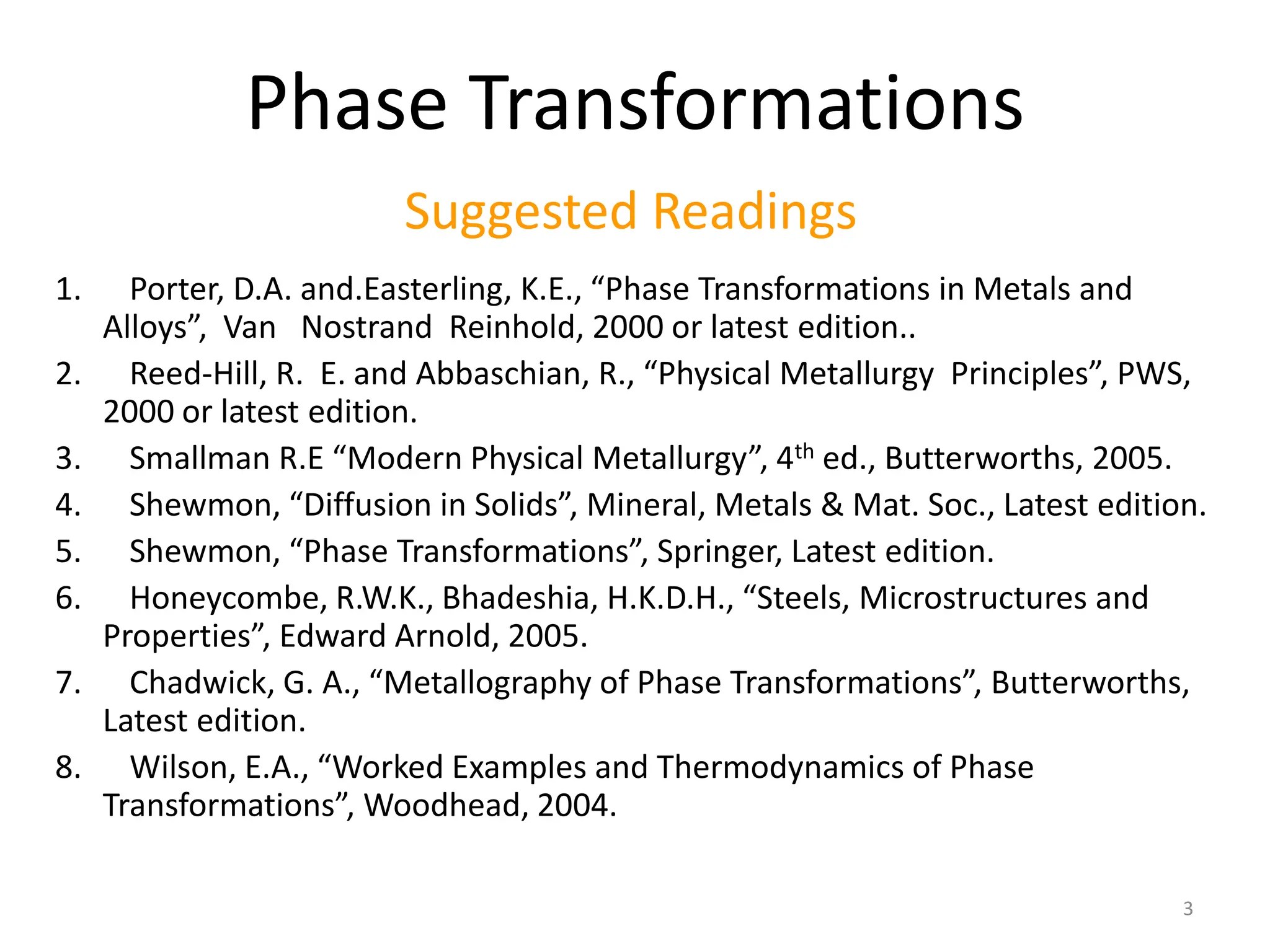
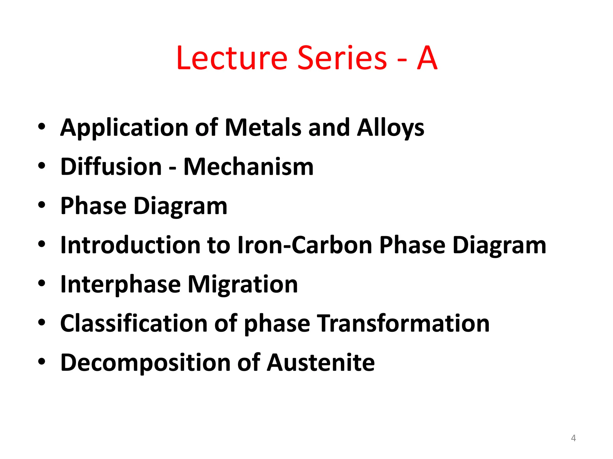
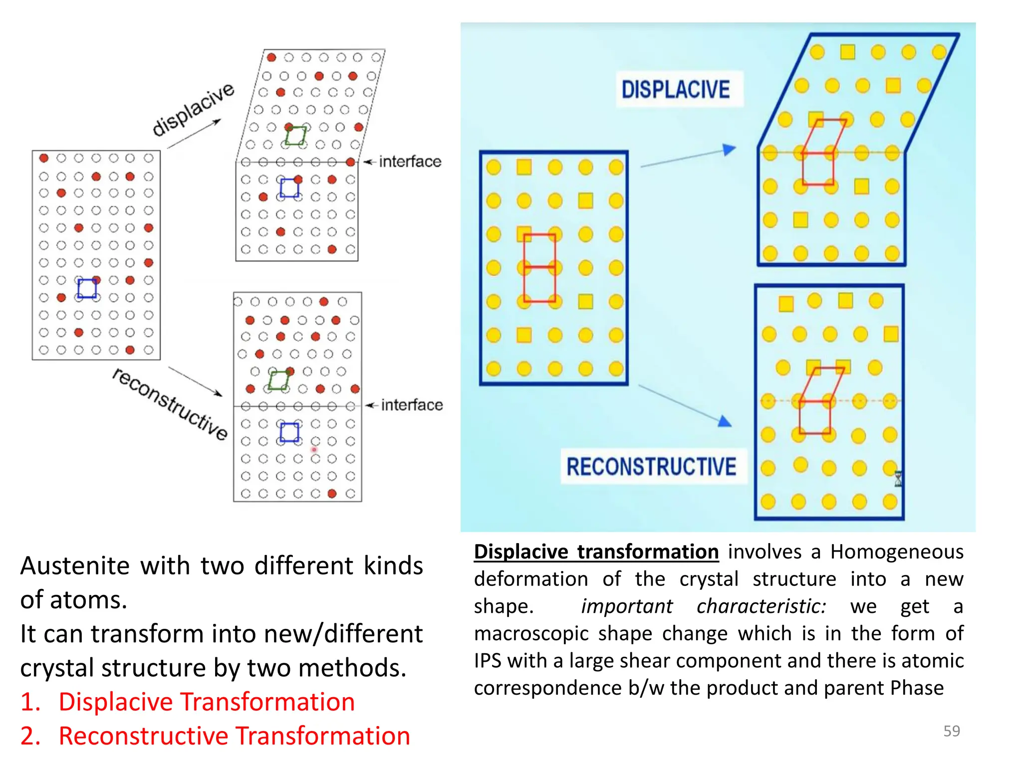
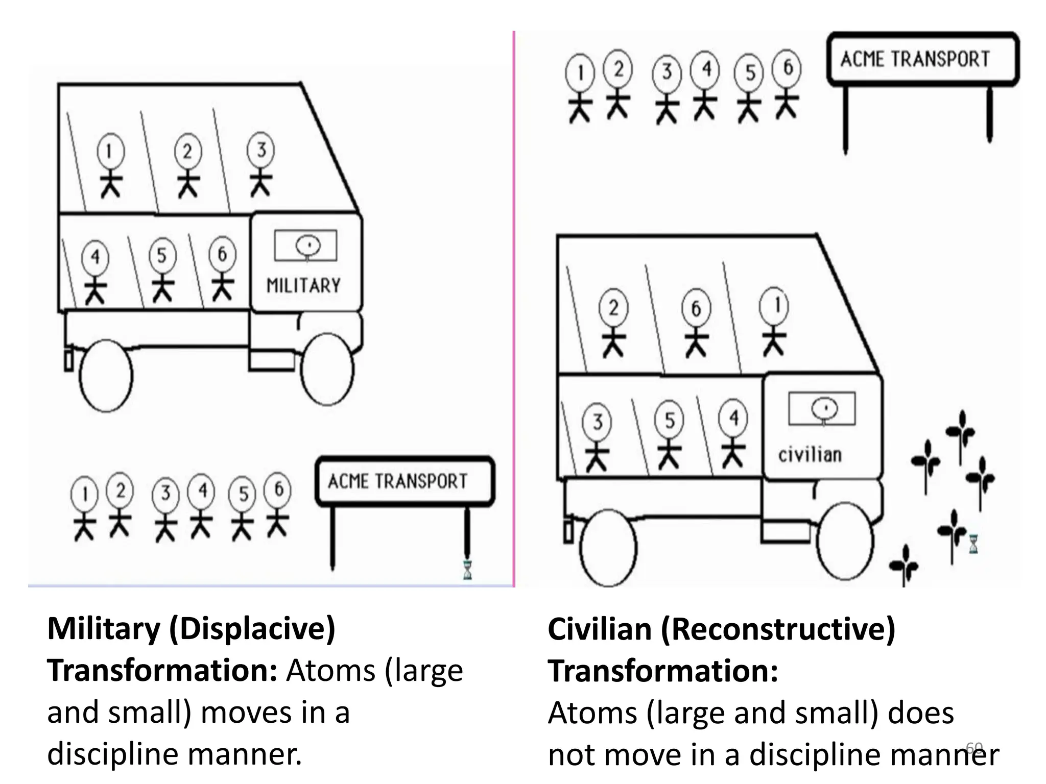
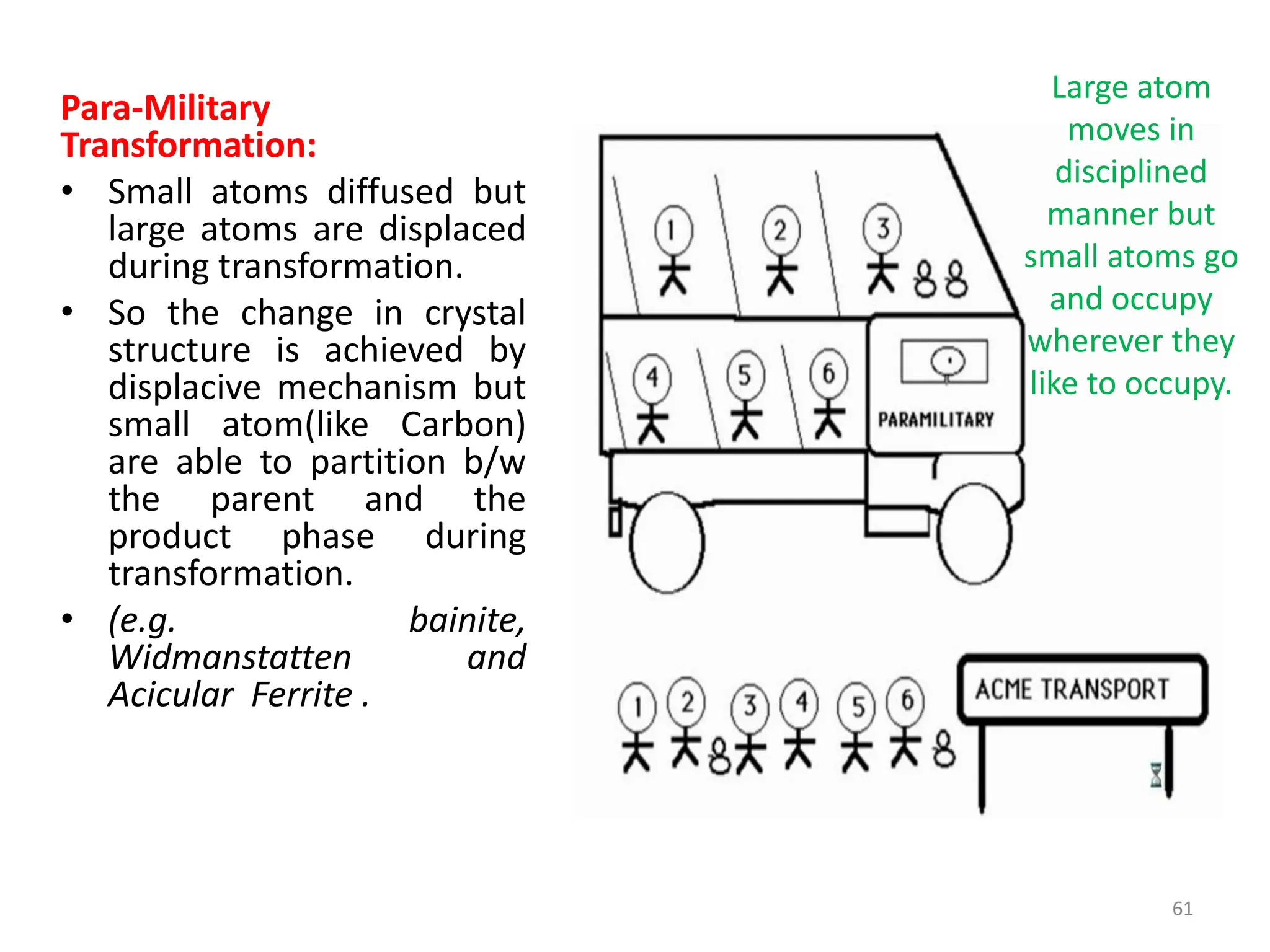
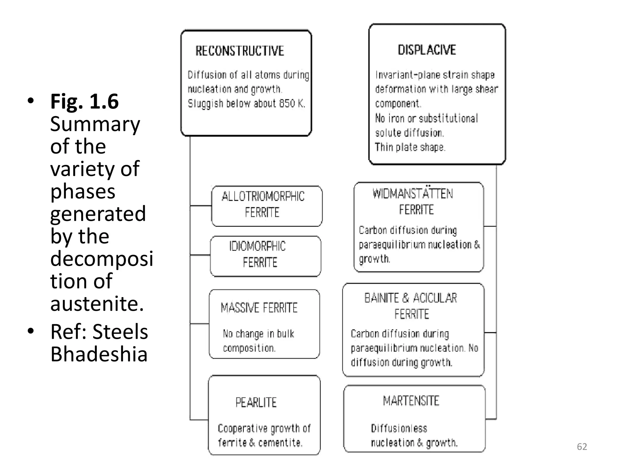

The document discusses phase transformations in solid metals and alloys. It provides contact information for Dr. Muhammad Ali Siddiqui of NED University of Pakistan who teaches a course on this topic. It then lists several recommended textbooks on phase transformations and diagrams before outlining the topics that will be covered in the lecture series, including diffusion mechanisms, phase diagrams, and the classification of phase transformations.


