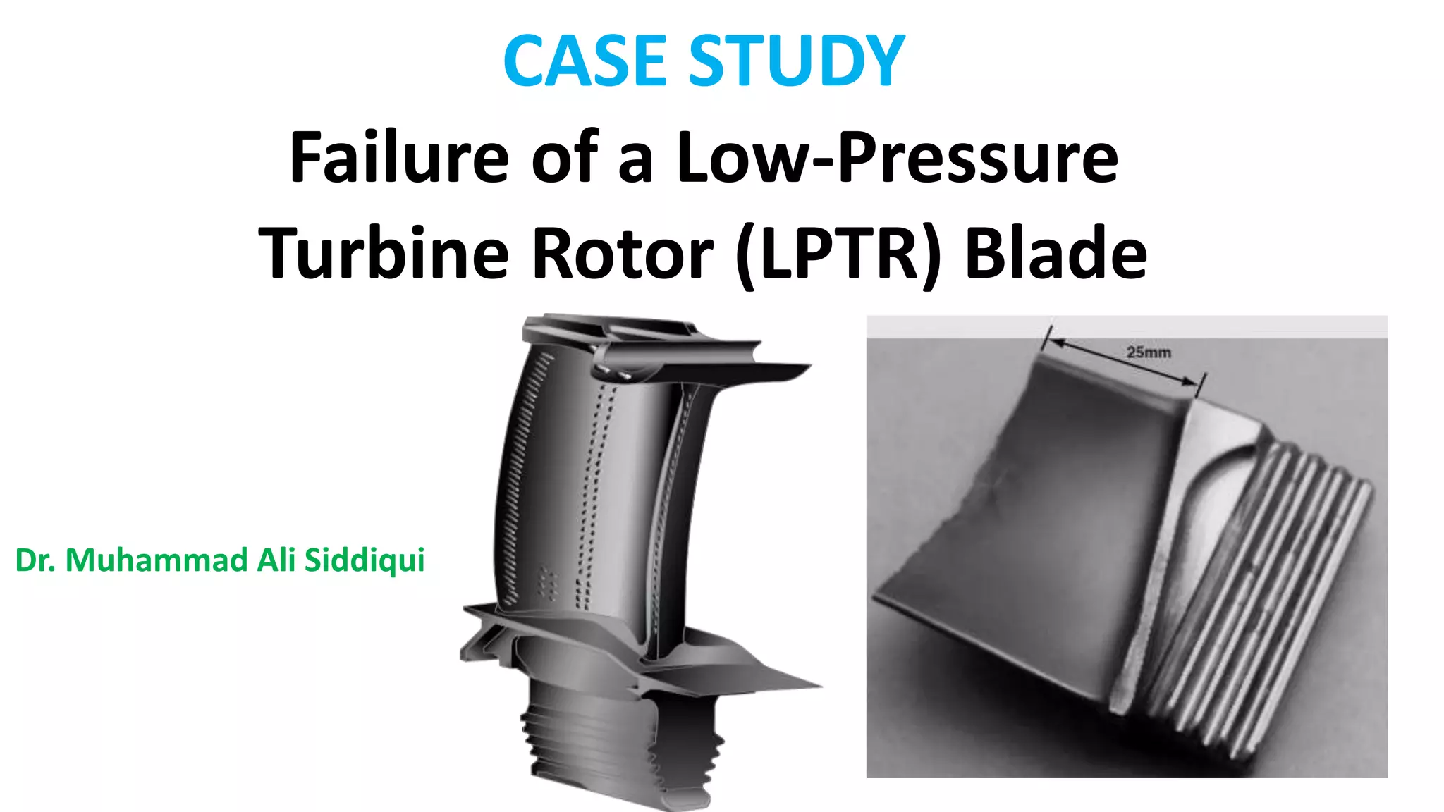
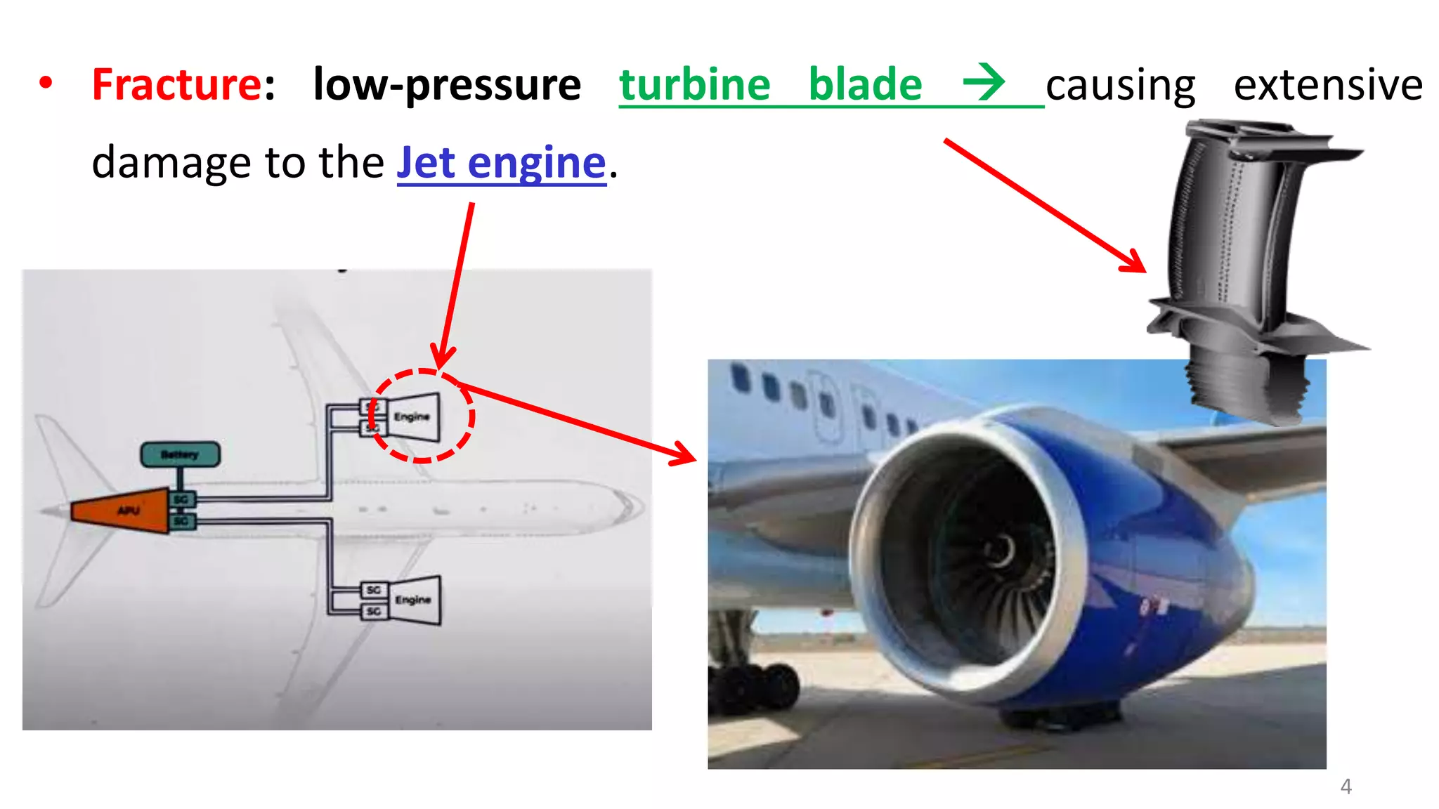
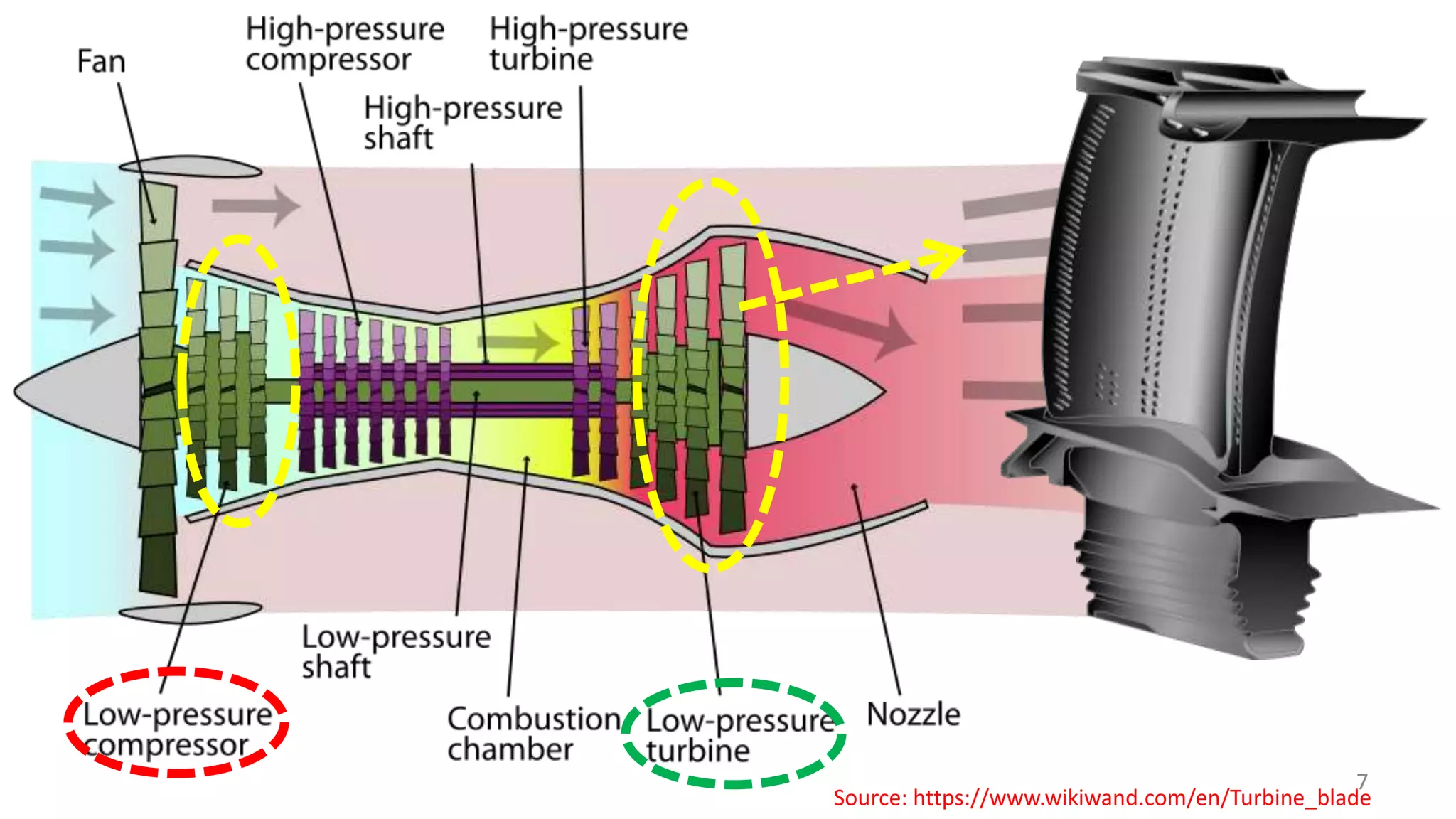
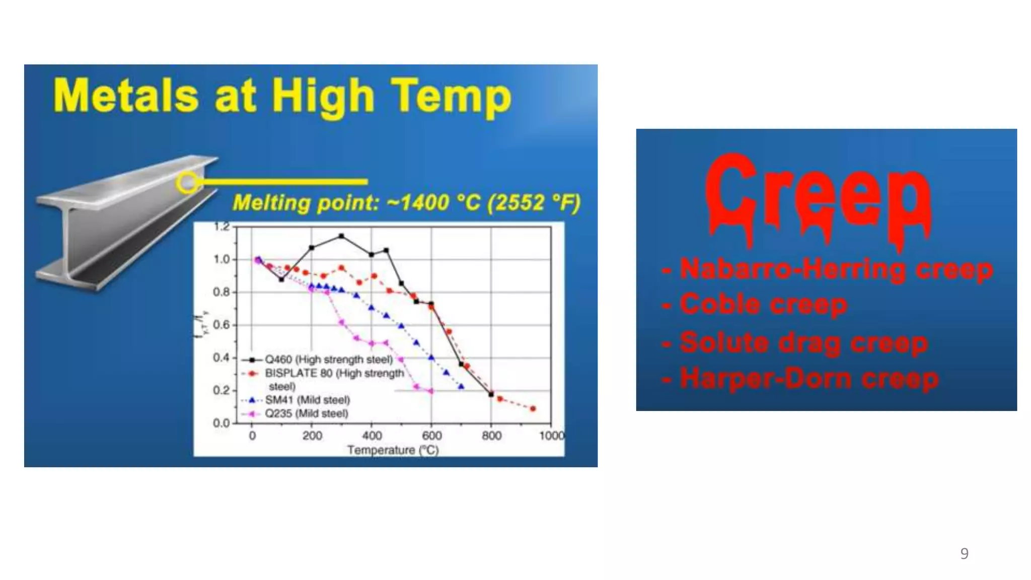
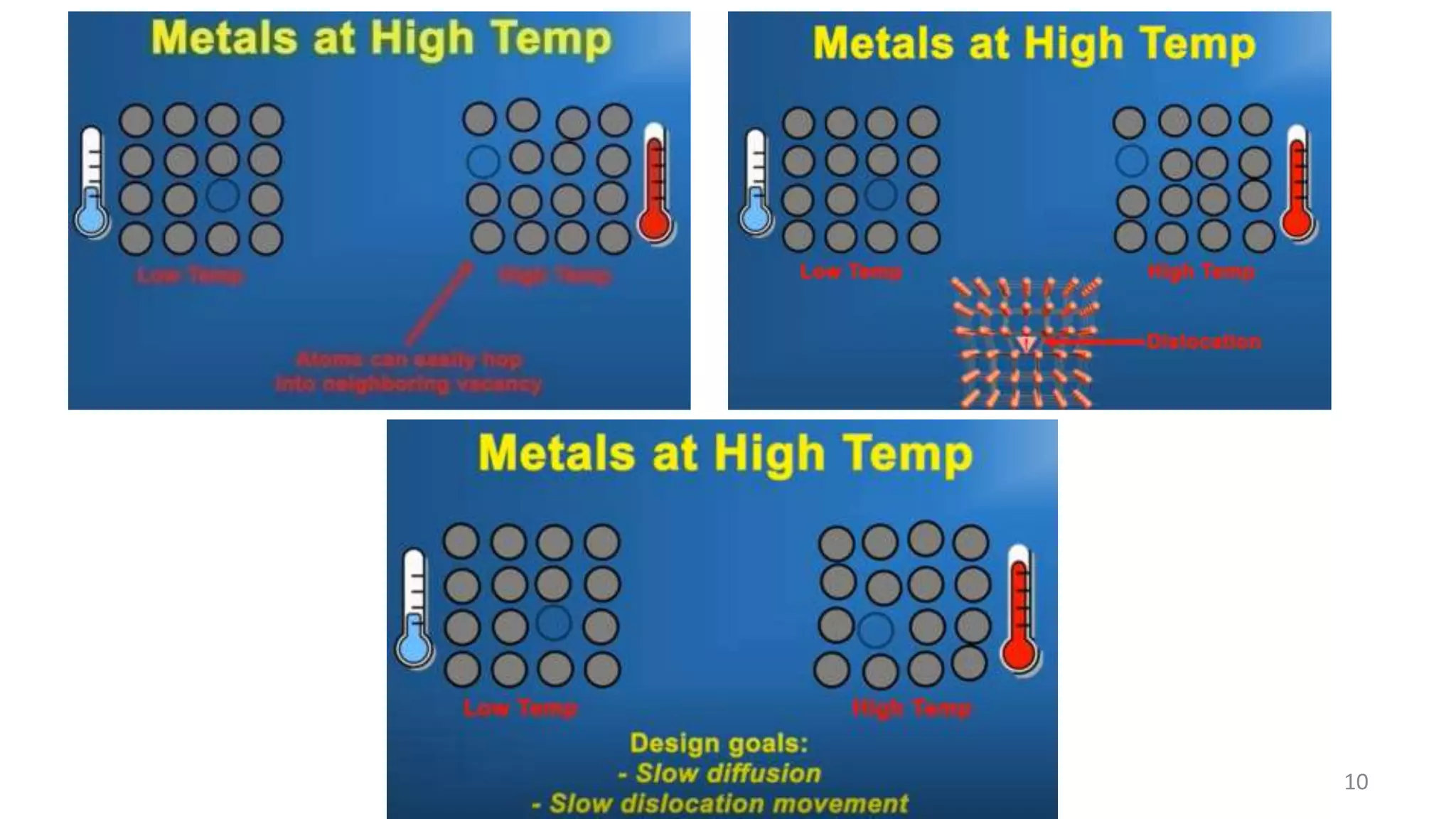
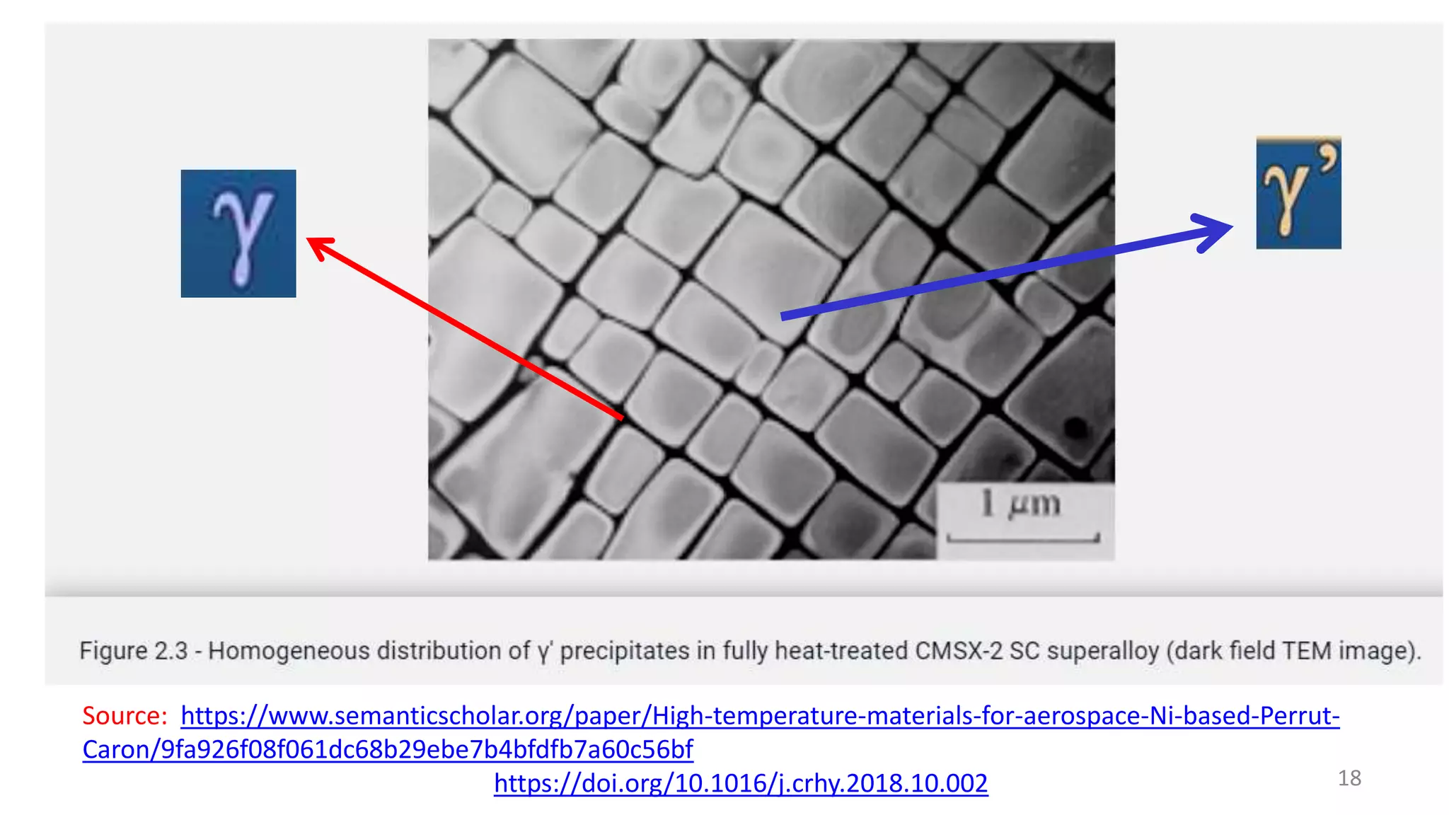
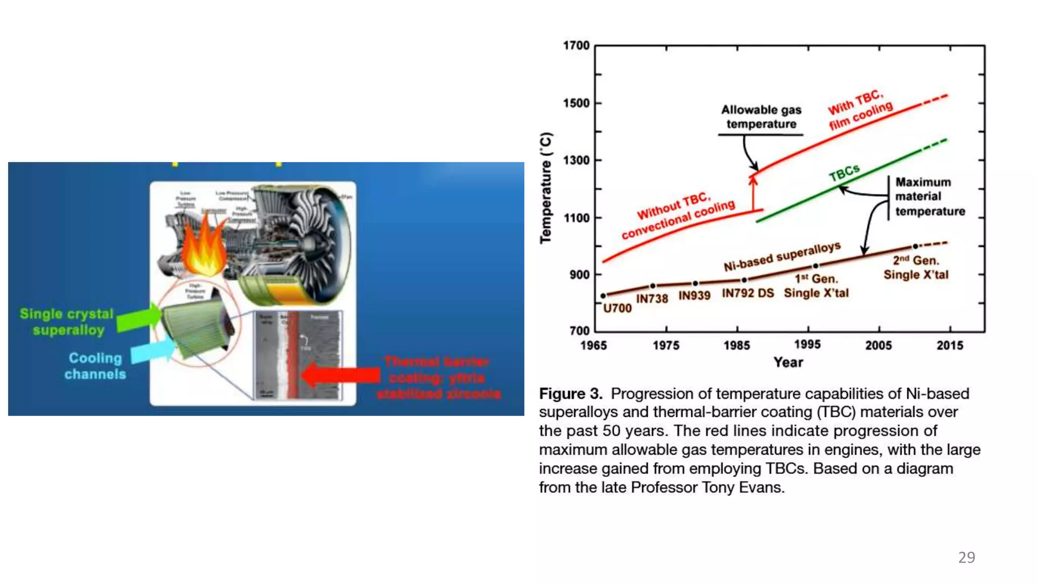
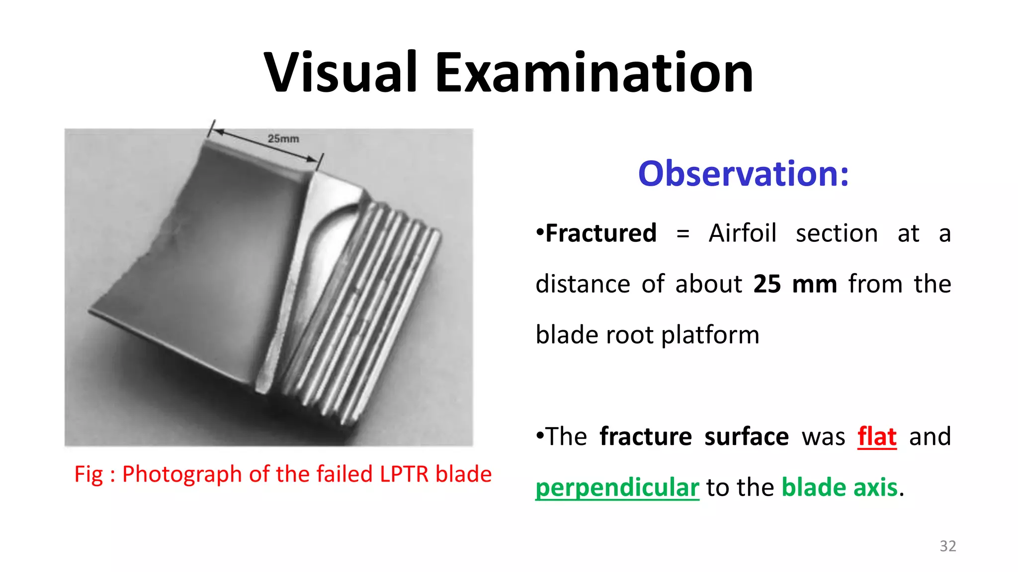
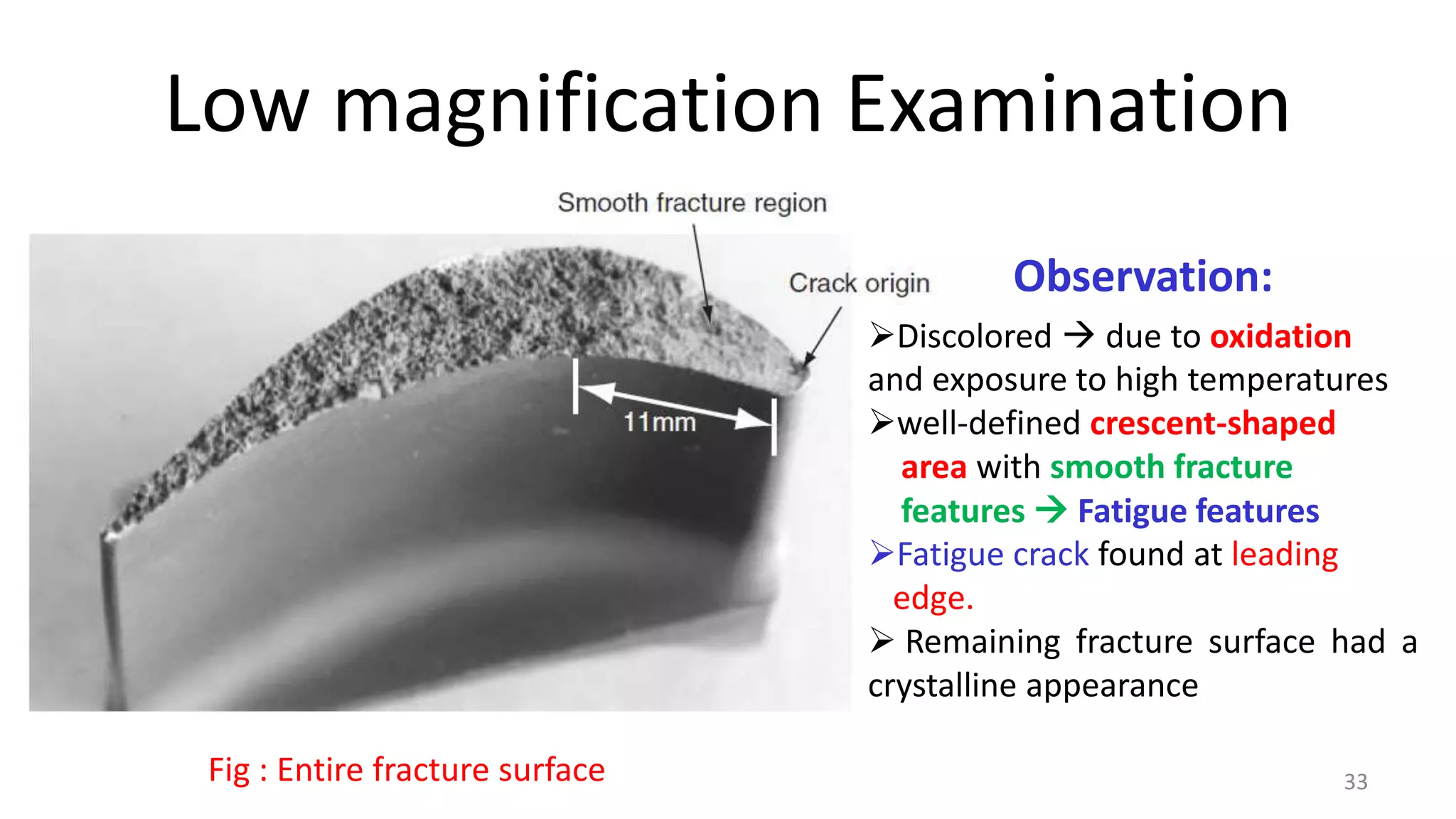
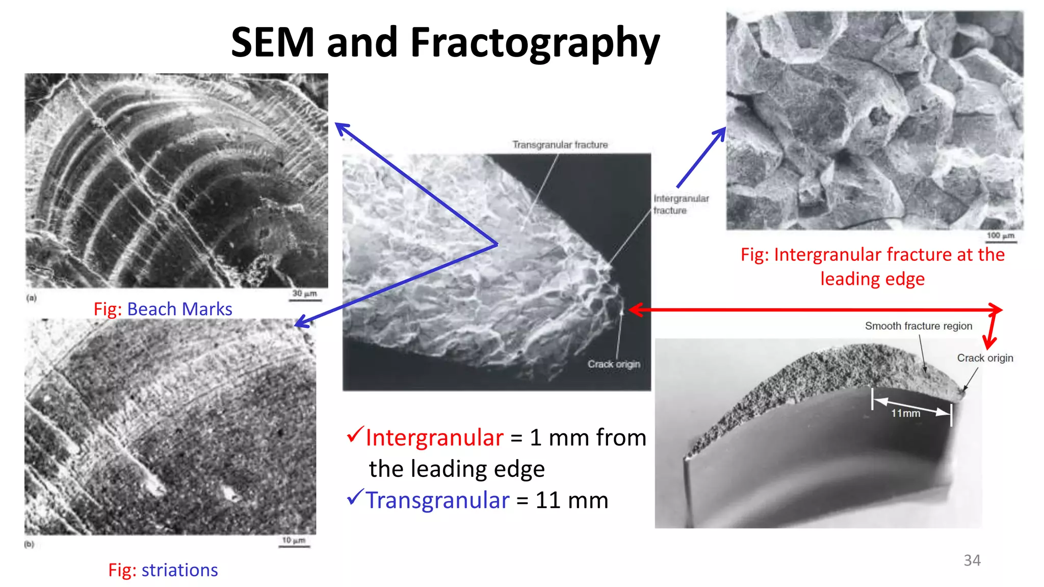
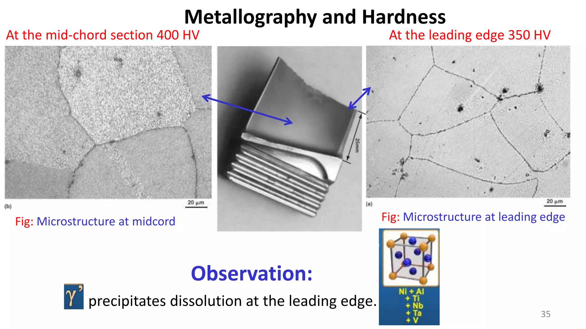
CASE STUDY
Failure of a Low-Pressure
Turbine Rotor (LPTR) Blade
Dr. Muhammad Ali Siddiqui
Content
 Background with literature review about super alloys,
properties, alloy design and manufacturing process
 Testing Procedure and Results
Visual Examination of General Physical Features
Scanning Electron Microscopy and Fractography
Metallography and Hardness
 Discussion
 Conclusion
2
Background and Literature Review
3
• Fracture: low-pressure turbine blade  causing extensive
damage to the Jet engine.
4
5
6
7
Source: https://www.wikiwand.com/en/Turbine_blade
8
9
10
11
12
13
Ni
14
Ni
Al
Ni Al
Thermodynamic favour ordered structure
15
16
70% of intermetallic make it suitable for
applications
Other Alloying
17
18
Source: https://www.semanticscholar.org/paper/High-temperature-materials-for-aerospace-Ni-based-Perrut-
Caron/9fa926f08f061dc68b29ebe7b4bfdfb7a60c56bf
https://doi.org/10.1016/j.crhy.2018.10.002
19
20
21
22
Investment (lost wax) casting
Materials 2019, 12(11), 1781; https://doi.org/10.3390/ma12111781
23
24
26
ceramic topcoat is
deposited by electron beam
physical vapor deposition
(EBPVD) or air plasma-
spraying (APS)
Sandwiched between the
topcoat and the metallic
bond coat is the thermally
grown oxide (TGO)
Surface treated: THERMAL-BARRIER COATINGS (TBCs)
Examples: Aluminide coatings
27
First stage (the stage directly following the combustor) of a modern gas turbine
faces temperatures around 1,370 °C
Modern military jet engines, like the Snecma M88, can see turbine temperatures
of 1,590 °C.
Cross sectional view
28
29
Case Study
30
 LPTR blade failed
 Ni-base superalloys
 causing extensive damage to the engine.
31
Background
Visual Examination
32
Observation:
•Fractured = Airfoil section at a
distance of about 25 mm from the
blade root platform
•The fracture surface was flat and
perpendicular to the blade axis.
Fig : Photograph of the failed LPTR blade
Low magnification Examination
33
Fig : Entire fracture surface
Observation:
Discolored  due to oxidation
and exposure to high temperatures
well-defined crescent-shaped
area with smooth fracture
features  Fatigue features
Fatigue crack found at leading
edge.
 Remaining fracture surface had a
crystalline appearance
34
Intergranular = 1 mm from
the leading edge
Transgranular = 11 mm
SEM and Fractography
Fig: Intergranular fracture at the
leading edge
Fig: Beach Marks
Fig: striations
35
Metallography and Hardness
Fig: Microstructure at leading edge
Fig: Microstructure at midcord
Observation:
precipitates dissolution at the leading edge.
At the leading edge 350 HV
At the mid-chord section 400 HV
Discussion
1. Failure Mechanism:
• Intergranular mode (IM) to about 1 mm from the leading edge
• Followed by a transgranular mode (TM) of about 11 mm
– IM Principal mode in high-temperature creep/stress rupture.
– Cracking occur principally along the grain boundaries normal to the
major stress axis of the blade.
– TM The incremental crack growth is evidenced by the presence
of closely spaced striations.
36
• Therefore, it appears that the crack initiated at the leading edge
of the blade by stress rupture and propagated fast to a distance of
about 1 mm.
• In the second stage, this crack acted as a notch for stress
concentration and led to the propagation of the crack by fatigue.
• The fatigue crack then propagated progressively up to about 11
mm from the leading edge before giving way to overload fracture.
37
Cont…
2. Cause of Failure:
• Dissolution of gamma prime (γ-prime)
precipitates at the leading edge clearly indicates
that the blade was exposed to high temperatures
 the hardness  the creep resistance of
the blade drastically.
38
Conclusion
• The cracking of the blade took place by stress rupture.
• Once the initial crack had formed due to stress rupture, the crack further
propagated under the cyclic loading experienced by the blade during
service.
• The factors responsible for such cracking are high operating temperatures
and stresses that causes the dissolution of the precipitates.
39
Thank You
40

Case study: Failure Analysis of LPTR blade

  • 1.
    CASE STUDY Failure ofa Low-Pressure Turbine Rotor (LPTR) Blade Dr. Muhammad Ali Siddiqui
  • 2.
    Content  Background withliterature review about super alloys, properties, alloy design and manufacturing process  Testing Procedure and Results Visual Examination of General Physical Features Scanning Electron Microscopy and Fractography Metallography and Hardness  Discussion  Conclusion 2
  • 3.
  • 4.
    • Fracture: low-pressureturbine blade  causing extensive damage to the Jet engine. 4
  • 5.
  • 6.
  • 7.
  • 8.
  • 9.
  • 10.
  • 11.
  • 12.
  • 13.
  • 14.
  • 15.
  • 16.
    16 70% of intermetallicmake it suitable for applications
  • 17.
  • 18.
  • 19.
  • 20.
  • 21.
  • 22.
    22 Investment (lost wax)casting Materials 2019, 12(11), 1781; https://doi.org/10.3390/ma12111781
  • 23.
  • 24.
  • 25.
    26 ceramic topcoat is depositedby electron beam physical vapor deposition (EBPVD) or air plasma- spraying (APS) Sandwiched between the topcoat and the metallic bond coat is the thermally grown oxide (TGO) Surface treated: THERMAL-BARRIER COATINGS (TBCs) Examples: Aluminide coatings
  • 26.
    27 First stage (thestage directly following the combustor) of a modern gas turbine faces temperatures around 1,370 °C Modern military jet engines, like the Snecma M88, can see turbine temperatures of 1,590 °C. Cross sectional view
  • 27.
  • 28.
  • 29.
  • 30.
     LPTR bladefailed  Ni-base superalloys  causing extensive damage to the engine. 31 Background
  • 31.
    Visual Examination 32 Observation: •Fractured =Airfoil section at a distance of about 25 mm from the blade root platform •The fracture surface was flat and perpendicular to the blade axis. Fig : Photograph of the failed LPTR blade
  • 32.
    Low magnification Examination 33 Fig: Entire fracture surface Observation: Discolored  due to oxidation and exposure to high temperatures well-defined crescent-shaped area with smooth fracture features  Fatigue features Fatigue crack found at leading edge.  Remaining fracture surface had a crystalline appearance
  • 33.
    34 Intergranular = 1mm from the leading edge Transgranular = 11 mm SEM and Fractography Fig: Intergranular fracture at the leading edge Fig: Beach Marks Fig: striations
  • 34.
    35 Metallography and Hardness Fig:Microstructure at leading edge Fig: Microstructure at midcord Observation: precipitates dissolution at the leading edge. At the leading edge 350 HV At the mid-chord section 400 HV
  • 35.
    Discussion 1. Failure Mechanism: •Intergranular mode (IM) to about 1 mm from the leading edge • Followed by a transgranular mode (TM) of about 11 mm – IM Principal mode in high-temperature creep/stress rupture. – Cracking occur principally along the grain boundaries normal to the major stress axis of the blade. – TM The incremental crack growth is evidenced by the presence of closely spaced striations. 36
  • 36.
    • Therefore, itappears that the crack initiated at the leading edge of the blade by stress rupture and propagated fast to a distance of about 1 mm. • In the second stage, this crack acted as a notch for stress concentration and led to the propagation of the crack by fatigue. • The fatigue crack then propagated progressively up to about 11 mm from the leading edge before giving way to overload fracture. 37 Cont…
  • 37.
    2. Cause ofFailure: • Dissolution of gamma prime (γ-prime) precipitates at the leading edge clearly indicates that the blade was exposed to high temperatures  the hardness  the creep resistance of the blade drastically. 38
  • 38.
    Conclusion • The crackingof the blade took place by stress rupture. • Once the initial crack had formed due to stress rupture, the crack further propagated under the cyclic loading experienced by the blade during service. • The factors responsible for such cracking are high operating temperatures and stresses that causes the dissolution of the precipitates. 39
  • 39.