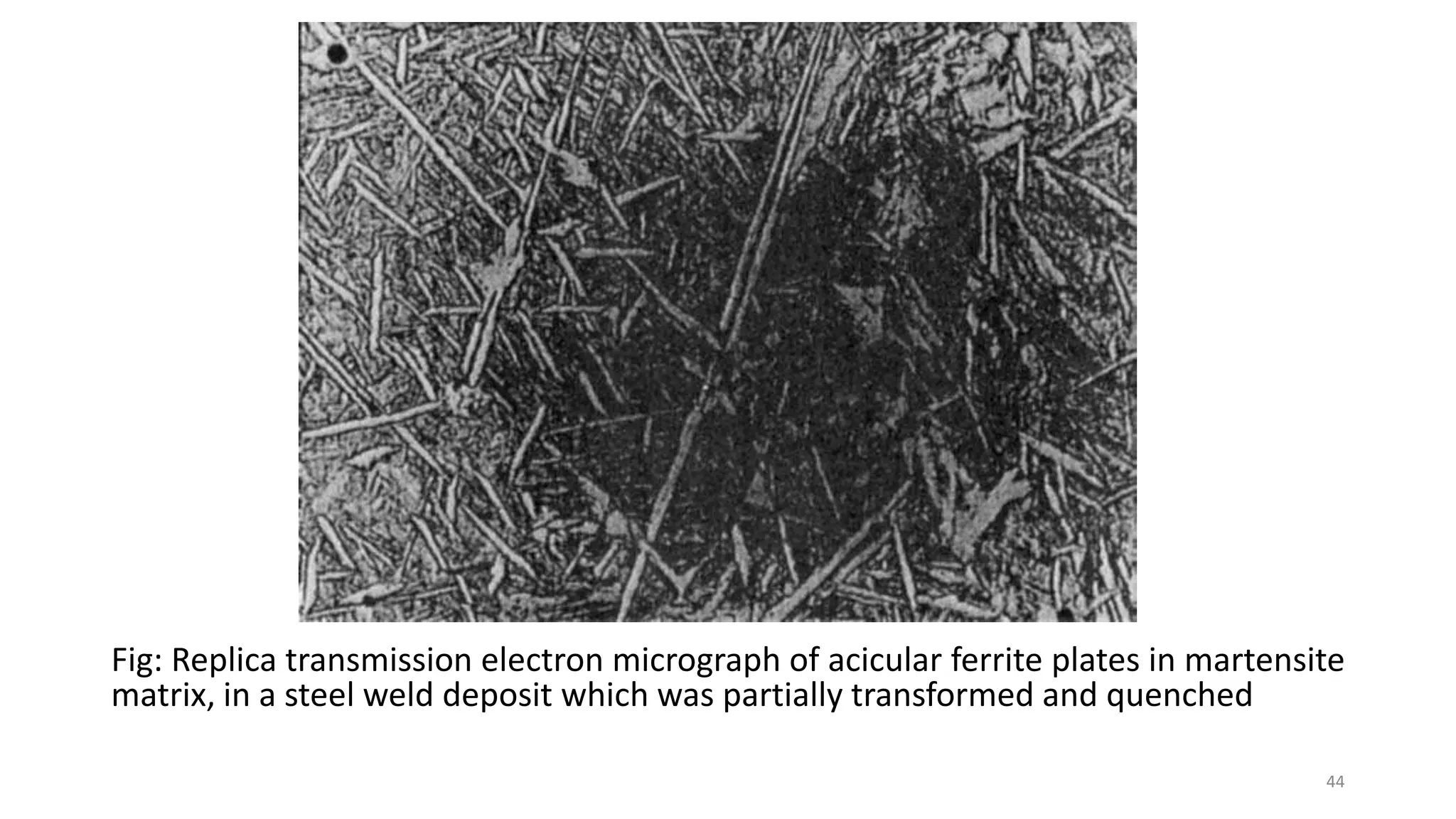
Download as PDF, PPTX

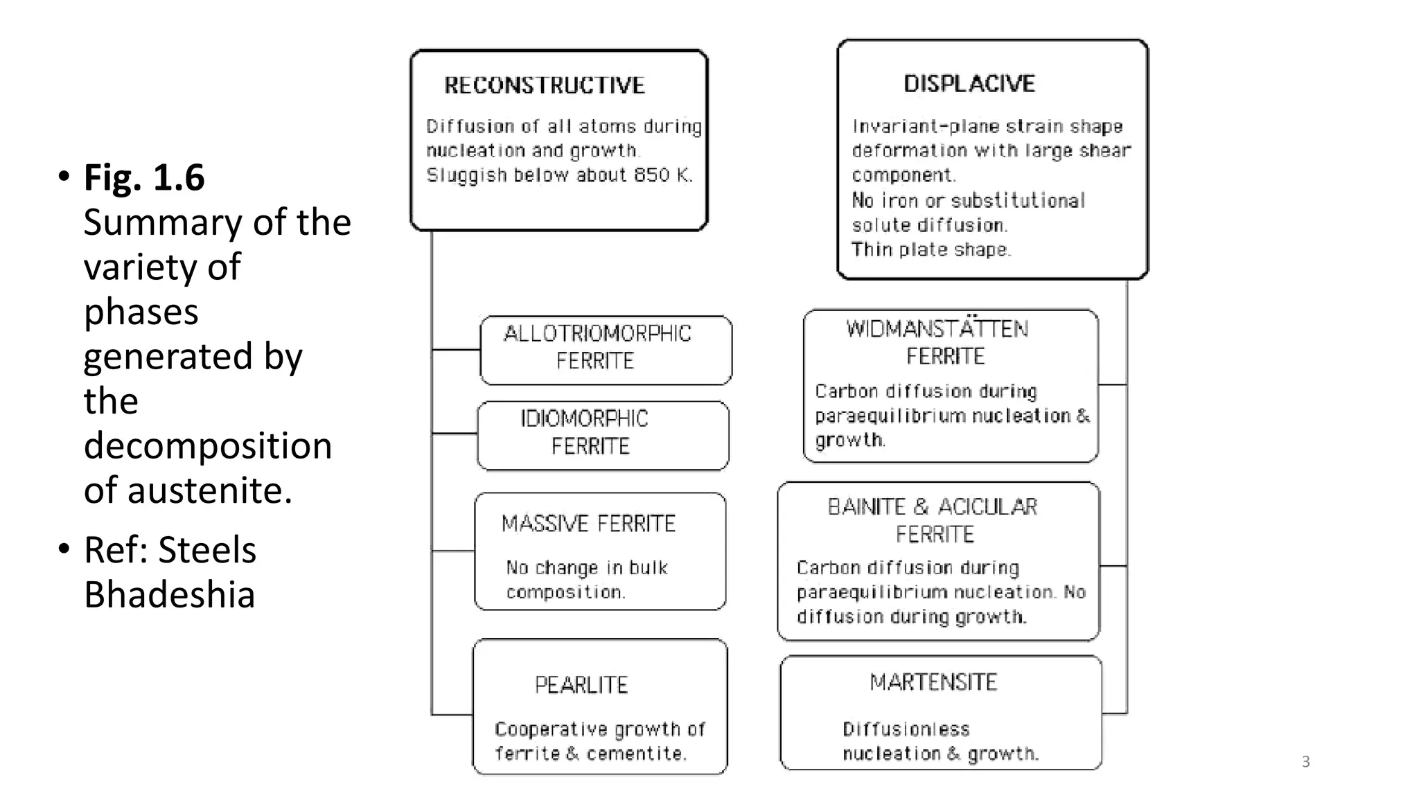

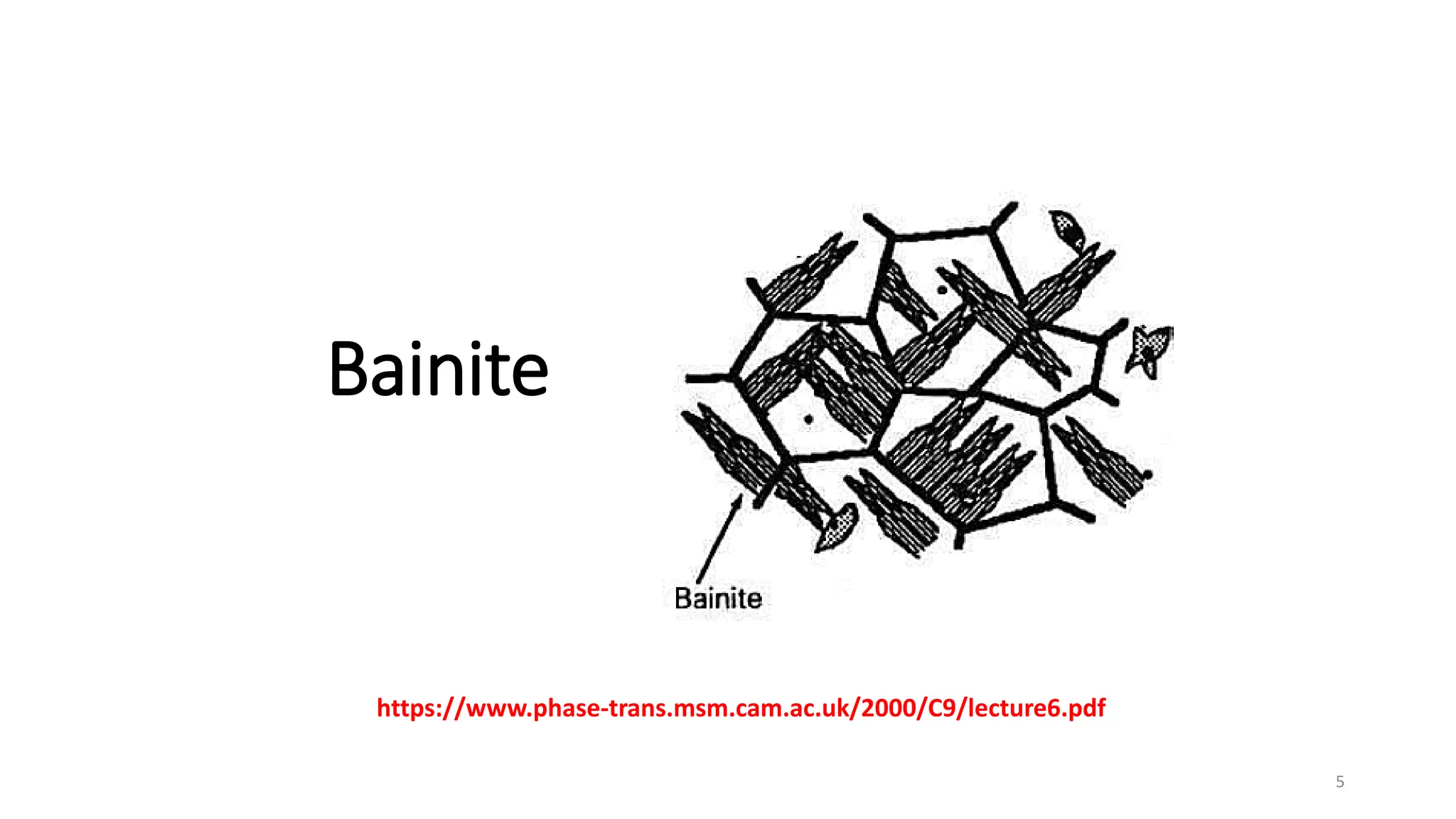
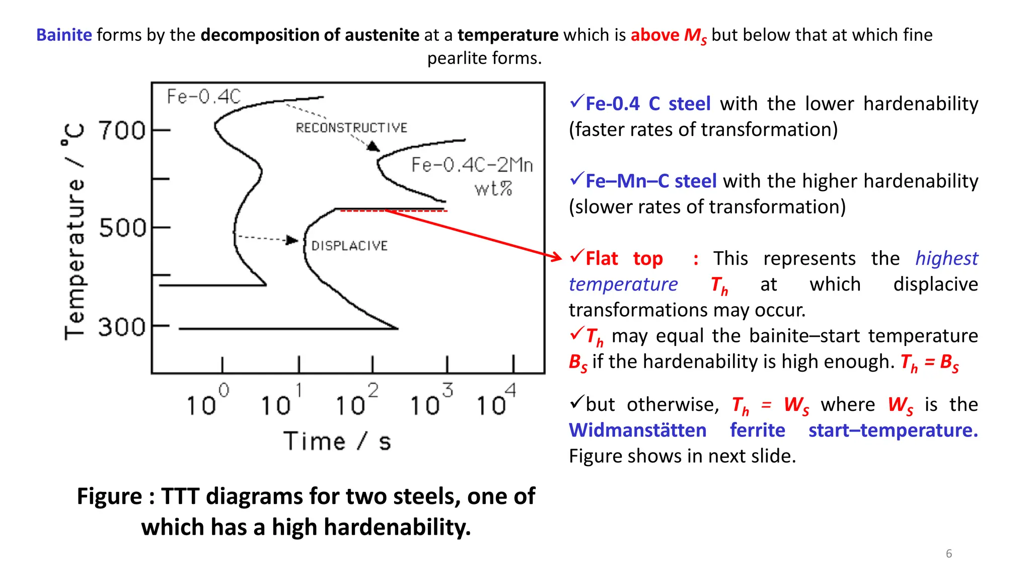
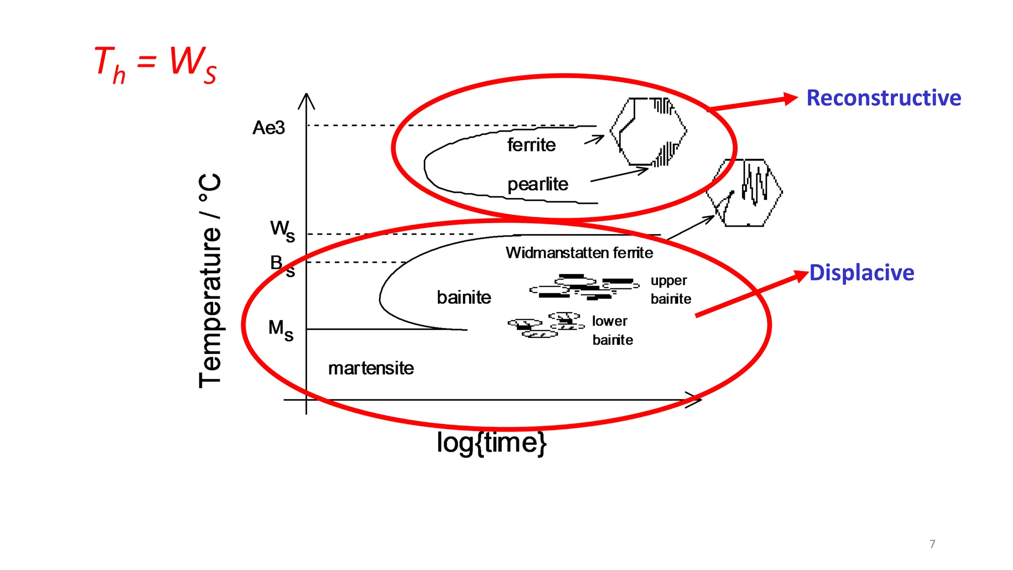
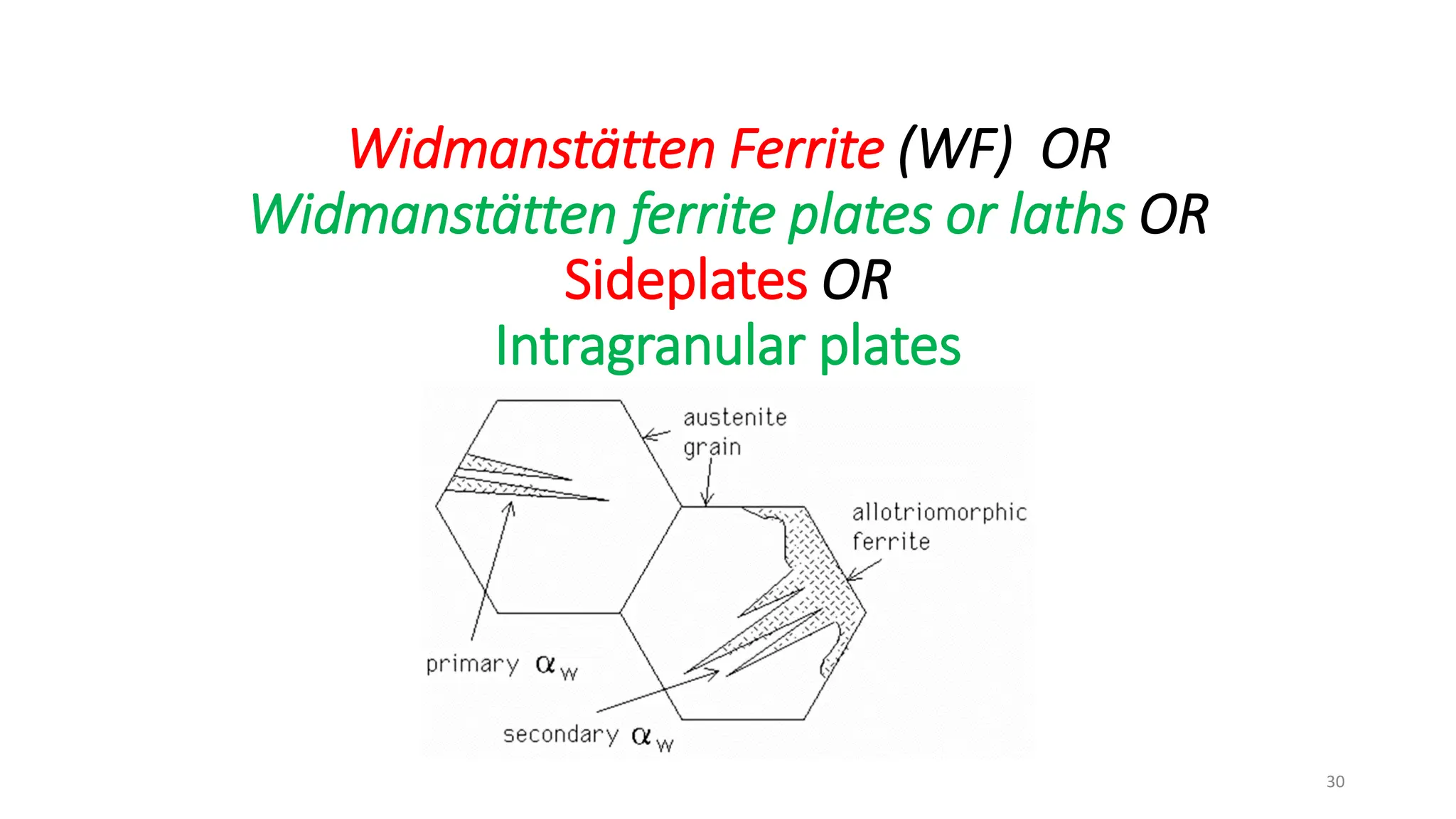


1) Phase transformations in solid metals include the decomposition of austenite into other phases such as bainite, Widmanstätten ferrite, and acicular ferrite. 2) Bainite forms by the decomposition of austenite at a temperature above the martensite start temperature but below the temperature at which fine pearlite forms. 3) Widmanstätten ferrite nucleates from austenite grain boundaries and grows in a displacive mechanism, maintaining an atomic correspondence between the parent and product phases resulting in a triangular shape. 4) Acicular ferrite forms as thin plates within prior austenite grains or as sideplates from grain boundaries


