This document provides a review of limit load solutions for structural components containing defects. It summarizes existing limit load solutions for plates, cylinders, spheres, pipe bends, and shell/nozzle intersections with various defect geometries under different loading conditions. The solutions are useful for failure assessment methods that utilize the limit load or reference stress concept. Experimental verification of some solutions is also discussed, along with factors such as material and geometric hardening effects.


![204 A. G. Miller
information about how defects should be characterized for the purpose of
assessing plastic collapse. However, it can be stated that if the defect size is
increased, the plastic collapse load cannot be increased, so circumscribing a
defect with a bigger effective defect is always conservative.
Miller t5 considered ductile failure test results for a variety of multiple
defect geometries and concluded that the code characterization was always
conservative. For purely ductile failure, net section area was a valid method
to use, and thin or multiple ligaments did not need any special treatment
except for that described in Section 1.8.
The limit solutions available in the literature for notched plates consider
the geometries with a finite root radius, or a V-shaped notch with any given
flank angle. The stress intensity factor is only relevant for sharp, parallel-
sided notches, and in practice defects are characterized for assessment
purposes as being of this form.
1.10 Yield criteria
The most c o m m o n l y used yield criteria are Tresca and von Mises:
Tresca max {]0.2 - 0.3], ]0.3 - atl, 10.1- 0._,1}= %
2
Mises (0.~ + 0. 5 ...[_0.2) __ (0.20.3 + 0"30"1 -'{'-0"10.2) m 0.:,,
or (0.~1+ a~z + a~3) -{022033 + 0.330"11 "~-0.110"22) + 3(0.-~3+ air + 0.~2) = Cry
0.~ principal stresses 0"~j stress components ay uniaxial yield stress
It can be shown that the difference in limit load given by these yield surfaces
is
N/3 3
0"866L~t" = 2 L~I, <~ Lr~< L,~I. ~ < 5 5 L T = l ' 1 5 5 L T
where L r and Lxl are the Tresca and Mises limit load respectively. In practice
this difference is small compared to other factors, and the choice is usually
made on grounds o f convenience.
1.11 Yield criteria for plane stress and plane strain
The yield criteria for plane stress (a 3 = 0) and plane strain (% = 0) are shown
in Fig. 3.
For plane stress the yield surfaces are plotted by putting 0.3 = 0 in the
above yield surfaces, to give a hexagon (Tresca) or an ellipse (Mises) as in
Fig. 3. For plane strain the condition % = 0 implies that
(0.1 + 0.'2)
0"3-- 2](https://image.slidesharecdn.com/milerlimitload-121219203950-phpapp02/85/Miller-limit-load-8-320.jpg)
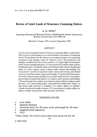
![Rerie,' ~I" limit loads o/'structures containing defects 205
PLone stroin
/
//
C[2,,. / Plane ~ ( ' ~ e'e
~" ,/Mises stress , ~,e~
, I: /,/¢"
, 2 "
IJ/,,"
"
t /
f#
Fig. 3. Plane stress and strain yield criteria.
and consequently Je~ - 02] is constant. It equals ay for Tresca and 1"155cr, for
Mises. The yield surface is thus two parallel lines as in Fig. 3.
As the plane strain yield surface circumscribes the plane stress yield
surface for both Tresca and Mises, the plane strain limit load is always
higher. Moreover, as the Mises plane strain surface may be obtained by
scaling the Tresca plane strain surface by a factor of 2/x/3, the limit loads are
in the same ratio. This increase in limit load is described by the constraint
factor c:
L
Tresca plane strain c=
LTo
L
Mises plane stress c=
/-'To
Mises plane strain c=
,/3L
2LT~
where L is the appropriate limit load and LT~,is the Tresca plane stress limit
load. Hence the two plane strain constraint factors are the same but the
plane strain Mises limit load is 1-155 times the plane strain Tresca load. It can
be seen from Fig. 3 that
1 ~< c ~ 1.155 Mises plane stress
whereas in plane strain the constraint factor is unbounded. The constraint
factor may also be regarded in tensile cases without bending as the ratio of
the average stress to the yield stress (or 1-155ay for plane strain Mises).](https://image.slidesharecdn.com/milerlimitload-121219203950-phpapp02/85/Miller-limit-load-9-320.jpg)


 z x < 0"295
o'rt 2
= [1 + 1"686x - 2"72x2](1 - x) z
1 - 0"31x x--*0
T h i s is an a n a l y t i c a p p r o x i m a t i o n to within 0"5% to the values given in
T a b l e 1. T h e results are s h o w n g r a p h i c a l l y in Fig. 6.
2.1.4 Plane strain Mises
T h i s is 1"155 times the p l a n e strain T r e s c a result.
2.2 S E N T tension ( M = 0, pin loading)
2.2.1 Plane stress Tresca 22
N
- n(x) = I-(1 - x) 2 + x23 ~/2 - x 0~<x~<l
tTyt
= [1 - 2x + 2 x 2 ] 1/2 - X
n ~ 1 - 2x x~0
y2
n ....~ _ _ y-,0
2](https://image.slidesharecdn.com/milerlimitload-121219203950-phpapp02/85/Miller-limit-load-13-320.jpg)

![Review of limit loads of structures containing defects 211
This is the same as in the plain b e a m result f o r c o m b i n e d tension a n d
bending, with the m o m e n t given by the eccentric tensile force o n the
ligament:
Na
M=
2
2.2.2 Plane stress Mises 22"z3
Deep cracks
N_N_=n(x)=[-[ " )'-- 1'~ 2 _ x ) Z ] l/z f 7--1'~
.., Lt-.+--r-) +7(1 - t?x--~--) x >0"146
= --7(l+y)x+v(l+v)x 2 -- 7x--
7y 2 2
for y - ~ O n~ 1 +7=0.536y2 7 - - - ~ r ~ = 1.155
I f 7 is put equal to unity, the Tresca result is recovered.
Shallow cracks
N
= n(x) = 1 -- x -- x 2 x < 0"146
o'rt
T h i s is an a p p r o x i m a t i o n to the t a b u l a t e d results in E w i n g and
R i c h a r d s 2z'za agreeing to within 0-15%:
n-+l -x x--*0
2.2.3 Plane stra& Tresca
D e e p cracks 22'z3
N
- - = n = 1-702{ I-(0-794 - 392 + 0"58763 ,2] 1/2 - [-0-794 - y]} x > 0.545
O'yl
n ~ 0"6303 '2 y~0
Shallow c r a c k s z4
N
-- n(x) x < 0.545
• o'yt
where
n(x)/> 1 -- x - 1.232x 2 + x 3 - f ( x )
and
n(x) ~ f ( x ) + 22x3(0.545 - x) 2
n ----~ 1 - - x x~0](https://image.slidesharecdn.com/milerlimitload-121219203950-phpapp02/85/Miller-limit-load-15-320.jpg)
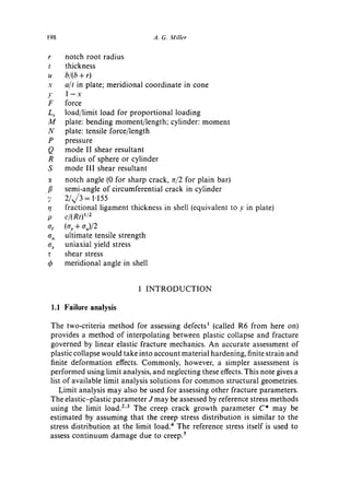
![212 A. G. Miller
The pin-loaded limit forces are shown graphically in Fig. 7. This also
shows the results of plane stress tests on mild steel specimens by Ewing and
Richards.22"23
2.2.4 Plane strain Mises
This is 1"155 times the Tresca plane strain result.
2.2.5
K u m a r et aL 25 give values for the limit loads which are the Tresca plane
stress results renormalized to give the correct result as x ---, 1. They are not the
correct limit load and are not recommended for use. The variation of their
h(n,x) functions with n would be reduced if they were normalized with
respect to the correct limit load as a function of x. (If reference stress theory
were exact, the variation would vanish.)
2.3 SEN tension with restrained rotation (fixed grip)
2.3.1 Plane stress Tresca and Mises, and plane strain Tresca
N
~yt
For Tresca plane stress this result may be derived by putting M = -½Na
into the expressions given in Section 2.4. The negative moment, shallow
crack combined bending and tension solution is not available for the other
cases, however.
This is compared with the pin-loading results in Fig. 7.
Z0
i
1.0 ',~ ---Io It U--19- o l -
I. l J
P Tresca plane strain ] Pin-
0.8
~"~,C,,._ M Mises 1 -. ~ loading
N e~'" T Tresco t wtane|
O'yt 06
~ Ist~ess/
~'~ ~" ~,F • Experimental J )
~',,~ "% ~ . _F_ PLanest.,s~ onO rres=o plan*
0/*
0.2
0 I l I L, I l l F ~ "~"'~I
0.1 0.2 03 0.~, O.S 06 0.7 08 0.9 I0
alt
Fig. 7, The theoretical and experimental variation of yield load with notch length for single-
.
edge notched (SEN) specimens (from Ewing and Richards ....~3 ).
~](https://image.slidesharecdn.com/milerlimitload-121219203950-phpapp02/85/Miller-limit-load-16-320.jpg)
![Review o[ limit loads of structures containing defects 213
2.3.2 Platte strain M i s e s
This is 1"155 times the Tresca plane strain limit load.
2.4 SEN combined tension and bending
This case may be derived from a transformation of the pin-loaded results, by
a method suggested by Ewing. 22"23 Equivalent results are given by Rice 26
and Shiratori and Dodd. 2~ Proportional loading is assumed. The results are
only valid for deep cracks. The signs are positive for forces and m o m e n t that
tend to open the crack. The effect of crack closure has been ignored:
applied load
Lr = limit load (in R6 Rev. 3 notation with limit load based on or)
( t -- a) N
3'~ - 2 M + N t (for M = 0, y, = 3')
(2M + Nt)q(y~) ),2 N
Lr = crr(t -- a) z q(Y~) n(y~) n(.v) = --tryt
where n is the appropriate function (Tresca or Mises plane stress or plane
strain) taken from Section 2.2 for the pin-loaded case and ),e is the effective
fractional ligament thickness as defined above.
It follows from this that in all cases the results in Section 2.1 obey
4M
°'rt 2 * 2nO') as ) , ~ 0
That is, the tensile force for very deep cracks is governed by the m o m e n t due
to the eccentricity of the ligament.
These results may be rewritten in terms of the m o m e n t referred to the
centre-line of the ligament:
M' = M + Na/2 L~ LGr(t _ a) 2 a,(t- a) q(Y~)
N/( t -- a)
)'e = ( 2 M ' ) / [ ( t - a) 2] + N / ( t - a)
This shows that only the stresses referred to the ligament affect the limit load.
The thickness t has no effect, provided that the crack is sufficiently deep. The
criterion for sufficient depth will now depend on the ratio N / M , and this
must be considered separately for each case. For Tresca plane stress the deep
crack solution is always valid. For Mises plane stress the shallow crack
solution is unknown. For Tresca or Mises plane strain the shallow crack
solution is discussed in Section 2.4.5.](https://image.slidesharecdn.com/milerlimitload-121219203950-phpapp02/85/Miller-limit-load-17-320.jpg)
![214 A. G. M i l l e r
2.4.1 Plane stress Tresca
The results m a y be written
2 M + Na + [(2M + Na) 2 + N2(t - a) 2] t2
Lr = O'y(t -- a) 2 0< x < 1
This is identical to eqn A2.4.4 in R6 Rev. 2. It is identical to the u n n o t c h e d
b e a m result:
V + - ? - =1
with a c c o u n t being taken o f the effect o f ligament eccentricity:
M---, M + Na/2
As the square root m a y have either sign, and plastic collapse m a y occur in
either tension or compression, the expression for L r m a y be rewritten
I2M + Na[ + E(2M + Na) " + NZ(t - a) z] 1/2
t r=
a~(t -- a) z
where now the positive square root sign is always taken.
2.4.2 Plane stress M i s e s
The a n a l o g o u s results apply. The deep crack validity limits are given by
O k a m u r a et al. 19
O.1540{l+N/[ay(t-a)]} if N
x> xo = - - <0"5475
1 + O'1540{N/[ay(t - a)]} ay(t - a)
N
x > x o < 0-220 if - - > 0"5475
o'y(t - a)
M !
cry (t -o )z .--.'_--_" Upper bound
Ewing a n d Richords
1.2-
" Lower b o u n d
Okomuro etal.
- ~"~."~=~'~ / o/t = 0 22
" V. ol t = 0.1
N~g.. o/t = 055
~N~. a / t = 0.0
%
V I I I 1 I I 1 I 1 I i I 1 t I I i I~ I
-lO -0.5 0.5 1.0
M= = M q.1/2No
Fig. 8. Limit moment and force for SEN plate (from Okamura et al. 1 9 ). Plane stress Mises.](https://image.slidesharecdn.com/milerlimitload-121219203950-phpapp02/85/Miller-limit-load-18-320.jpg)
![Review of limit loads of structures containing defects 215
This depth limit agrees with the value OfXo = 0-154 for pure bending given in
Section 2.1.2 at the validity limit:
N N
x=0-146 ~ = 0-832 - - = 0.974 > 0.5476
ayt ar( t -- a)
This therefore satisfies x 0 = 0.146 < 0-220 and is consistent with the above.
O k a m u r a derived lower bounds for shallow cracks. These are shown in
Fig. 8.
2.4.3 Plane stra& T r e s c a 24
The analogous results may be rewritten for deep cracks (where 'deep' will
be defined later) in terms of x = a/t:
~deep' cracks (in terms of Ye), i.e. bending-dominated
q(ye) = 0.794 - .re + [-(0.794 - 3,)2 + 0.588y2] 1/2 y, < 0"455
"shallow' cracks (in terms of yo), i.e. tension-dominated
q(y~) ~< v~ > 0"455
y~ -- (re + 0"232)(1 -- ye) 2 "
q(Y~) > y2
Ye -- 0', + 0"232)(1 --y,)2 + 22(1 - - ) ' e ) 3 ( y e -- 0"455) 2
These expressions are shown in Fig. 9.
The crack depth limit is given by
N 6M
x>0-4 x>0 M=0 x>0-295 N=0
l 12
The transitional value of 0"4 is the m a x i m u m for all values o f M / N t (i.e. the
deep crack solution is valid for all M / N t if x > 0.4).
Ewing's expressions were developed for the positive tension, positive
bending quadrant. The solution for all sign combinations is shown in Fig. 10
for deep cracks.
An alternative representation of the bending-dominated r6gime is given
by Shiratori and Miyoshi: 29
m " = 1-26 + 0.521 n" - 0-739(n") 2 0 ~< n" ~ 0"551
where
4M' N
a,(t - a) 2 a,(l - a)](https://image.slidesharecdn.com/milerlimitload-121219203950-phpapp02/85/Miller-limit-load-19-320.jpg)


![218 A. G. Miller
Table 2 are slightly lower than the values taken from Table 1, as they should
be.
2.5 SEN approximate solutions for combined tension and bending
2.5.1
R6 Rev. 2, eqn A2.4.5, gives an empirically modified version of the Tresca
plane stress result:
II'5M + Nal + [-(l'5M + Na) 2 + N2(t - - a ) 2 ] 1/2
Lr = o'y(t - - a ) 2
This expression is no longer recommended. It is 6% non-conservative
under pure bending compared to Tresca plane strain but conservative under
combined tension/bending.
2.5.2
The classical plate formulae are pessimistic because they assume that the
ends are free. An approximation sometimes made, 3t'32 or in O R A C L E by
Parsons, 33 is to ignore the contribution to the bending moment produced by
the eccentricity of the tensile force:
Met f = M -- ½Na
This cannot be rigorously justified, and it should be confirmed that
redistributing the moment ½Na does not cause another part of the structure
to be in a more onerous condition than the ligament. This version is used by
O R A C L E for both the Tresca plane stress formula and with the R6 Rev. 2
modification of this.
BS PD6493 uses the Tresca plane stress version of this approximation.
2.5.3
Chel132 gives an approximate solution for plane strain which is equivalent to
the solution here for deep cracks, and is based on a conservative
approximation to the pin-loading SENT results when a/t < 0"545.
2.6 SENB pure bending: effect of notch angle
2.6.1 Plane stress Tresca
The constraint factor is unity, independent of notch angle 2:~:
4M
O.rt2(1 __ X) 2 = 1
C -------](https://image.slidesharecdn.com/milerlimitload-121219203950-phpapp02/85/Miller-limit-load-22-320.jpg)


![226 A. G. Miller
CT5 1
I
!t
[ , SEN -
O SEN-----
I Lood Line
t
Fig. 17. Compact-tension specimen geometry.
2.11.1 Plane stress Tresca
n(x) = - ( 1 + x) + (2 + 2X2) l '2 l>x>0
x--* 1 n ---~y2/4
2.11.2 Plane stress Mises
n(x) = - ( ~ x + 1) + [(Tx 2 + 1)(1 + ;,)] ~/2 for l > x > 0
2
y= ~ = 1.155
1.072v 2
x~ 1 n ~ 0.268y 2 = 4
2.11.3 Plane strain Tresca
n(x) = - ( 1 + 1"702x) + [-2-702 + 4"599x 2] 1/2 for 1 > x > 0.090
x~ 1 n ~ 0"315y 2 - 1"260)'2
4
These results are s h o w n in Fig. 18.
2.11.4 Plane strain Mises
This is 1"155 times the plane strain Tresca limit load.
2.11.5
K u m a r et al. 25 give values for the limit loads which, as in the p i n - l o a d e d
S E N T case ( S e c t i o n 2.2.5), are the T r e s c a p l a n e stress f o r m u l a e ,](https://image.slidesharecdn.com/milerlimitload-121219203950-phpapp02/85/Miller-limit-load-30-320.jpg)


![232 A. G. Miller
Upper B o u n d
(Notched Cantilever)
Bound
M/M Nominc]| L o w e r B o u n d
(M2/M2~.Q2/Q2=1)
I
Lower Bound
8/w 2
0"6
O.t,.
0"2
0
I I I
2/.
I I I
~l
02 or, 06 o-8 1
Q/Q1
Fig. 22. Combined bending and mode II shear (from Ewing and Swingler43).
crack depth. The upper bound is potentially exact for Q/Q ~ > 0-803 (i.e. the
slipline field is statically admissible, but it has not been constructed in full).
When Q = 0, the solution coincides with that given in Section 2.1.3.
If the notch is at a cantilever position, then the limit moment is higher, and
is also shown in Table 8. The depth validity limits for these results have not
been calculated.
The Mises load is a factor of 1"155 greater.
2.13.4
A c o m m o n approximate solution for combined tension, bending and mode
II shear is to generalize Section 2.4.1 to include shear in a Tresca yield
criterion:
~° = b2 +~ b2 +L b~ ) + 7 Lr=--~y
This is similar to Section 2.12.1 with a h = 0, Tresca shear instead of Mises
shear, and an amelioration allowed for the effect o f the crack on the collapse](https://image.slidesharecdn.com/milerlimitload-121219203950-phpapp02/85/Miller-limit-load-36-320.jpg)


![236 A. G. Miller
TABLE 9
Centre-cracked Plate in Tension (values given in units of a/'~,)
(plane stress Mises)
a't h/t
0.2 0.4 0.6 >.0.71
o-l 0.650 0-753 0.900 0.900
0.2 0.390 0.654 0.800 0.800
0.3 0-230 0.530 0.646 0.700
0.4 0.145 0.425 0.538 0-600
0.5 0.100 0.312 0-427 0-500
0.6 0.076 0.225 0.338 0.400
0.7 0.065 o. 160 0.270 0-300
0.8 0-049 o. I 17 0-200 0.200
0.9 0.027 0.090 o-I oo o-I oo
3.1.1 Plane stress Tresca aJld Mises, a n d p l a n e strain Tresca
N=ay(t-a) (Ref. 16)
This is c o m p a r e d with experimental results in Fig. 27, taken from
Willoughby.17
This result is not valid for short plates (h << t). H o d g e ~6 d e m o n s t r a t e d that
it was exact for square plates (h = t). A i n s w o r t h (pets. comm.) derived an
a p p r o x i m a t e lower b o u n d solution for the case of a uniform applied stress.
This agreed with the above solution when h 2 > _ . 2 a ( t - a ) . This is always
satisfied if h/t > l / x / 2 = 0"707.
The results for short plates from Ainsworth's lower b o u n d m e t h o d are
s h o w n in Table 9 for plane stress and Mises yield criterion.
3.1.2 Plane strain M i s e s
This is 1'155 times the plane strain Tresca result.
3.2 Eccentric crack under tension and bending
3.2.1
A lower b o u n d solution which reduces to the Tresca plane stress result is, for
M - ae M (t 2 - a z - 4e 2)
(a) Nt >~t(t-a~ and ~/> 8et
M - ae M (t 2 - a 2 - 4e 2)
or(b) Nt <<'t(t-a~ and N-t~< 8et
]M + aN/2l + [(M + aN~2) z + N 2 { ( t 2 - aZ)/4 - ae}] 1 ,
Lr = 2~y[(t 2 - a2)/4 - ae]](https://image.slidesharecdn.com/milerlimitload-121219203950-phpapp02/85/Miller-limit-load-40-320.jpg)
![Reriew O/ limit loads t?]'struc'tures containing defects 237
1.2
1.0
, , , .
N 0.8~ N ~ !!el
°
0.6
0.¢.
0.2
0
0.2 0.4 0.6 0.5 1.0
a/t
Fig. 2"/. Centre-cracked panels in tension (from Willoughby I ~). All data from Table 9. ©,
A533B steel; /~, 316 stainless steel plate; A, 316 stainless steel weld; (3, low alloy steel.
Alternatively, for
M - ae M (t 2 - a 2 - 4e 2)
(a) N t >" t(t - a-----) a n d N-t ~< 8et
M -ae M (t 2 - - a 2 -- 4 e 2)
or (b) N t <<"t(t--a----~ a n d ~/> 8et
IM- aN~21 + [ ( M - aN~2) z + NZ{(t 2 - a2)/4 + ae}] l'z
Lr = 20"y[(t 2 - a 2 ) / 4 + ae]
The geometry is shown in Fig. 26. The eccentricity e is assumed to be
positive. A positive bending m o m e n t , M, is one which tends to produce
tension at the surface closer to the crack. The positive square root sign is
taken. The choice o f f o r m u l a depends on which ligament the neutral axis is
in.](https://image.slidesharecdn.com/milerlimitload-121219203950-phpapp02/85/Miller-limit-load-41-320.jpg)


![Review of limit loads of structures containing defects 241
3.2.4
Ewing ~° has considered an eccentric defect in anti-plane shear, as shown in
Fig. 29. The following quantities were calculated:
q. stress required to spread plasticity across shorter ligament, assuming
strip yielding model
rLE value of v~. estimated from elastic stress resultants
rG stress needed to spread plasticity across both ligaments (constraint
factor is unity)
The same numerical results apply to the mode I tensile analogy shown in Fig.
30, and may be considered as an approximation to the mode I loading of a
single strip with an eccentric defect.
3.3 Eccentric crack under tension, bending and out-of-plane loading
The lower bound solution in Section 3.2 may be generalized to include out-
of-plane tension and shear (but not out-of-plane bending). The geometry is
shown in Fig. 26. Free surface shear stress effects have been ignored (see
Section 2.12). Let
N' = N- 1/26h(t - a) M ' = M + l/2ahae
Then
(a~ + 3/4a~ + 3r2) t~z
Lr m (with a Mises shear term)
O'y
where
M ' + aN'~2 + { ( M ' + aN'~2) 2 + {N')2[(t -' - a2)/4 - ae]} l'z
a~ = 2[(t 2 - aZ)/4 - ae]
a. is the out-of-plane tensile stress and r-" is the sum of the squares of the
shear stresses.
For the assumed stress distribution to be valid
N'>O M'>O
For a~ = r = 0, this reduces to the solution given in Section 3.2.1.
3.4 Embedded elliptical defect in tension
The only results known to the author are those for the local ligament
collapse load for a central elliptical embedded defect in a plate in tension
given by Goerner. 4s A simplified strip yielding model was used, and the
calculated load was the load at which yielding first extended across the
ligament at the thinnest point. The calculations are analogous to those for
surface defects quoted in Section 5.1.3, and the results are shown in Fig. 31.](https://image.slidesharecdn.com/milerlimitload-121219203950-phpapp02/85/Miller-limit-load-45-320.jpg)


![244 A. G. Miller
4.2.5
K u m a r et aL 2s give formulae which are not the correct limit loads. These
results are not recommended for use.
4.3 Combined tension and bending
The general solution for combined tension and bending is not known. A
lower bound solution, exact for Tresca plane stress, may be obtained by
applying the Tresca plane stress solution for plain beams to the reduced
section width:
[2M[ + [ 4 M 2 + N 2 ( t - 2a) 2]~ '
L r =
ay(t - - 2 a ) 2
For a given ligament thickness and ligament load, the single-edge notched
solution will be a lower bound to the double-edge notched case.
4.4 Bending: effect of notch angle
4.4.1 Plane stress Tresca
4M
-1
o'y(t -- 2a) 2
4.4.2 Plane stress Mises
Not known but 1 ~<c~< 1"155.
4.4.3 Plane strah7 Tresca z°
¢--
4M
Cry(t -- 2a) 2
Deep cracks
0<:(<30 ~ c = 1.380
30 -~< ~ < 73.6 ° c = 1"380 - 0.280(:( - 7z/6)a to 0"2%
73.6 ° < x < 90 ~ c= 1+r~t2-~
Green's results are upper bounds. The intermediate range of:t equation is a
numerical fit to his bound. This merges continuously with the deep sharp
crack result at ~ = 0 (c = 1"380) and the unnotched bar result at ~ = rt/2. The
depth validity limits are unknown. The results are shown in Fig. 33. Dietrich
and Szczepinski 35 give the complete slipline field for ~--75 ~, and their
constraint factor is the same as above.
4.4.4 Plane strain Mises
This is 1"155 times the plane strain Tresca limit load.
A discussion o f combined tension and bending in plane strain for large
notch angles and deep cracks is given by Shiratori and Dodd. z7](https://image.slidesharecdn.com/milerlimitload-121219203950-phpapp02/85/Miller-limit-load-48-320.jpg)

![246 A. G. Miller
m
1.3
u
°1.2
C
0
C
0
1
0 .1 .2 .3 ,t. .5 .6 .7 .8 .g 1.0
b
b+r
Fig. 34. DENB with circular root: plane strain (from Green-'°).
4.5.4 Plane strain Mises
This is 1"155 times the plane strain Tresca limit load.
A discussion of c o m b i n e d tension and bending in plane strain for large
root radii and deep cracks is given by D o d d and Shiratori. 3~
4.6 Tension: effect of notch angle
4.6.1 Plane stress Tresca s~
N
e --1
ay(t - 2a)
Hill showed that the constraint factor is i n d e p e n d e n t o f notch shape.
4.6.2 Plane stress M i s e s 49
N
C=
ay(t -- 2a)
< 70"5 ° shallow c = 1 + l'08x 0<x<0"143
deep c = 1-155 0.143 < x < 0.5
c~> 70-5 ° shallow c = 1 + 1.08x 0 < x < 0-143 sin [(re/2 - :0, 0.217]
deep c = 1 + 0.155 sin [(rc/2 - ~)/0.217]
0"143 sin [(rc/2 - e)/0"217] < x < 0"5
(:~ in radians)
These are a p p r o x i m a t i o n s to numerical results. The deep crack results were
given by Hill 5~ a n d F o r d a n d Lianis. ~8 The results are identical with the
sharp crack results for ~ < 70.5 °, and give the u n n o t c h e d bar results for
= re/2. The results are s h o w n in Fig. 35, with b o t h upper and lower bounds.](https://image.slidesharecdn.com/milerlimitload-121219203950-phpapp02/85/Miller-limit-load-50-320.jpg)

![248 A. G. Miller
1.15
Hill's upper b
o
1.10
//~. Lower.
e- 1 . 0 5
o
1.0 I
0 0.1 0.2 0.3 0.4 O.S 0.6 0.7 O.S 0.9 1.0
b
b÷r
Fig. 36. DENT with circular root: plane stress Mises (from Ford and LianisLS).
results. T h e y merge with the deep s h a r p n o t c h solution at r = 0 ( c = 1"155)
and with the u n n o t c h e d b a r solution at r = vc. T h e d e p t h validity limits are
not k n o w n , except at r = 0 and r = c~. T h e results are s h o w n in Fig. 36, with
b o t h u p p e r a n d lower bounds.
4.7.3 Plane strain Tresca 5z
N
c- /. = min [7z/2, In (1 + b/2r)]
ay(t - 2a)
deep n o t c h e s (exact)
t > b(2e z - 1) - 2r(e ~ - 1) 2
small b/r:/. = In (1 + b/2r)< ~/2 angle at n o t c h that has yielded
c = (1 + 2r/b)ln(1 + b/2r)
This result was given by Hill: 53
large b/r: In(1 + b/2r) > 7t/2
c = 1 + ~/2 -- 2r/b(e ~"2 _ 1 - ~/2)
shallow notches ( a p p r o x i m a t e )
t < b(2e z - I) - 2r(e z - I) 2
( 2r 2rt"l'/2 (~_rr) [ b b( 2r 2rt'~] '/2
c= 1+ b b2 j + 1+ In l+2r-2r 1+ b t,-'J_]
W h e n r = 0 the solution is identical to that o f Ewing and Hill 5° for s h a r p
notches, b o t h d e e p and shallow. F o r u n n o t c h e d bars
r= m Z=0 tc=b
T h e deep n o t c h solution gives c + 1. T h e shallow n o t c h solution limit](https://image.slidesharecdn.com/milerlimitload-121219203950-phpapp02/85/Miller-limit-load-52-320.jpg)
![Review of limit loads of structures containing defects 249
depends on the order in which the limit is taken, but gives c ~ 1 if r--, oc is
taken last. Ewing 52 also gives the effect of ~ > 0.
4.7.4 P l a n e s t r a i n M i s e s
This is 1"155 times the Tresca plane strain limit load.
4.8 Staggered notches under tension with restrained rotation
Connors s4 gives an approximate solution for the geometry shown in Fig. 37,
with the notation:
a = crack depth (cracks of equal depth)
d = crack separation
t = plate thickness
N 0 = fly/
Ny = limit load
Ny = min (Ni, NH)
a r i d 2 + (t -- 2a) z]
N~ = [ 3 d 2 + (t - 2a) 2] t/2 using the Mises yield criterion
N, is the pin-loaded S E N T result from Section 2.2. The experimental results
are shown in Fig. 38 for the limit load based on a deformation criterion.
For d = 0 this reduces to the Tresca plane stress D E N T solution (despite
the use of the Mises yield criterion).
4.9 Combined bending and mode II shear
This has been calculated for deep cracks in plane strain by Ewing and
Swingler. 43 The results also apply to the case where the cracks are at a
cantilevered end. Lower and upper bounds are shown in Table 10 and Fig.
39. The 'nominal' yield criterion is also shown:
+ =1
M1 = ~,(t -- 2a)2/4 (Tresca) Q1 = cry(t- 2a)/2
This is within 5% of the lower bound.
The upper bound is potentially exact, but is an incomplete solution. In the
zero shear limit, it agrees with the solution given in Section 4.1.3. The depth
validity limits are also shown in Table 10. They are reduced by shear.
The Mises limit load is greater by a factor of 1.155.](https://image.slidesharecdn.com/milerlimitload-121219203950-phpapp02/85/Miller-limit-load-53-320.jpg)

![Review o f limit loads o f structures containing defects 251
Upper Bound
M/MI
Nominal Lower Bound
I .(M21MI 2 ÷ O21012--1)
Lower Bound
8/~ 2
0-6
o., -
0.2 !- '1
j 2/~ 1
o i i I ] i
0-2 0"~ 06 0-8 I
Q/Q1
Fig. 39. Combined bending and mode II shear (from Ewing and Swingler~3).
TABLE 10
Combined Bending and Mode II Shear
(from Ewing and Swingler43)
O/O, Upper Depth Lower Q,"Q I Upper Depth Lower
bound limit bound bound limit bound
M/M t 2a/t M/M 1 M/M t 2a/'t AI/M t
0-000 1'380 0"336 1"000 0-550 1-020 0-051 0"875
0"050 1-358 0"314 0"999 0'600 0"970 0'028 0"842
0"100 1'334 0"290 0"997 0"650 0"915 0"011 0.797
0-150 1-308 0'266 0-992 0-700 0-854 0-001 0"736
0'200 1-281 0-241 0'986 0-750 0"786 0-657
0'250 I "251 0-215 0'978 0-800 0"708 0-56 I
0-300 1"220 0-188 0"968 0-850 0-618 0.447
0-350 I' 185 0" 160 0"956 0'900 0-509 0"315
0"400 1"149 0"132 0"941 0"950 0"362 0"166
0"450 I" 109 0' 104 0"923 ! "000 0-000 0"000
0-500 I "067 0.077 0'902](https://image.slidesharecdn.com/milerlimitload-121219203950-phpapp02/85/Miller-limit-load-55-320.jpg)
![252 A. G. Miller
M
_.U
n
t
l Iut°'t,
b /N )
M
I ..... +
1
Fig. 40. Asymmetric double-edge notched plate.
4.10 Combined tension, bending, mode 11 shear and out-of-plane stress
The solution given by Jeans, 43 quoted in Section 2.12.1, is a true lower b o u n d
for this case (with uniform out-of-plane tensile stress across the section).
4.11 Combined tension and bending: asymmetric notches
The geometry considered is shown in Fig. 40. Ewing (pers. comm.)
constructed a Tresca plane stress lower bound solution as follows. With
notation as in Fig. 40
Mt = M + Nat/2
is the moment referred to the middle of ligament h I (= t - at). Assuming that
the cracks are able to support compressive stress, then
L r = [ 2 M t + (4M/- + N 2 h~) 1 2 ]/(ay/-,t)
"~ "~ 2 ,
provided that the compressive region is at least as deep as crack a_,. The
height h of this region satisfies
- h a y + (h t - h)cTy= N~.om,p~c= N,/L r
so that
2h = h t - N / L , a y ~> 2a_, (26)
a;t 'tl
N
t r
bl
dl
+ d2
:x: (in c o n t a c t )
t J ~c12
Fig. 41. Asymmetricdouble-edge notched plate alternative solution.](https://image.slidesharecdn.com/milerlimitload-121219203950-phpapp02/85/Miller-limit-load-56-320.jpg)
![Review of limit loads of structures containing defects 253
Ifeqn (26) fails, ignore material below some ligament 'b' lying between b~ and
i.e. solve for b and L r the simultaneous equations
b~ - a z,
L r = {2M" + [ 4 M ''2 + N 2 b 2 ] t / 2 } / u y b 2 b = 2a~ + N/Lray
where
a'~ = a z - b I + b M " = M I - N ( b I - b)/2
Alternatively, for very deep cracks a2 in compression, assume that only the
outside part 'x' is compressed and that the system is equivalent to an internal
crack (see Fig. 41). At collapse
N/L r = ay(bt - a2 - x ) M/Lr = ¢ry[(bl - a2)dt + x d 2 ]
which can be solved for x and Lr as unknowns. This gives an alternative
lower bound.
5 S H O R T S U R F A C E C R A C K S IN PLATES
5.1 Wide plates in tension
Ligaments in finite length cracks are stronger than ligaments in extended
defects, as they derive support from the adjacent uncracked plate. If
ligament failure is the subject of concern, then this 'local' limit load goes to
zero as the ligament thickness goes to zero. This is in contrast to the 'global'
limit load, which would tend to the through-cracked plate limit load (as in
Section 3) as the ligament thickness tended to zero. Moreover, for wide plates
(width >>defect length) the defect has no effect on the global limit load.
a defect depth (see Fig. 42)
2c defect surface length
t plate thickness
W
2c P
Fig. 42. Geometry of surface defect.](https://image.slidesharecdn.com/milerlimitload-121219203950-phpapp02/85/Miller-limit-load-57-320.jpg)
![254 A. G. Miller
1.0 D
0.8
0.~ 0.5
/'~)e f f
, , ,
0 0.2 0 :, 06 0.8 1.0
(li t
Fig. 43. Ligament correction parameter as a function of a/t (from MilneSS).
5.1.1
R6 Rev. 2 recommends that short surface cracks may be treated as extended
defects with an equivalent depth given by
__
0.1 < 2--~< 0.5
o 2t(2c+ t)
O<ff<0.8
t
(t)e=-at --2ca<0"1
No guidance is given for deep defects with a/t > 0"8. This is shown in Fig. 43.
(There is a misprint in Fig. A2.2 in R6 Rev. 2 in the inequality limits.) There is
not a smooth transition between short defects and extended defects, and the
recommendation is arbitrary.
5.1.2
Chel156 proposed a transformation
a[ 1 - ( l/f)] where f = (1 +~-)2cZ'~1'2
ae = 1 - (a/tf ) <~ a
for extended cracks (c = oo) ae=a
for zero length cracks (c = 0) ac=0
for through cracks ae=a=t](https://image.slidesharecdn.com/milerlimitload-121219203950-phpapp02/85/Miller-limit-load-58-320.jpg)
![Review of limit loads of structures containing defects 255
He proposed that this formula applied to all geometries, not only plates. This
transformation is analogous in form to the Battelle formulation in Section
8.2.3, which may be written
a[ 1 - (l/M)]
ae = 1-(a/tM)
where M is a function of both c/t and R/t (R is the cylinder radius):
C2 '~1/2
M- 1 + 1"05~-~-,/
CheWs transformation gives a lower limit load for cylinders than the Battelle
transformation, as f > M. This transformation is the simplest rational
function with the above three properties.
5.1.3
Mattheck et al. 57 propose an expression for ligament yielding based on
Dugdale model calculations. Their expression is tr = arM, where
M = (1 - I - 1.9071 1 + 1.5151(a)°'16596(/)2
1 52(a']214'O(a'] 3
1
x [ - 0.74 + 3.855 a - 3.825(a)2 - 2.89(a)3
+ 4"356(ayl}[1- (t)"4° 1
This equation can be applied for a/c < 0-7; ~r is applied membrane stress.
This formula is shown in Fig. 44(a) and compared with their detailed
numerical results. The results are compared with the above expressions from
R6 and Chell in Fig. 44(b). It can be seen that in general the Mattheck result
is most conservative and the R6 Rev. 2 result is least conservative. The R6
result has been plotted beyond the claimed validity limits for a/t.
5.1.4
Miller 9 derived a semi-empirical model for ductile failure (i.e. at L m~x) of
surface defects and concluded that the reference strain at failure was
k t 1-a/t
4 c a/t](https://image.slidesharecdn.com/milerlimitload-121219203950-phpapp02/85/Miller-limit-load-59-320.jpg)

![Review of limit loads of structures containing defects 257
(i- ~-)z =~i (÷)
(~.)z
2[ mm
mb= bm
bb
oI [ I I I I
o 0.2 O.t, 0.6 0.8 1.0
OIt
Fig. 45. Spring compliance (SEN).
a n d ~ is s h o w n in Fig. 45. ~ m a y be c a l c u l a t e d f r o m f o r m u l a e g i v e n b y
E w i n g : 5s
x =- a/t y -- 1 -- x ~ij = nlij
I m m ( x ) = O ' 6 2 9 4 4 x 2 ( l + 5"474xZ + 1 3 " 3 8 x 4 - - 3 2 x S + 58"32x6) ifx<0"5
= (0"629 4 4 / y 2 ) [ 1 -- 2"944)' + 1"0834y 2 In (1/2y) + 2"667) '2] if x > 0"5
Imb(X) = 0"209 8 lx2(3 - 2"4x + 9"487x 2 + 43"4x 3 -- 142"07x 4
+ 173"6x 5 -- 27"89x 6) if x < 0"5
= (0"209 81/)'2)(1 -- 1"4723' + 0"370 6 4 y 2) if x > 0"5
lbb(X) = 0"069 938xZ(9 -- 14"4X + 46"98X z -- 46X 3 + 89"02X 4
-- 184X 5 + 193"9X 6) if X < 0"5
= (0"069 938/y2)(1 -- 1"3404) '2) if X > 0"5](https://image.slidesharecdn.com/milerlimitload-121219203950-phpapp02/85/Miller-limit-load-61-320.jpg)

![Review of lirnit loads of structures containing defects 259
5.2.1
A review of CEGB and Welding Institute test results is given by Miller. 59
The degree of gtrain hardening is observed to increase with increasing
ligament thickness.
Miller 59 gives the nominal strain at failure as
kt(t - a)
4ca[ 1 - (2c/w)] "
w plate width
k material constant ~0.4-1-5
A lower bound to the final plate failure load after ligament snap-through
is given by F = a,A o, where A o is the net-section area without the ligament.
5.2.2
Hasegawa et al. 6° observed a similar increase with ligament thickness of the
net-section stress at the onset of crack penetration. They empirically put the
ligament stress cr~ and the stress cr~ in the rest of the plate as
~rl = (1 - R)crf (R = reduction of area in tensile test)
tro = tru - (a. - ar)(a/t)
A lower bound to the final plate failure load was given by
F = A o m i n l a , , a f + ( a . - O'f)( 1 --a/t~210"9
}_]
which is slightly lower than that given in Section 5.2.1.
5.2.3
Mattheck and Goerner 6t used a strip yielding model where the stress along
the crack front and along the ligament centre-line was a u, just before
ligament rupture, whereas the stress at the end of the plastic zone at the
surface is reduced to the yield stress. Although detailed results were not
presented, this will also give an increase of net-section stress with ligament
thickness. Agreement with ligament rupture test results was good.
5.2.4
Munz 62 gives a review of surface cracks. He also reports further plate tests
of Goering, which agreed with the hardening models of Sections 5.2.2 and
5.2.3, but where the maximum load was underestimated by using flow stress.
5.2.5
The above are concerned mainly with the ductile instability cut-off at Lr
max.
Miller t2 reviewed published J calculations for surface defects in plates in](https://image.slidesharecdn.com/milerlimitload-121219203950-phpapp02/85/Miller-limit-load-63-320.jpg)

![Reciew o/'limit Ioad~ 01 structures containing de/i'cts 261
C (Shield)
heotetical
2.6 -%,,curve 2=.
2.&
2.2 ~ f>p.
2.0
~. "%%.~ 2b Moteriol oluminium
1.8 "'~
16 f u ..L / %
. 0"~
1.4 % ~
1.2 '~'
1.0 J i I I I ~1 ,
15° 30" 45 ° G0" 75" 90 °
(7,.
Fig. 46. Theoretical and experimental values of the constraint factors. ©, Axial symmetry
calculated points: A , experimental ./;r points (yield point); ff], experimental fu.~. points
(ultimate load). (From Szczepinski et al. 65)
Fig. 47 and are slightly less restrictive than those give by Shield.
Experimental results are also shown in Fig. 46.
A lower bound that is within 4% o f the results in Fig. 46 is
F 3'7:~
c - - ~,rcb2 - 2"85 - -
a - (x in radians)
7~
An approximation to the depth requirement is
R 3-88:(
-- > 2"94 - - -
b ~z
6.3 Bar with axisymmetric round notch under tension
b minimum radius
r notch root radius
F axial force
R i b 3.0,
2.6
2.6
2. t,
2.2
2.0
1.8
1.6
1.4
1.2
1.0 .-.-.~-
0 30 e 60 ° 9 0 ° l z 0 " l S 0 t 180 •
Notch angle 20(
Fig. 47. Theoretical values of the R/b ratio for V-notched bars (from Szczepinski et al.65).](https://image.slidesharecdn.com/milerlimitload-121219203950-phpapp02/85/Miller-limit-load-65-320.jpg)


![Review of limit loads of structures containing defects 269
where 4) is the co-latitude, r o is the circle of latitude radius, r x is the
meridional radius of curvature and
1 dr o
rl------
cos 4, d4,
Hence, for an axisymmetric defect at 4,0 of depth a in a shell of thickness t,
the membrane lower b o u n d to the limit pressure is given by
P = 2ay(t - a) sin 4'0
go
This assumes that the defect is deep enough to determine the limit pressure,
and only applies if this pressure is less than the limit pressure of the defect-
free shell. The value of N0 at the defect does not have to be considered, as it
can be discontinuous.
For meridional cracks, the effect of the defect on the limit pressure is given
by the following constraints:
NO( 4'o) No( 4'o)
t t--a
max []aol, Io'0l, ]a, - a0l } ~< ay for Tresca
where 4'0 is the value of 4' along the defect that gives the lowest limit
pressure.
7.3 Approximate lower bound for part-through defect for pressure loading
If a lower bound limit pressure for a through-thickness defect and the
membrane limit pressure for a defect-free structure, of the same geometry,
are both known, then a lower b o u n d solution for the part-through-thickness
case may be determined. 73-~5 If the solutions are
lower b o u n d Pl[t] membrane Pm[t]
where these refer to the solutions for a shell of thickness t, then a lower
bound for the part-through-thickness case is
P = P,[a] + P m [ t - a]
It may be seen that this is compatible with a statically admissible stress field.
An alternative lower b o u n d approach, due to Goodall (see Millerg), is to
split the structure into the ligament and a through-cracked shell of the
original thickness t. Then a lower bound to the case when the ligament is in
pure tension is given by
P = P,[t] + Pm[t -- a]](https://image.slidesharecdn.com/milerlimitload-121219203950-phpapp02/85/Miller-limit-load-73-320.jpg)
![270 A. G. Miller
This is larger than the above expression, as
el[t] > Pl[a]
However, bending effects have been ignored, so strictly the result is only valid
for a single ligament position, whereas the first expression is valid for all
ligament positions.
These expressions give the global collapse load and may not be
appropriate (see, for example, Section 8.2.1 on surface axial defects in
cylinders).
7.4 Limit pressure for short through cracks
Goodalt 76 derived an approximate lower bound for the limit pressure of a
through-cracked shell using shallow shell theory, assuming that the
membrane stress state of the uncracked shell is known:
2c = crack length
R t = radius of curvature parallel to crack
R 2 = radius of curvature perpendicular to crack
p = c(R2t)- 1/2
N u = membrane stress produced by pressure P, parallel to crack for crack-
free shell
Then the limit pressure is given by
P = R 2 1 + p2 + R1 cryt/
provided 0 <~NH <<.ayt. For axial defects in cylinders this gives (as in Section
8.1.1)
P _ ayt 1
R l+p 2
For meridional defects in spheres it gives
P _ 2ayt 1
R l+p 2
8 C Y L I N D E R S WITH A X I A L D E F E C T S A N D R E C T A N G U L A R
NOTCHES
Only pressure loading is considered here. Test results for this were reviewed
by Miller. 77 Axial defects theoretically have no effect on the limit moment](https://image.slidesharecdn.com/milerlimitload-121219203950-phpapp02/85/Miller-limit-load-74-320.jpg)
![Review of limit loads of structures containing defects 271
for beam bending of the cylinder with respect to a diametral plane.
Experimentally there is a slight effect,vs Through-wall bending stresses are
not normally considered to contribute to the collapse load.
The recommendation of the empirical Battelle formulae in Sections 8.1
and 8.2 is based upon analysing burst pressure results where no allowance
was made for tearing. Therefore their use to evaluate the yield point load and
L r is an approximation.
8.1 Penetrating axial defects
8.1.1
Kitching eta[. 79 consider rectangular defects both experimentally and
theoretically. The material was mild steel. Their experimental loads were
determined by a deformation criterion, and are adequately explained for
axial defects by a limit pressure given by
P = ayt 1
R l+p 2 p>l
p=ayt I 2 ]
R 1 + ( 1 + 8 p 2 ) ~/2 +Cp p<l
where
c
R = cylinder radius
p = (Rt)l/2
2c = defect length t = cylinder thickness
C=0-12
C is a constant introduced because the experimental failure pressures were
higher than the theoretical pressures. (This might be due partly to the use of
¢zyrather than ~r.) The limit analysis comes from a lower bound solution for
rectangular holes using the two-moment limited interaction yield surface.
For a strict lower bound solution, C should be set equal to zero.
8.1.2
The most commonly used collapse formulation is an empirical expression
due to Kiefner et al. 8° at Battelle. This is based on an adaptation of Folias'
L E F M result:
PR 1 M(p) = (1 + 1"61p2) 12 (Folias sl)
~yt M(p)
or the revised version:
M(p) = (1 + 1"05p2) 1/2 (Folias s2)](https://image.slidesharecdn.com/milerlimitload-121219203950-phpapp02/85/Miller-limit-load-75-320.jpg)


![274 A. G. Miller
and a 'leak' results. For thicker defects, the through-wall defect is not stable
and a catastrophic 'break' results.
8.2.4
Ruiz 83 gave an approximate expression, but it is not recommended for use,
as it does not agree with other results in various limiting cases.
8.2.5
The above thin shell formulae do not distinguish between internal and
external defects, or between rectangular and semi-elliptical defects. There is
not adequate experimental evidence to judge these effects. Chel184 has
proposed empirical expressions for internal defects:
local ligament failure
PR q M(p,q) [1 + 1.61p2(1 r/)] t/2
O'ft 1 -- (1 -- ~I)/M(p, n)
global membrane failure
PR 1-
=r/+--
aft M(p, O)
8.2.6
The above are concerned with ductile instability at Lr maX.Miller t2 compared
published J calculations with reference stress estimates. He concluded that
the best estimate was given by the global collapse pressure as in Section 8.2.1:
PR a a/t
=1
ayt t (1 + 1.61c2/Ra) 1/2
The number of available results was very small, however.
8.2.7
Miller 7v surveyed test results and concluded that the best estimate for burst
pressure was the Battelle local collapse expression in general:
PR rl
aft = 1 -- (1 -- r/)/[(1 + 1"05p2) 1/2]
As noted above, the global collapse pressure is valid in some circumstances.
8.3 Penetrating and surface rectangular defects
8.3.1
Kitching e t al. 79 derived a lower bound expression based on the two-
m o m e n t limited interaction yield criterion for penetrating defects. It is a
generalization of Section 8.1.1.](https://image.slidesharecdn.com/milerlimitload-121219203950-phpapp02/85/Miller-limit-load-78-320.jpg)
![Review of limit loads of structures containing defects 275
c I~
,&_I- A x i s of
stoi
t
Fig. 55. Geometry of cylinder with part-through thickness rectangular defect.
When A is not small compared with unity, there is no experimental
evidence, but the theoretical limit pressure is given by
P=~{A (1--2p2A)2 (1-2p2A)[(1-2p2A)2+8p2(1--A)]t"2}
4p 2 -t 4p 2 p~< 1
P = ayt 1
R l+p 2 p>~l
where
c
t = cylinder thickness
p =--(Rt)l/2
2c = defect length in axial direction fl = defect half angle
t
R = cylinder radius A=
4R(1 + sec fl)
8.3.2
Kitching and Zarrabi s5 consider surface defects (Fig. 55) which include axial
and circumferential defects as limiting cases. The limit pressure is given by
O'ut
P= --~- p(q, p, qS, A)
where p is shown graphically in Figs 56 and 57. This underestimated the
failure pressure in all tests, sometimes excessively:
c 4R b
p =- (Rt)l/2 A =- t q = -t
2c = defect axial length 4, = half circumferential angle of defect
R = cylinder radius b = ligament thickness
t = cylinder thickness
The most important parameters are p and ~/. For open-ended shells, A and
q5 are only o f minor importance. For closed-ended shells, q~is only important
when q < 0-5, and when q~ is greater than a critical value which depends on q.](https://image.slidesharecdn.com/milerlimitload-121219203950-phpapp02/85/Miller-limit-load-79-320.jpg)

![Reriew ~?I:limit loads of structures containing d<~,cts 277
71= 0.9 ~=0.9
1.0 1.0
71-'0.1 71--01
0.90 0.98
0.96 0.96
P p=0.1 tO O=0.1
0.94 /.R o .9~. &R
=20 -- = 2 000
t t
0.92 0.92
0.90 i J 0.90 I J
0 90" q) 190" 0 90 ° ~ Ie0"
(O) (c)
l.O 1. o
1]= 0.9 1]=0.9
o.e 0.8
0.6 0.6
p=10 j:) = I0
P &R P t.R
-20 -i.-=2ooo
o.& t o.&
0,2 0.2
"q = 0.1 a-] -- o . i
1 | i iRi0o
90" ~) ! SO ° 90"
(Io) (d)
Fig. 56. Theoretical limit pressures for cylinders with part-through thickness rectangular
defects (from Kitching and Zarrabi85). Open-ended.
The results were obtained from a lower bound analysis using the two-
m o m e n t limited interaction yield criterion. The experimental results are
shown in Table 13. 86 The material was aluminium.
8.4 Thick cylinders with extended axial defect
Chel156 has proposed expressions for extended defects in thick cylinders,
both in plane strain and in plane stress, with crr increased by 2/,,/3 in Mises
plane strain:
l--a t--a
internal P = Cryr I + a external P = ay - - r i](https://image.slidesharecdn.com/milerlimitload-121219203950-phpapp02/85/Miller-limit-load-81-320.jpg)


![282 A. G. Miller
>,
1.0
0.8
~ d defect
C
q~
0.6 -BS 806 ~ BS5500
E
0 "'-- Limit sotuti¢i~
0.4
¢0
0,2 -
Interocting defects
0 I I I I I
0 0.2 0.4 0.6 0.8 1.0
p~
Fig. 61. Critical ligament efficiencyfor interaction (from GriffithsS%
This is shown in Fig. 60. The critical value of the ligament efficiency below
which the defects interact is given by
1
q¢ = 1 + [2p2(1 - - p l ) ] t/2
wherep~ is the limit pressure of a single defect taken from Section 8.3.2. This
is shown in Fig. 61.
8.6.2
Griffiths 8s gives an upper bound limit pressure for the same problem as
(1 + r/)t
p=q+--
8R
This is compared with the lower bound solution in Fig. 60.
8.6.3
Wilson and Griffiths 9° tested five vessels with multiple defects to check the
applicability of thin shell theory to vessels with 2 < R / t < 5. Provided rt > 0-5,
the lower bound theoretical results were within 10% of the experimental
results.
8.6.4
Kitching et al. 9~ considered a cylinder with two circular holes. When the
holes were arranged circumferentially, they concluded that the limit pressure
was not reduced. When the holes were arranged axially, essentially the same
result as in Section 8.6.1 was derived. They tested 23 mild steel vessels and
showed that the theoretical predictions were conservative.](https://image.slidesharecdn.com/milerlimitload-121219203950-phpapp02/85/Miller-limit-load-86-320.jpg)


![Reciew ~[limit loads O/structures containing dell, ors 285
1.4
"•Net
1.2
- section cotlapse
1.0 ~ , , "~Net - section cottapse w i t h ovat, isation correction
M
~R2to-f ,ira,, o, ,meo to, v=,Oo,,oo
06
06
O.&
0.2
0
I
02
~ I
O.t.
~
0,6
( empirical )
0.8
I
1.0
Fig. 64. Bending moment for cylinders with circumferential through cracks.
9.1.3
Kanninen et aL 96 recommended that for short cracks the limit moment from
Section 9.1.1 should be reduced by multiplying by an ovalization correction
factor, V(/3):
V(/3) = (rt/4)[1 + 0"067(2/3) + 0"000 38(2/3)-' + 0"008 76(2/3)3] /3 ~< 1"17
V(/3 = 1"17)= 1
This is shown in Fig. 64.
9.1.4
An empirical result is given by Wilkowski and Eiber: 9~
M 1
- - = (1 + 0"26.- + 47z 2 - 59z3) - t/2
nR2ta r Mo
The theoretical expression is shown in Fig. 64. The experimental data only
covers up to z = 0"15, and the expression is monotonic only up to z = 0-54. It
is normalized with respect to the bending m o m e n t at first yield for the plain
pipe rather than the limit load.
9.1.5
Miller 94 compared test results and finite-element J calculations with the
above expressions, and concluded that the net-section collapse shown in
Section 9.1.1 gave good agreement, though there was a short crack
ovalization effect in the test results as described in Section 9.1.3. The J
calculations also showed a similar effect, even though they were small
deformation calculations. Further experiments by G r u n m a c h 9a confirm](https://image.slidesharecdn.com/milerlimitload-121219203950-phpapp02/85/Miller-limit-load-89-320.jpg)
![286 A. G. Miller
213
Fig. 65. Geometry of surface circumferential defects.
that the results in Section 9.1.1 give reasonable agreement for the maximum
moment, when allowance is made for crack growth.
9.2 Surface circumferential defects under bending
The geometry is shown in Fig. 65.
9.2.1
The net-section collapse formula is
n-fl n
m - 4R-~rr = cos - 2 r/<-- or /~<--
fl l+r/
n-fl n
m=4R2tar = r / s i n [ rc - , B2r/ - r / ) ] _ I (1 -r/)sinfl2
M (1 r/>-- or /~>--
l+r/
Different expressions are needed according to whether the neutral axis is in
the flaw or not. If the flaw is in a compressive region, then it might be
assumed that it did not have a weakening effect, and the less pessimistic
uncracked result would be used instead. The expression here reduced to that
given in Section 9.1.1 when r/= 0, to the plain pipe at r/= 1 or/3 = 0, and to the
m e m b r a n e solution f o r / / = n. The plain pipe solution may be obtained by
differentiating the expression for a bar in Section 6.5 with respect to R. The
expression is plotted in Fig. 66.](https://image.slidesharecdn.com/milerlimitload-121219203950-phpapp02/85/Miller-limit-load-90-320.jpg)


![Review of limit loads of structures containing defects 289
9.3.2
Kastner et al. 95 propose an expression based on an elastic stress distribution
(ignoring stress concentrations or singularities at the defect):
1 ~ { 2sinfl[cos/3+sin/3/(rt-fl)] }
I+
rc --/3 -- 2 sin 2/3/(r~ -/3) -- sin 2/3/2
9.3.3
Eiber et al. ~°5 propose a similar expression but without the enhanced
uniform axial stress term:
1 rc 2 sin fl[cos fl + sin/3/(r~ -/3)]
-=10
p ~ - / 3 rc - fl - 2 sin 2/3/(~ -/3) - sin 2/3/2
9.3.4
Kitching et aL 79 (Section 8.3.2) give a lower bound expression for the limit
pressure for rectangular defects, but in the limit of zero axial extent it is
invalid.
In the short defect limit fl---, 0
p--, 1 ---2fl (Ranta-Maunus and Achenbach; 1°2 Eiber et al. 1°5)
7~
p ~ 1 - 3fl (Kastner et al. 95)
In the long defect limit fl ~ rt
_/3)3
(Ranta-Maunus and Achenbach t°2)
P--' 8rr
-/3)3
(Kastner et aL; 95 Eiber et aL t°5)
P~ 15rc
The 'constraint factors' are less than unity because of the need to carry the
m o m e n t due to the ligament eccentricity.
Sometimes a plastic collapse analysis similar to that in Section 9.3.1 is
done, but the defect is not taken into account when it is a region of
compressive stress. ~°6
The above expressions are compared in Table 14 and Fig. 68.
9.3.5
Miller 77 compared them with experimental results and concluded that the
Kastner expression gave the best agreement, although there were very few
results and these showed a lot of scatter. Miller 94 compared finite-element J
calculations for tensile loading with reference stress predictions based on
net-section collapse and showed that the agreement was reasonable.](https://image.slidesharecdn.com/milerlimitload-121219203950-phpapp02/85/Miller-limit-load-93-320.jpg)

![Review of limit loads of structures containing defects 291
9.4.1
Schulze et al. t°4 propose a net-section collapse formula (global collapse):
/3(1 - r/) + 2 sin- t[(1 - q) sin fl/2]
p=l
n
This reduces to the expression given in Section 9.3.1 when ~/= 0 gives the
membrane solution for an axisymmetric defect:
/3== p=q
9.4.2
Kastner et al. 95 propose a formula based on an approximate elastic
distribution (local collapse):
1 7r 2(1 - r/)sin/3 r/[n -/3(1 - r/)]
P 7r_/3(l_n)+r/[rr_/3(l_r/)] or P - =r/ + 2 ( 1 - q) sin /3
This is based on the following assumptions (quoting unpublished work of
Ewing):
(i) The stress could be divided into membrane and bending components.
(ii) The membrane stress was uniform over the cracked cross-section.
(iii) The bending stress was calculable by beam theory applied to the
uncracked cross-section, and over the cracked cross-section
concentrated by dividing by ( 1 - a/t).
(iv) Across the cracked section these assumed stresses are statically
equivalent to the applied load.
Ewing also points out that for large angles the pressure falls below the
membrane value:
p<q for 71-4° < f l < 180 ° or 1.23rad < f l < r r (for all q)
As for the plastic collapse solution
/3== p=q
This expression does not reduce to that given in Section 9.3.2 when q = 0.
Like the Battelle surface crack formulae
q=0 p=0
9.4.3
Chell 8~ has proposed:
(i) Local ligament failure--Battelle transformation on through-crack
plastic collapse:
q
P = 1 - (1 - q)/Mo(fl)](https://image.slidesharecdn.com/milerlimitload-121219203950-phpapp02/85/Miller-limit-load-95-320.jpg)


![294 A. G. Miller
1.0
o., ~ p= o °
I0 o
p 0.6 - 20 °
0.4~ 30°
02 ~ 40°
o. 0 I I 'k 1 ~ l
0.o 0.2 0.4 0.6 o.8 1.o
m
Fig. 70. Through-wall defect under combined bending and pressure.
This is illustrated in Fig. 70. It reduces to the plain pipe Tresca solution at
/~=0:
Iml= cos(~)
It is a generalization of Sections 9.1.1 and 9.3.1.
Unlike the SENT case in Section 2.4.1, the cracked result cannot be simply
rewritten in terms of the m o m e n t referred to the centre-line, as the geometry
is more complicated.
The sign convention is that m and p are positive when they tend to open
the crack. As in Section 9.2.1, it has been assumed that the defect cannot
withstand a compressive stress. This may be unnecessarily pessimistic.
9.5.2
A lower bound expression is given by Kastner et al.: 95
xPR [x/(x - / 3 ) ] P R 3 sin/~ [cos/3 + sin/~/(~ - 13)] + M
af = (x _/~)2t + [~z - / ~ - 2 sin 2 fl/(n - fl) - sin 2 ~ / 2 ] R ' - t
This is a generalization of the equations in Sections 9.3.2 and 9.1.2, and is
based on load to first yield.
9.5.3
These results apply to any end load if x R ' - P is replaced by the total axial
force. (It is normally pessimistic to ignore the effect of the hoop stress.)
Miller 94 reviewed published test results and concluded that the net-
section collapse results in Section 9.5.1 were in reasonable agreement with
them..
Computations of J for this geometry under combined bending and axial
tension have been carried out by Yang and Palusamy ~°7 and Cardinal et](https://image.slidesharecdn.com/milerlimitload-121219203950-phpapp02/85/Miller-limit-load-98-320.jpg)
![Review of limit loads of structures containing &fects 295
al. l°s Both calculations used versions of A D I N A , modified to calculate J. In
both cases the reference stress derived from the net-section collapse formula
gave better J estimates (though not always conservative) than did the
reference stress derived from Kastner's expression.
Therefore the net-section collapse expression given in Section 9.5.1 is
recommended.
9.6 Surface circumferential defects under bending and pressure
9.6.1
For net-section collapse
(1 - q)/3 + 2 sin - t [m + (1 - q) sin/3/2] 2m
p= 1- sin/3 > -
re l+r/
or
I
m = cos r t p + ( 1 - r/)/31
2
(1 - q)/3
( 1 - ~/) sin/3
2
/3 < r~(1 + p)
- -
l+q
p--1 2qsin-t sin/3 < - -
rt n 2~/ l+q
or
m=qsin rc(l+p)-(l q)fl (1 q)sinfl fl>__
- 1 - n(l + p )
~q " + 2 l+r/
The second pair of expressions apply when the neutral axis is in the defect.
When part of the crack is in compression, it is probably unduly conservative
to neglect its load-carrying capacity.
For proportional loading in P and M, L r has to be determined
numerically. This is a generalization of Sections 9.4.1, 9.2.1 and 9.5.1, when
m, p and q are zero respectively.
9.6.2
Kastner et aL 95 state that the generalization of the result in Section 9.5.2 for
load to first yield is unconservative.
A lower bound expression for the local collapse load is given by Kastner et
a/.: 95
rc 2(1 - r/)sin fl ] m
I= rc--/3(l-r/)~-~/[-~-Z~-I-Z ~]fP-~'TzRZtG-----~f
This is based on an elastic stress distribution, and the limit m o m e n t is
independent of crack size in pure bending. It does not reduce to Kastner's
through-crack result in Section 9.1.2, but it is a generalization of Section
9.4.2.](https://image.slidesharecdn.com/milerlimitload-121219203950-phpapp02/85/Miller-limit-load-99-320.jpg)


![Review of limit loads of structures containing defects 299
10
8
6
4
0 1.'0 2~0 3~0 4'0
P
Fig. 71. Spheres with through meridional cracks.
use the Kiefner expression, adapted to the different plain m e m b r a n e
solution:
PR 1
2o'ft (I + 1"61p2) t/2
10.2 Short surface defects under pressure
10.2.1
Miller tt6 considered this geometry both experimentally and theoretically.
The material was mild steel. For short defects the experimental failure
pressures are adequately explained by a limit pressure expression given by
~rr2t [- 2(1 -- r/) ]
P =--R-- L r/+ (1 + {8p2/(1 - q)}),/2 + 1 .,,.I
c
p =- ( R t ) l / 2 R = sphere radius
r1 - b / t t = sphere thickness
2c = defect length b = ligament thickness
The experiments were done for defects on circles of latitude. The limit
pressure was derived theoretically from a lower b o u n d combination of the
plain m e m b r a n e solution, and a shallow shell approximation to limit
pressure for a through-thickness meridional defect given in Section 10.1. It is
suggested that it may be applied to defects on either great circles or small
circles with the proviso that the small circles must be sufficiently short. In the
absence of evidence, a criterion for small circle defects would be that this
prediction was valid, provided that it was greater than the value given by the
solution for complete small circle defects in Section 10.3.](https://image.slidesharecdn.com/milerlimitload-121219203950-phpapp02/85/Miller-limit-load-103-320.jpg)
![300 A. G. Miller
10.2.2
An alternative failure expression, which is in equally good agreement with
the test results, is given by the analyses of the Battelle cylinder expression of
Section 8.2.3. It may be regarded as a local collapse expression.
P = ---R-- 1 - (1 - 11)/{(1 + 1"05p2) l/z}
The remarks made about the cylinder analogy in Section 10.1 also apply
here.
10.2.3
Chell a4 has proposed the following expressions:
PR 11
local failure similar to Section 10.2.2
2aft 1 - (1 - 11)/[M(p, x', 4))]
PR (1 -
global failure 2-~r = 11+ M(p, x', 4))
t similar to Section 10.2.1
where
1 "at-[1 "t- {8p2x'/(COS 2 ~)}]1/2 , [1 external defects
M(p, x', 4)) = 2 x = ] a/t internal defects
10.2.4
The expression in Section 10.2.1 is recommended as the global collapse
solution, and that of Section 10.2.2 is recommended as the local collapse
solution. The distinction is discussed in Section 1.8.
Axis of symmetry
N
q
Fig. 72. Geometry for axisymmetric defects in spheres.](https://image.slidesharecdn.com/milerlimitload-121219203950-phpapp02/85/Miller-limit-load-104-320.jpg)
![Review of limit loads of structures containing defects 301
10.3 Part-through-thickness axisymmetric defects under pressure
10.3.1
Goodall and Griffiths t ~7 considered this geometry both experimentally and
theoretically (Fig. 72). The material was mild steel. The experimental failure
pressures are adequately explained by a limit pressure expression given by
a~2t
P= R p(p,q, dp)
where p is shown graphically in Figs 73 and 74:
L
q-- 4~- s i n - '
p ---- (Rt)Z/2 t
L = defect radius b = ligament thickness
R = sphere radius ~b = co-latitude of defect
t = sphere thickness
The limit solution was determined numerically from a lower bound analysis,
using the two-moment limited interaction criterion. A lower bound is always
1.0
0.7 1
~'
-.;,
O J, ~ ' ~ ~" ~'~'
0.3 ~ ~ - - - ~ - ~ . ~
Asymptote as jo ---m--co
i I
1.0 21.0 4.0 ,1.0 ~1.0
P
Fig. 73. Thcorctical limit prcssure for sphere with axlsymmctric defect (Goodal] and
Griffiths ~t ~) (q = 0-3). - - , Crack insidc: - - - , crack outside.](https://image.slidesharecdn.com/milerlimitload-121219203950-phpapp02/85/Miller-limit-load-105-320.jpg)
![302 A. G. ,Wilier
l.O
L_.. O
:
0.9
0.$
0.7
_--- = u . o a ~x-,, -,~
0.6
0.5
Asymptote osjo --4-- co
b
I I
o!, o.~ o.s ,Io 21o ,.'.o s!o ~'o
P
Fig. 74. Theoretical limit pressure for spher e with axisymmetric defect (Goodall and
Griffiths t t ' ) (q = 0"51. - - - - , Crack inside; - - - , crack outsidc.
given b y p = ~l. For small p the limit pressure is independent o f p and is given
by
p=min {(q I-~ 4tan-'q5 1
At large p
311 + ,72 - 21~7C(I- , l ) ]
p=q+
4p 2
where
. f = l when - i f z +2~r/(1 = g ) > 0 . / ' = ] when - q 2 + 2 ~ r / ( 1 - q ) < 0
Both the small p and large p expressions are the asymptotic forms of the
lower bound expression.
It was found that a u gave better agreement with the experimental results
than did af.
10.3.2
Ewing 44 has shown that the ligament yield criterion for combined shear and
tension used by Goodall and Griffiths ~~v is optimistic by up to 17% and
derived a more refined yield criterion. His results are illustrated in Fig. 75. In
shear one should use true stress-strain relationships in conjunction with an
instability criterion, as necking does not occur. The important thing is
comparison with experiment. A similar objection may be made against the
ligament bending yield criterion used by Goodall and Griffiths, but no
modified version is available.](https://image.slidesharecdn.com/milerlimitload-121219203950-phpapp02/85/Miller-limit-load-106-320.jpg)


![Review of limit loads of structures containing defects 309
11.6 Penetrating circumferential defects under pressure
The bend curvature has no effect, and the results from Section 9.3 are
applicable. For all crack locations
Pr
]3<50 ° -.=1
aft
Pr 2 sin - t (sin fl/2) + fl
fl>50 ° =1
2art rc
11.7 Penetrating circumferential defects under bending
The worst location is uncertain. For cracks extending from the crown
towards the extrados, Griffiths '~22 results may be represented by
M 3/~
-- - 1 (see Fig. 81)
Mo 2~
where Mo is the expression for the uncracked bend in Section 11.0. In
general, a lower bound is given by
M (~) sinfl (seeSection9.1)
Mo = cos 2
11.8 Surface circumferential defects under pressure
The pipe bend curvature has no effect on the limit pressure, and the bend
may be regarded as a cylinder (see Section 9.4).
11.9 Surface circumferential defects under bending
There is little evidence on this. What there is indicates that linear inter-
polation between a/t = 0 and a/t = 1 is conservative (see Sections 11.0 and
11.6). This is based on results o f Grifiths, shown in Fig. 82.
12 C Y L I N D E R - C Y L I N D E R INTERSECTION
12.1 Approximations
12.l.l
If the nozzle has been well designed, with suitable reinforcement, the nozzle
should not weaken the structure, and the defect-free structure may be taken](https://image.slidesharecdn.com/milerlimitload-121219203950-phpapp02/85/Miller-limit-load-113-320.jpg)


![[Liang,_Qing_Quan]_Analysis_and_Design_of_Steel_an(BookZZ.org).pdf](https://cdn.slidesharecdn.com/ss_thumbnails/liangqingquananalysisanddesignofsteelanbookzz-220725050452-4cf9daa6-thumbnail.jpg?width=640&height=640&fit=bounds)