


The document discusses fundamental concepts in fluid mechanics, including properties of fluids such as density, viscosity, and pressure types. It covers instruments like manometers for pressure measurement, flow types, Bernoulli's equation, and energy considerations in fluid systems. Additionally, it explores the functioning of pumps and turbines in hydroelectric power plants.
Fundamentals of fluid mechanics introduce basic concepts.
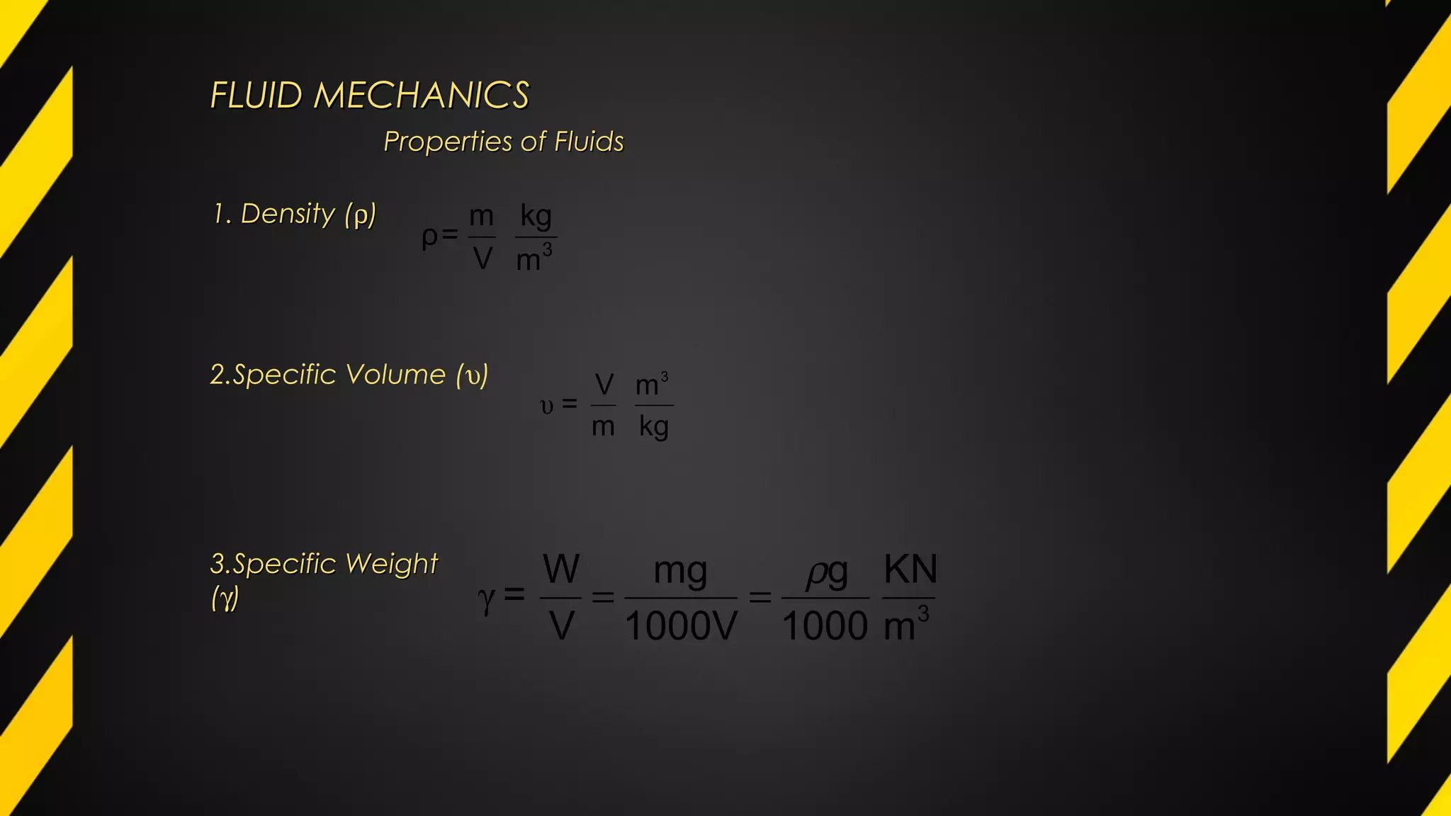
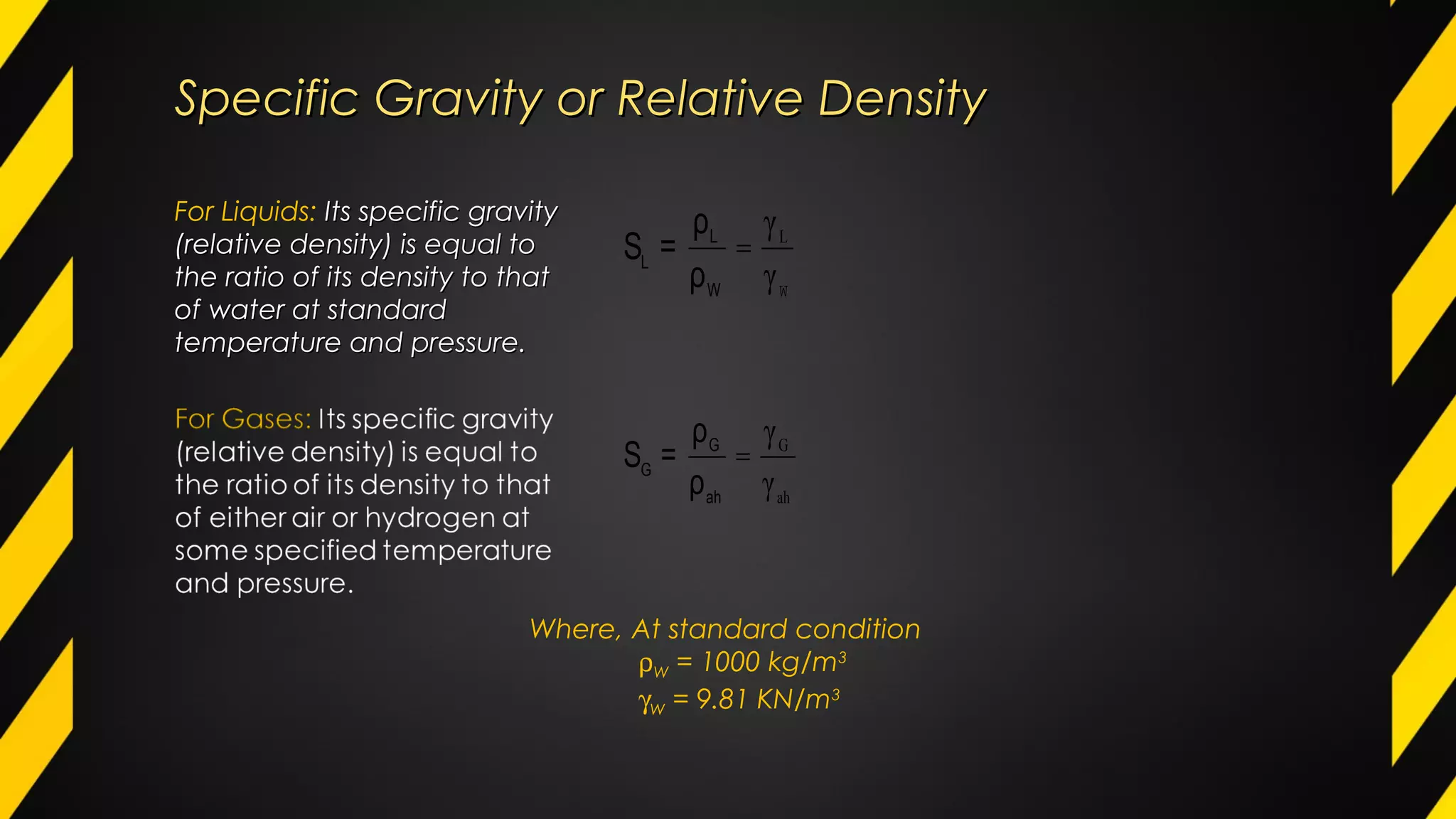
Density, specific volume, specific weight, and specific gravity are discussed along with formulas.
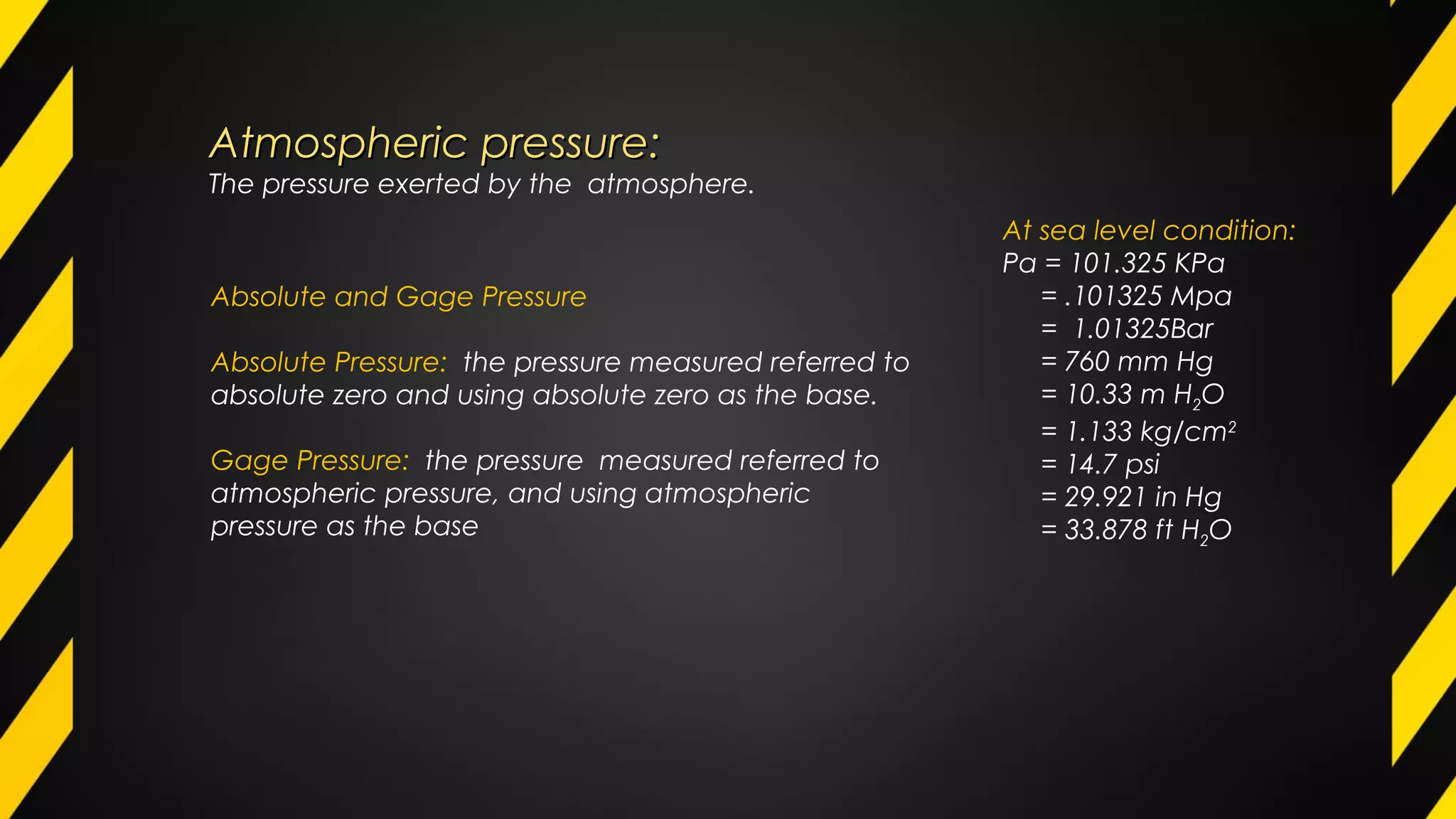
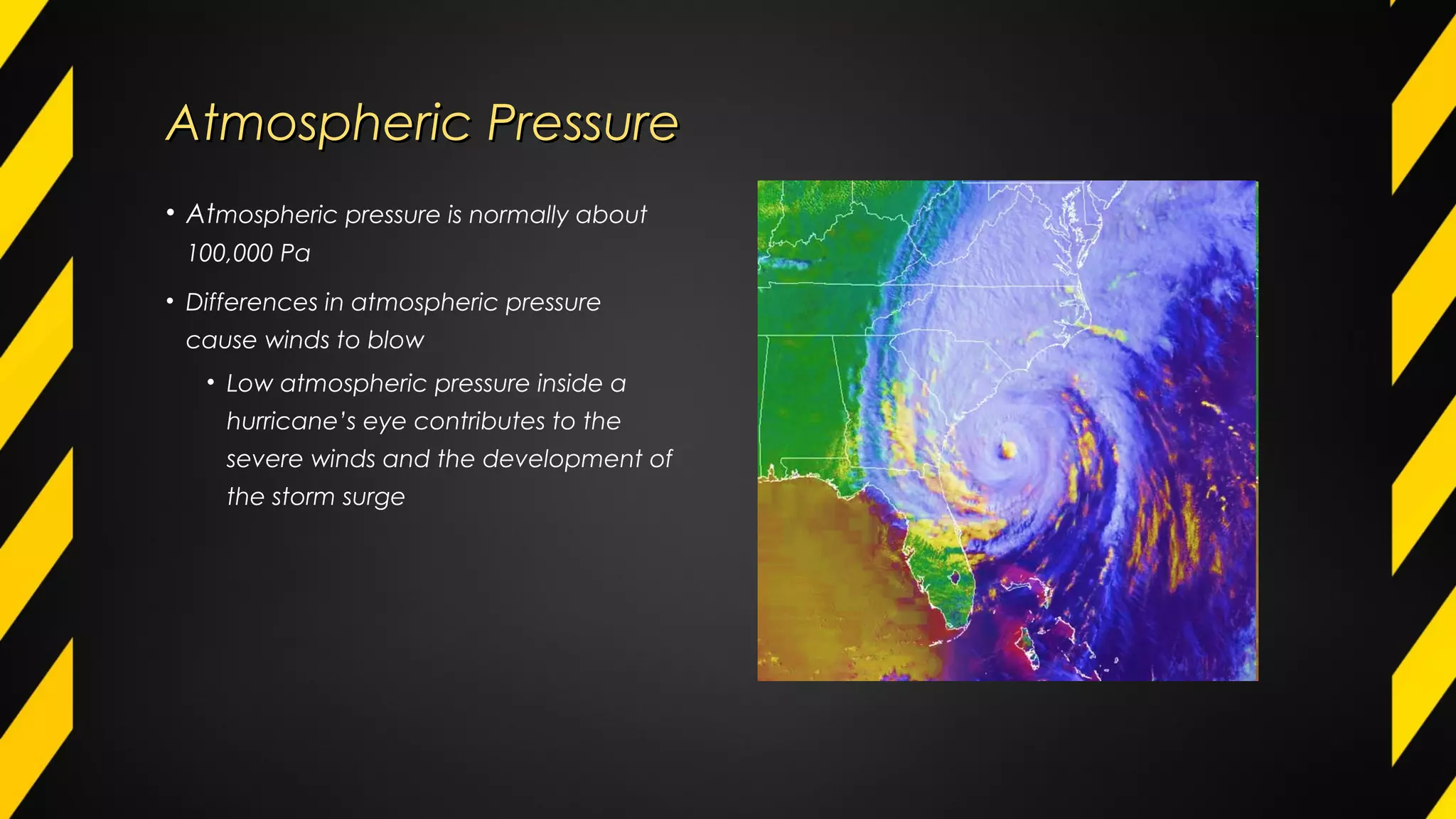
Atmospheric pressure and its impact, along with absolute and gauge pressure definitions.
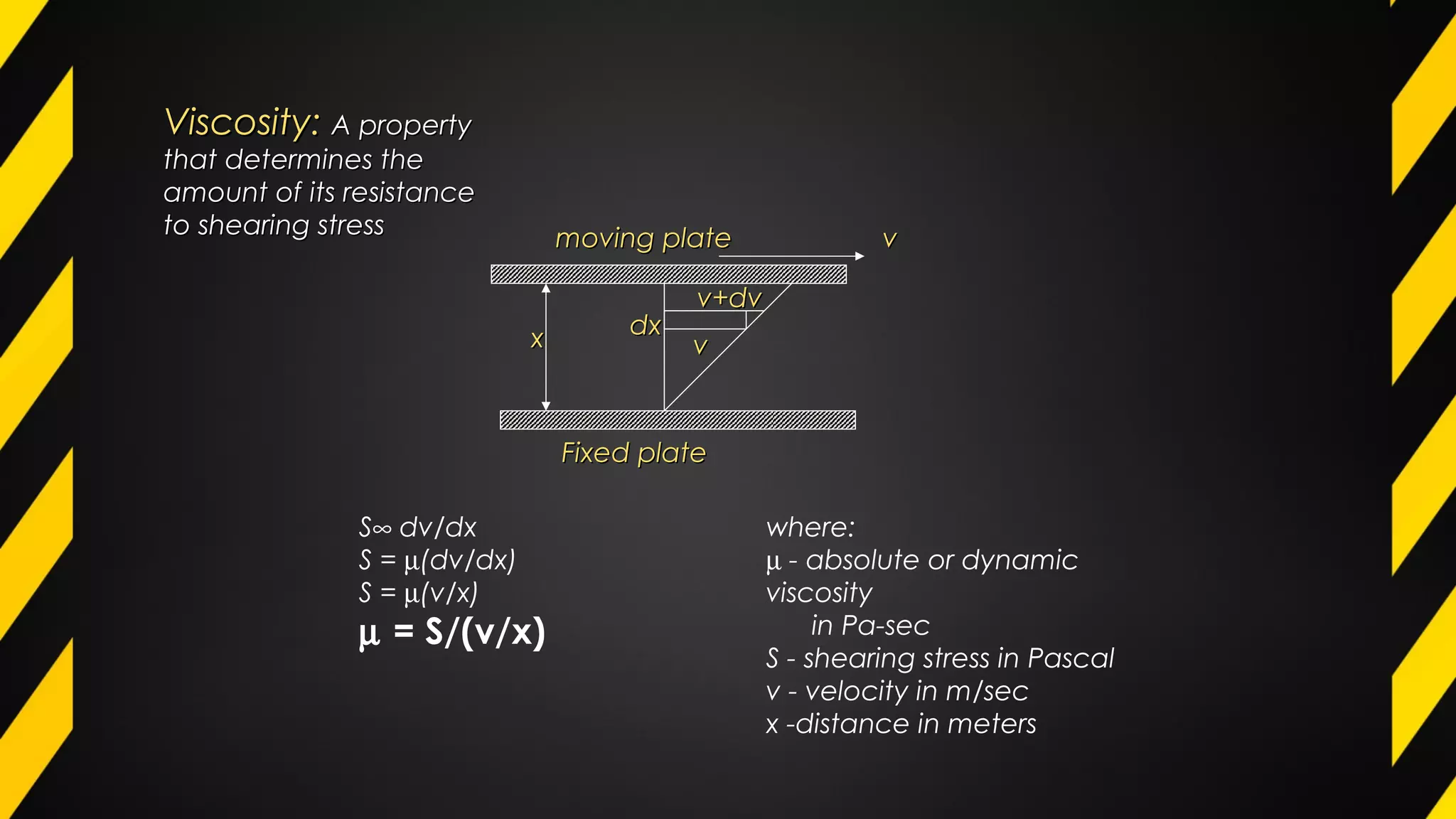
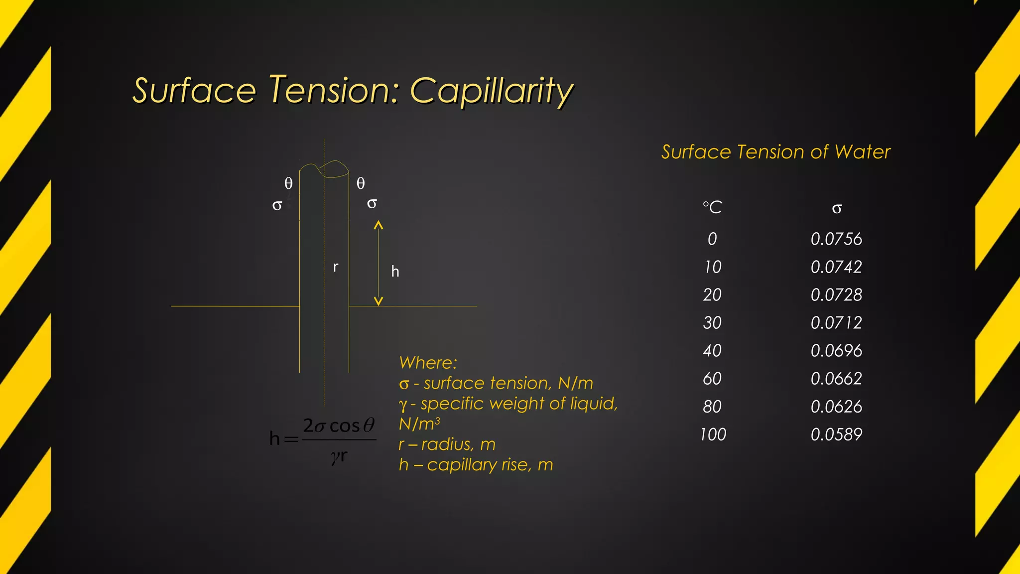
Viscosity as a resistance factor in fluids and surface tension properties, including water tension data.
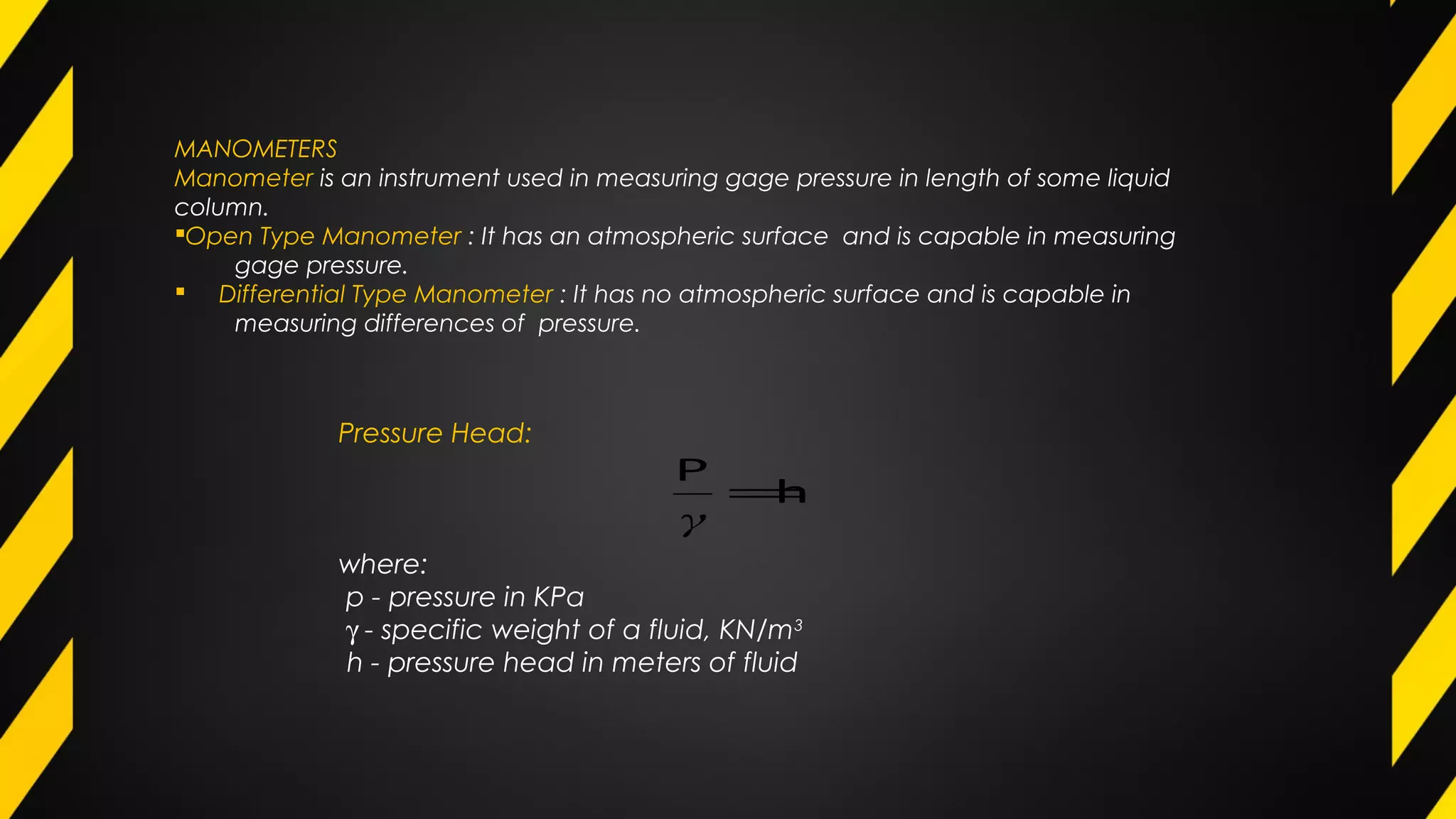
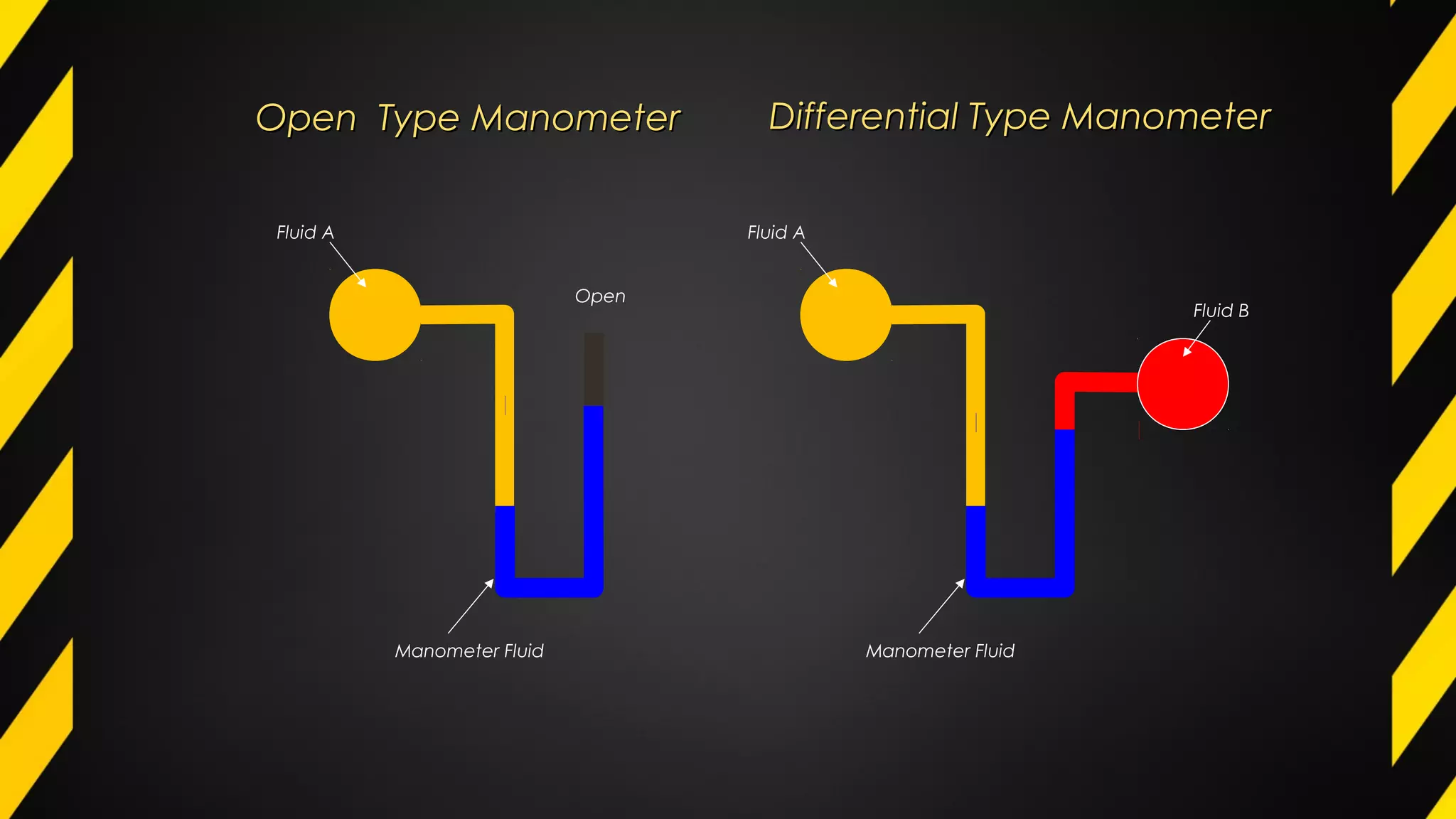
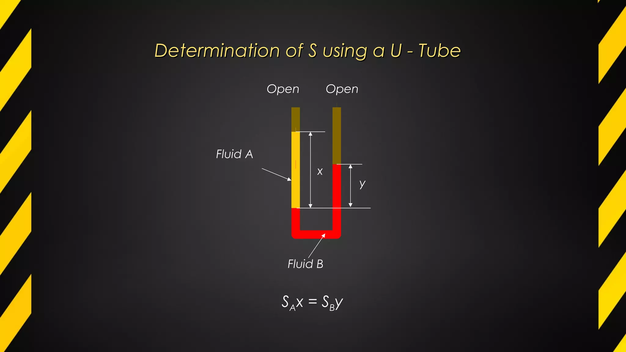
Manometers' types (open and differential) are explained, along with pressure measurement concepts.
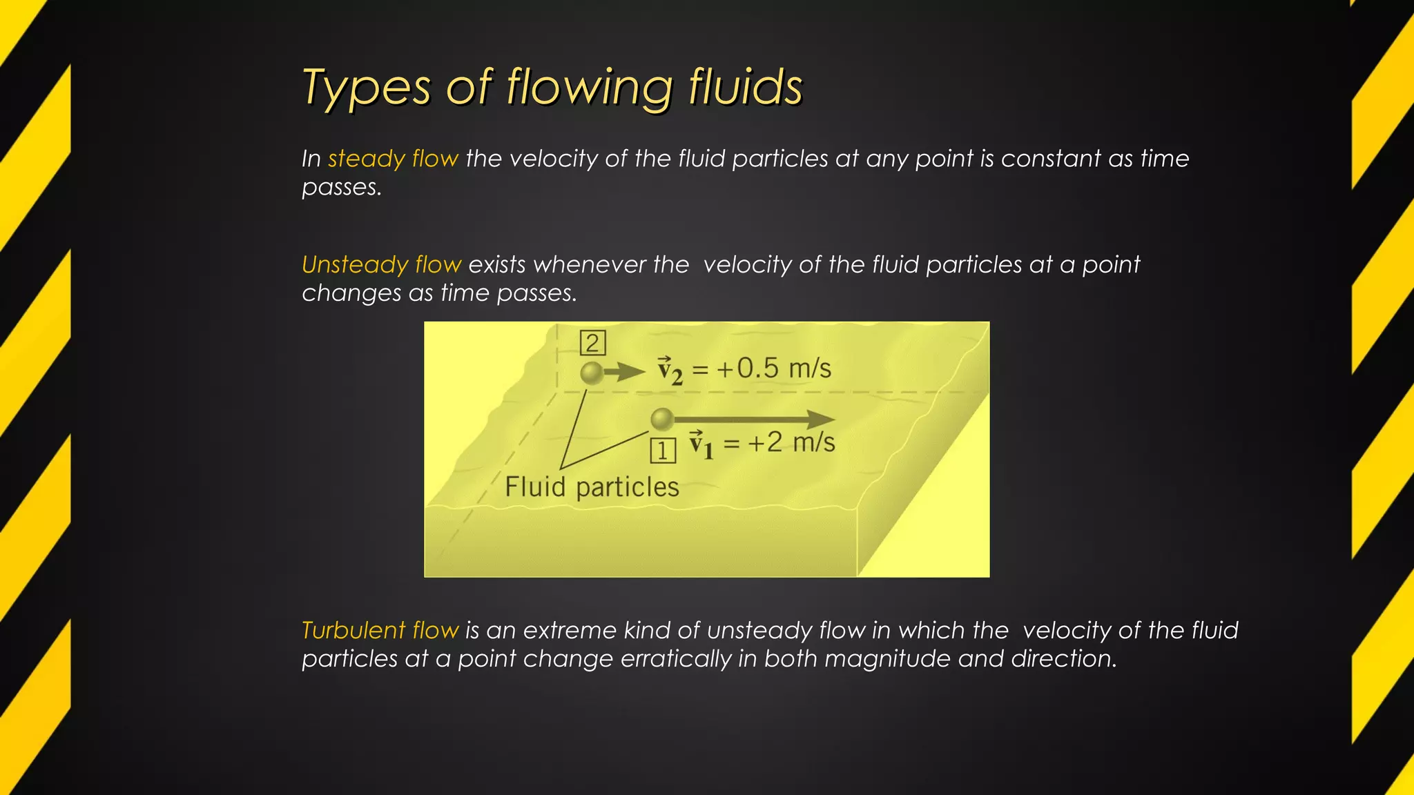
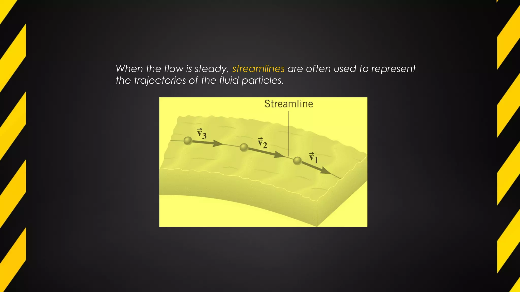
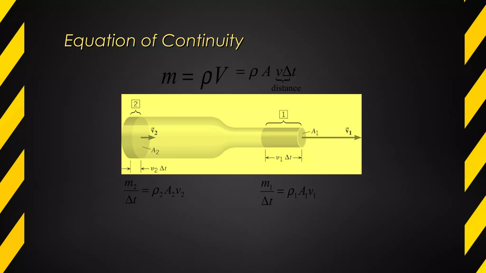
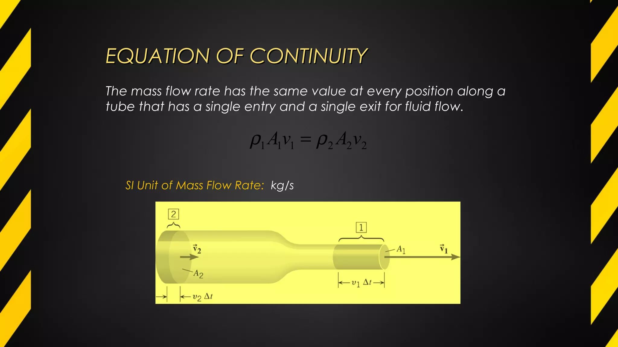
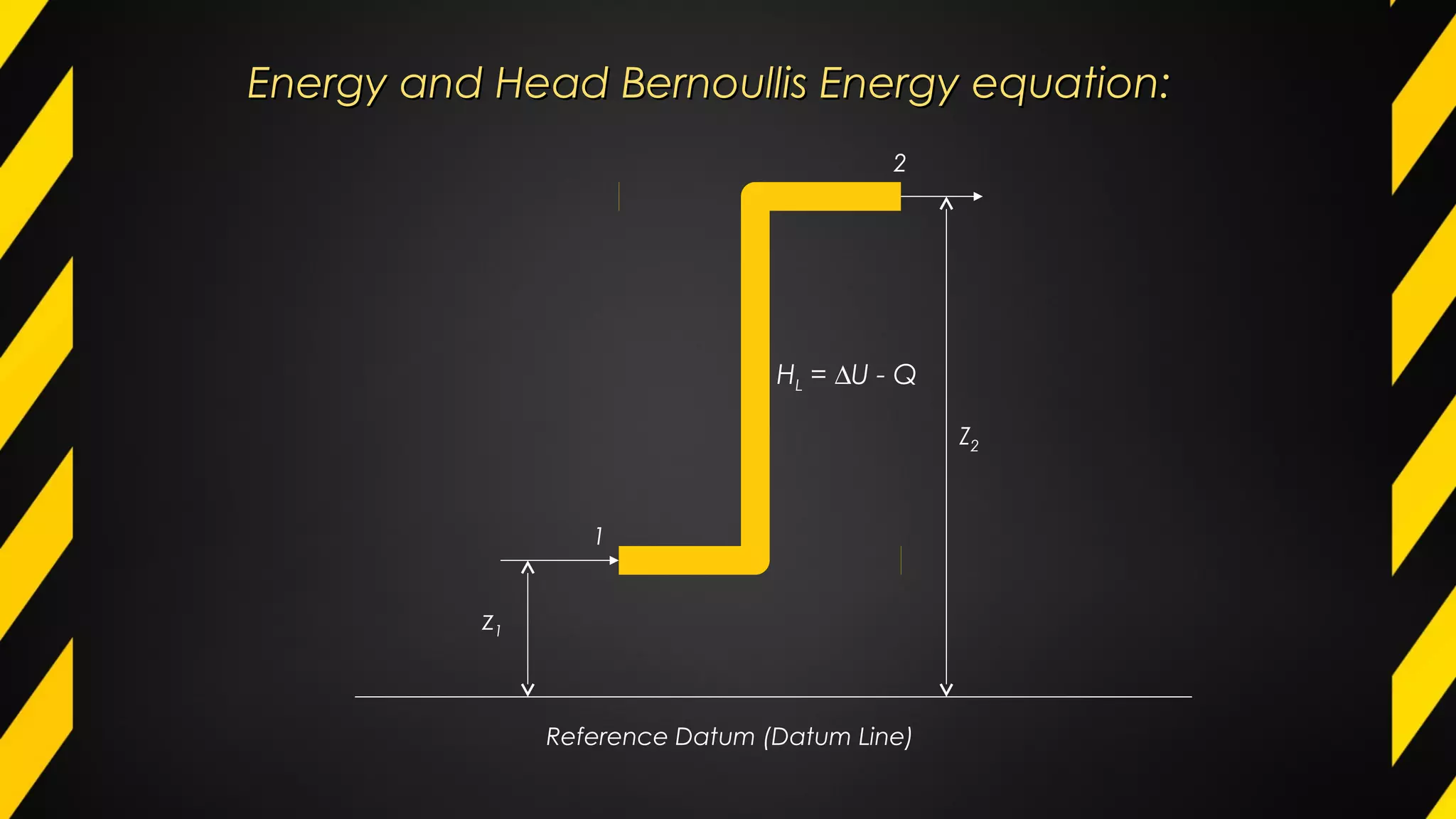
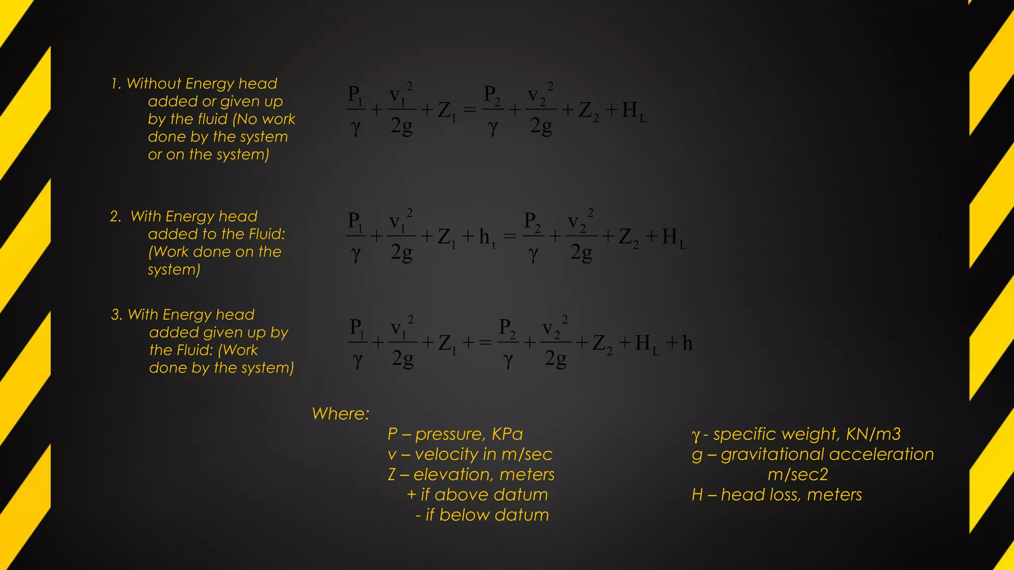
Bernoulli's energy equation relates pressure, elevation, and fluid speed in steady flow scenarios.
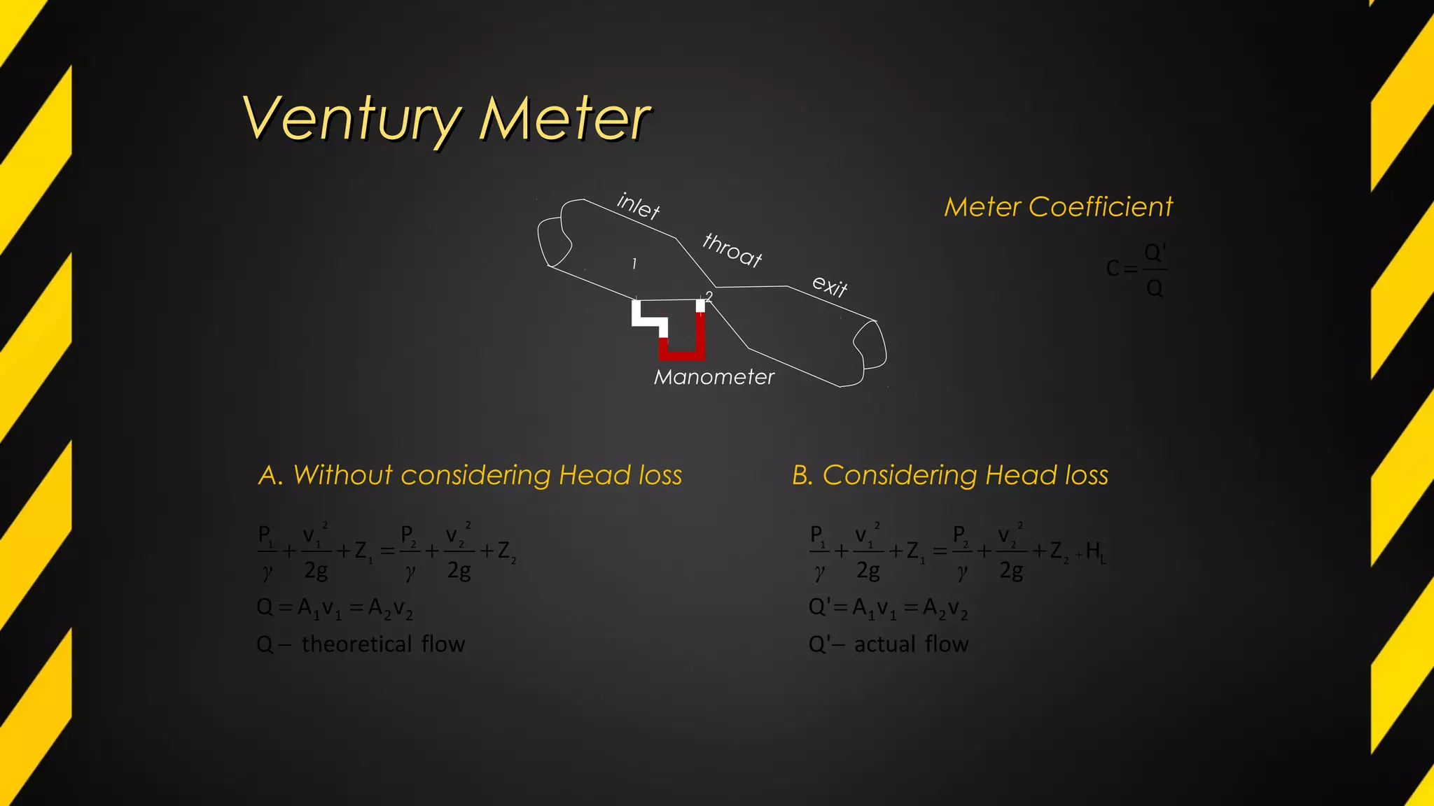
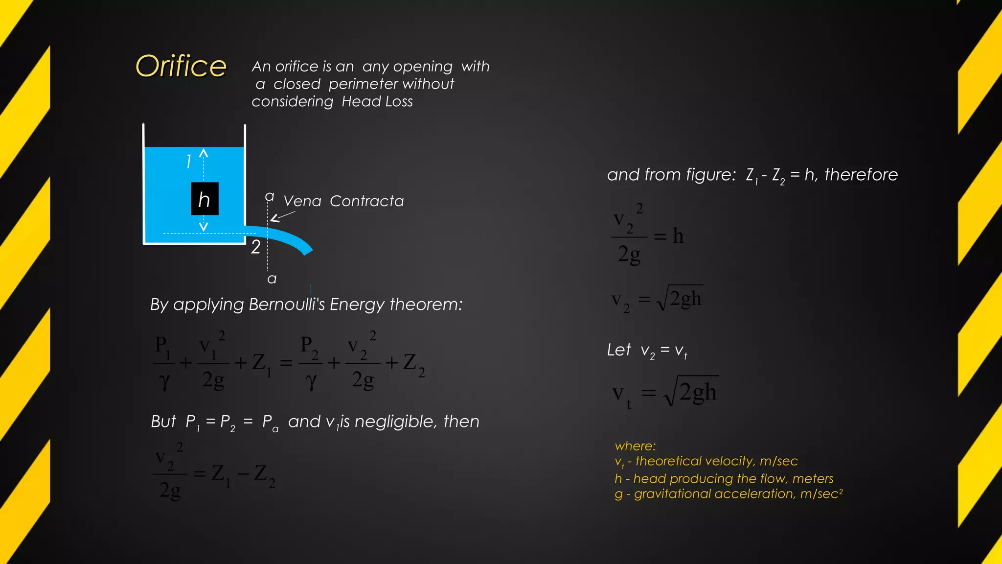
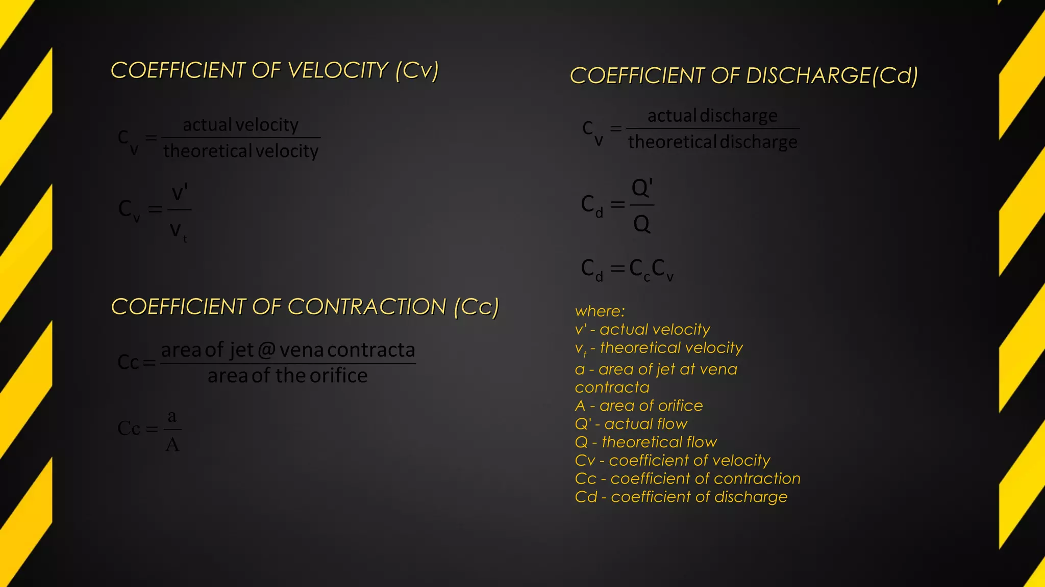
Venturi meter and orifice flow measurement principles, including coefficients of velocity and discharge.
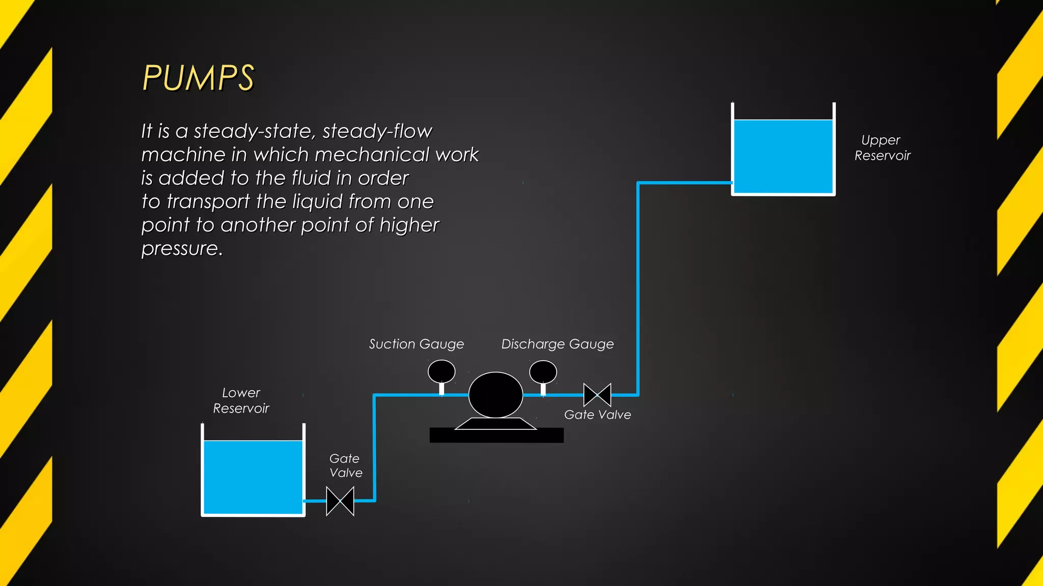
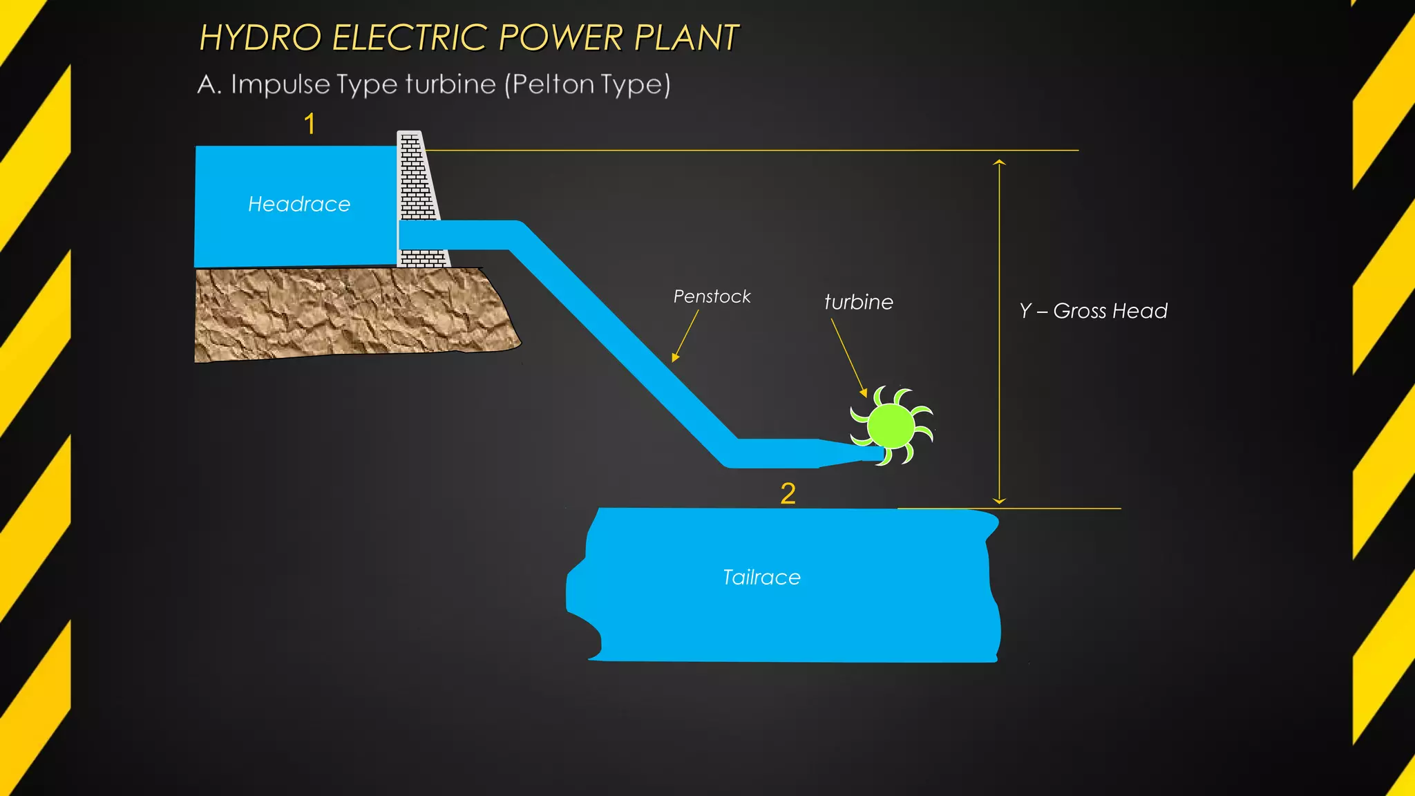
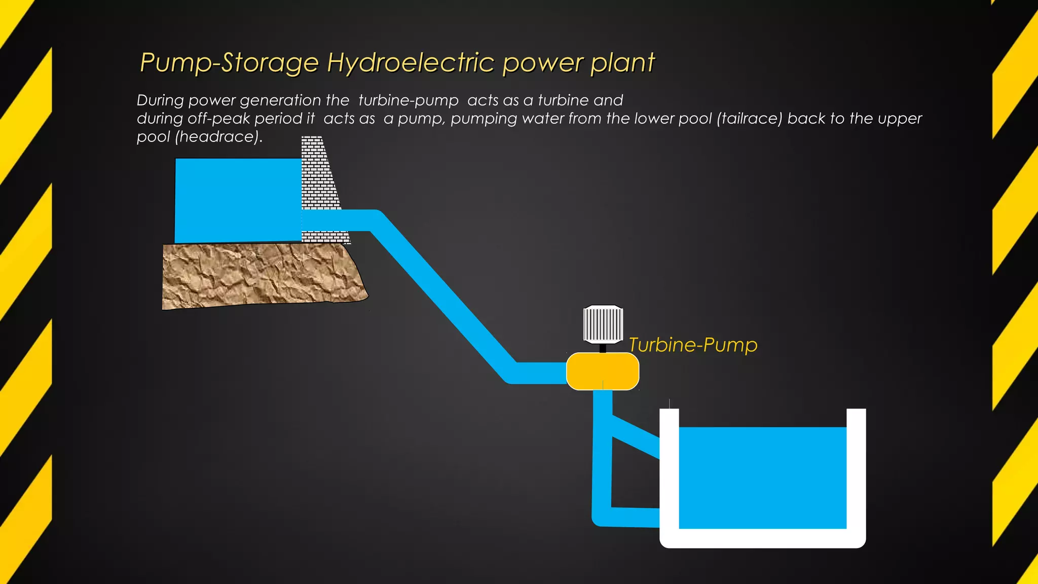
Pumps' functions in fluid transport and power generation in hydroelectric systems are discussed.
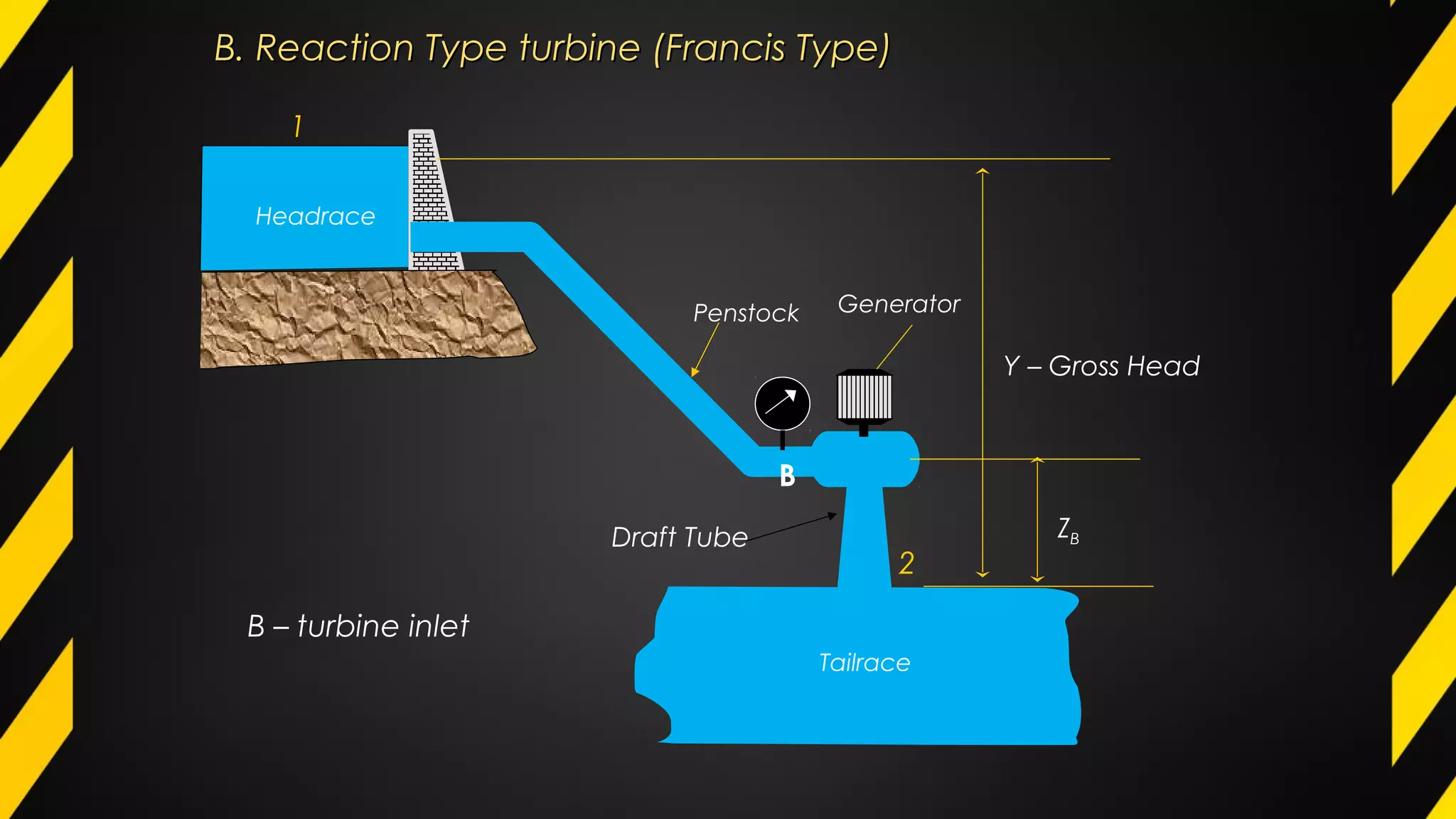
Reaction-type (Francis type) turbine operations and dual uses in pump-storage systems.
Conclusion slide for the presentation, marking the end of the discussion.


