The document discusses key concepts in fluid mechanics including:
1. Pressure is defined as force per unit area and its units are Pascal (SI) or dynes/cm2 (CGS). Atmospheric pressure at sea level is 101,325 Pa.
2. Density is defined as mass per unit volume and has units of kg/m3 (SI) or g/cc (CGS). Specific weight is weight per unit volume and specific gravity is the ratio of a fluid's density to that of water.
3. Viscosity describes a fluid's resistance to flow and is measured by dynamic viscosity in N·s/m2 or kinematic viscosity in m2/s.
![MECHANICAL ENGINEERING – FLUIDMECHANICS
2
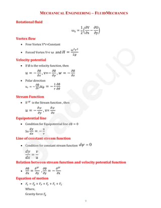
Pressure (P):
• If F be the normal force acting on a surface of area A in contact with liquid,then
pressure exerted by liquid on this surface is: P =F / A
• Units : N /m2 or Pascal (S.I.) and Dyne/cm2 (C.G.S.)
• Dimension
:
[P] =
[F]
[A]
=
[MLT 2 ]
[L2 ]
=[ML-1T -2
]
• Atmospheric pressure:Its value on the surface of the earth at sea level is nearly
1.01*10 5N/ m2 or Pascal in S.I. other practical units of pressure are atmosphere,
bar and torr (mm of Hg)
• 1atm = 1.01 *10 5Pa = 1.01bar = 760 torr
• Fluid Pressure at aPoint:
Density ( ρ):
dp=
dF
dA
• In a fluid, at a point, density ρ is defined as: Mass/volume
• In case of homogenous isotropic substance, it has no directional properties, so is
a scalar.
• It has dimensions [ML-3] and S.I. unit kg/m3 while C.G.S. unit g/ccwith
1g / cc = 10 3kg / m 3
• Density of body = Density of substance
• Relative density or specific gravity which is defined
as:
RD
Densit
Density
of body
of water
Specific Weight ( w):
• It is defined as the weight per unit volume.
• Specific weight =
Weight
=
m.g
Volume Volume
Specific Gravity or Relative Density(s):
• It is the ratio of specific weight of fluid to the specific weight of a standard fluid.
Standard fluid is water in case of liquid and H2 or air in case of gas.
Specific gravity=
𝐷𝑒𝑛𝑠𝑖𝑡𝑦 𝑜𝑓 𝐹𝑙𝑢𝑖𝑑
𝐷𝑒𝑛𝑠𝑖𝑡𝑦 𝑜𝑓 𝑠𝑡𝑎𝑛𝑑𝑎𝑟𝑑 𝐹𝑙𝑢𝑖𝑑
or
𝛾
𝛾𝑤
or
𝜌
𝜌𝑤
Where, 𝛾 Specific weight , and 𝜌
Density of water specific](https://image.slidesharecdn.com/fluidmechanics2-231205112914-eecf6929/85/Fluid-Mechanics-2-pdf-1-320.jpg)


![MECHANICAL ENGINEERING – FLUIDMECHANICS
12
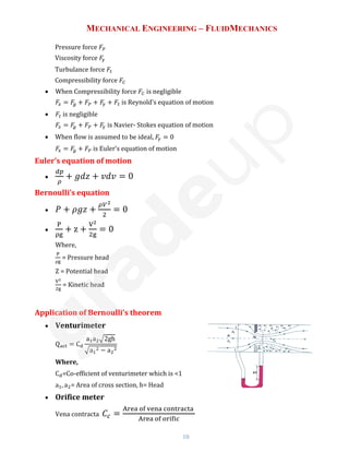
➢ Velocity u =
1
4μ
(−
∂P
∂x
) [R2
− r2]
➢ Shear stress 𝜏 = (−
∂P
∂x
)
r
2
➢ Ratio of maximum to average velocity
Maximum Velocity
Average Velocity
= 2
➢ Drop of pressure in given length
P1 − P2
ρg
= hf =
32u
̅μL
ρgD2
Also called Hagen Poiseuille Equation
Here u
̅=average velocity, P1, P2 = Pressure at two different points in the pipe
• Flow of viscous fluid between two parallel plates
➢ Velocity u =
1
2μ
(−
∂P
∂x
) [ty − y2]
➢ Shear Stress 𝜏 =
1
2
(−
∂P
∂x
) [t − 2y]
➢ Ratio of maximum to average velocity
Maximum Velocity
Average Velocity
=
3
2
➢ Drop of pressure in given length
P1−P2
ρg
= hf =
12u
̅μL
ρgt2
Kinetic energy correction factor
α =
K.E
sec
based on actual velocity
K.E
sec
based on average velocity
For laminar flow α=2 and for turbulent flow α=1.33
Momentum correction factor
β =
Momentum
sec
based on actual velocity
Momentum
sec
based on average velocity
For laminar flow β=1.33 and for turbulent flow β=1.20
Loss of head due to friction in viscous flow
hf =
4flV2
2Dg
Where t is the thickness](https://image.slidesharecdn.com/fluidmechanics2-231205112914-eecf6929/85/Fluid-Mechanics-2-pdf-11-320.jpg)


![MECHANICAL ENGINEERING – FLUIDMECHANICS
20
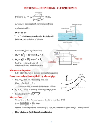
Work done by Pelton turbine
• Work 𝑊 = 𝜌𝑎𝑉1[𝑉𝜔1 − 𝑉𝜔2]𝑢 where 𝑉𝜔1, 𝑉𝜔2are whirl velocity
Hydraulic Efficiency
• Hydraulic Efficiency =
𝟐[𝐕𝛚𝟏±𝐕𝛚𝟐]𝐮
𝐕𝟏
𝟐
• When blade velocity= (inlet velocity of jet)/2 then,
Maximum efficiency
𝟏+𝑪𝒐𝒔∅
𝟐
Degree of reaction
R =
Change of pressure energy inside the runner
Change in total energy
Specific Speed
• For turbine 𝑁𝑠 =
𝑁√𝑃
𝐻
5
4
⁄
where P= power, H= head and N= number of rotation
• Dimensionless Specific speed 𝑁𝑠 =
𝑁√𝑃
(𝑔𝐻)
5
4
⁄
Turbine Specific Speed
(S.I)
Specific Speed
(M.K.S)
Pelton 8.5 to 30 10 to 35
Pelton with two jets 30 to 51 35 to 60
Francis 51 to 255 60 to 300
Kaplan and propeller 255 to 860 300 to 1000
For Pumps, 𝑁𝑠 =
𝑁√𝑄
𝐻
3
4
⁄
where Q is discharge
Unit quantities
• Unit speed (Nu): N = Nu√H
• Unit Power (Pu): P = Pu ∗ H
3
2
⁄
• Unit discharge (Qu): Q = Qu√H
Model laws of turbine
•
𝑄
𝑁𝐷3 = 𝑐𝑜𝑛𝑠𝑡𝑎𝑛𝑡
•
𝑄
√𝐻𝐷2 = 𝑐𝑜𝑛𝑠𝑡𝑎𝑛𝑡](https://image.slidesharecdn.com/fluidmechanics2-231205112914-eecf6929/85/Fluid-Mechanics-2-pdf-19-320.jpg)