SlideShare a Scribd company logo
IJRET: International Journal of Research in Engineering and Technology eISSN: 2319-1163 | pISSN: 2321-7308
_______________________________________________________________________________________
Volume: 04 Issue: 04 | Apr-2015, Available @ http://www.ijret.org 71
FLUE GAS LOW TEMPERATURE HEAT RECOVERY SYSTEM FOR
AIR-CONDITIONING
Nirmal Sajan1
, Ruben Philip2
, Vinayak Suresh3
, Vishnu M4
, Vinay Mathew John5
1
UG Student, Department Of Mechanical Engineering, Saintgits College of Engineering, Kottukulam Hills,
Pathamuttom P. O, Kottayam-686532, Kerala, India
2
UG Student, Department Of Mechanical Engineering, Saintgits College of Engineering, Kottukulam Hills,
Pathamuttom P. O, Kottayam-686532, Kerala, India
3
UG Student, Department Of Mechanical Engineering, Saintgits College of Engineering, Kottukulam Hills,
Pathamuttom P. O, Kottayam-686532, Kerala, India
4
UG Student, Department Of Mechanical Engineering, Saintgits College of Engineering, Kottukulam Hills,
Pathamuttom P. O, Kottayam-686532, Kerala, India
5
Assistant Professor, Department Of Mechanical Engineering, Saintgits College of Engineering, Kottukulam Hills,
Pathamuttom P. O, Kottayam-686532, Kerala, India
Abstract
Huge amount of energy wasted through the flue gas in thermal power station causes great concern in recent years. Discharging
hot flue gas in the environment is not only a wastage of energy but also increases the rate of global warming. Efforts are given
world -wide to harness the energy for useful purposes. In this work, the waste heat of flue gas in a 350 MW thermal power plant is
utilized in vapor absorption air conditioning plant. Gas to liquid multi-pass cross flow heat exchanger that have been placed in
the existing space between boiler and chimney. The dimensions of the finally selected heat exchanger are 0.106m × 2.4m × 3.4m.
The number of pipes required for the heat exchanger is found to be 12 using iteration method and temperature of water at the
outlet of last pipe is 101.1℃. The extracted energy from the flue gas is used to heat water to be utilized in the generator of a vapor
absorption refrigeration system that has produced a refrigerating capacity of 70 TR. approximately. Due to the corrosive nature
of flue gas, heat recovery is confined up to the acid dew point temperature of the flue gas. Suitable software is used to find out the
detailed design parameters of Gas to liquid multi-pass cross flow heat exchangers. Out of many feasible designs of heat
exchangers, the most economic design is selected as the final design.
Keywords—Air Conditioning; Flue Gas; Heat Exchanger; Heat Recovery; Vapour Absorption Machine
--------------------------------------------------------------------***------------------------------------------------------------------
1. INTRODUCTION
Waste heat is heat, which is generated in a process by way of
fuel combustion or chemical reaction, and then dumped into
the environment even though it could still be reused for some
useful and economic purpose. The essential quality of heat is
not the amount but rather its value. The strategy of how to
recover this heat depends in part on the temperature of the
waste heat gases and the economics involved. Large quantity
of hot flue gases is generated from Boilers, Kilns, Ovens and
Furnaces. If some of this waste heat could be recovered, a
considerable amount of primary fuel could be saved. The
energy lost in waste gases cannot be fully recovered.
However, much of the heat could be recovered and loss
minimized by adopting suitable measures.
Depending upon the type of process, waste heat can be
rejected at virtually any temperature from that of chilled
cooling water to high temperature waste gases from an
industrial furnace or kiln. Usually higher the temperature,
higher the quality and more cost effective is the heat
recovery. In any study of waste heat recovery, it is absolutely
necessary that there should be some use for the recovered
heat. Typical examples of use would be preheating of
combustion air, space heating, or pre-heating boiler feed
water or process water. With high temperature heat recovery,
a cascade system of waste heat recovery may be practiced to
ensure that the maximum amount of heat is recovered at the
highest potential. Main objective of this work is to utilize the
waste heat available in exhaust gases coming out of the
Boiler of a thermal power plant. It also intends to use the
waste heat available to run a Vapour Absorption
Refrigeration System which replaces existing Vapour
Compression Refrigeration System which is present in the
administrative block of the plant. This work also aims in
replacing Freon-12 refrigerant which causes ozone depletion
and to reduce the temperature of exhaust gas emitted to the
atmosphere which causes global warming.
2. METHODOLOGY
This work mainly focus only on the heat recovery from the
flue gas in order to run the Li-Br VAM which is having a
cooling capacity of 70 TR. Temperature of the flue gas
available is very low and is about 125°C. Since the
temperature of the flue gas available is very low compared to
other power plants, only single effect VAM can be used for
this air conditioning purpose. Commercially available single
IJRET: International Journal of Research in Engineering and Technology eISSN: 2319-1163 | pISSN: 2321-7308
_______________________________________________________________________________________
Volume: 04 Issue: 04 | Apr-2015, Available @ http://www.ijret.org 72
effect VAM does not require very high temperature and
works on the temperature in the range 80-120℃ and its COP
varies from 0.6 to 0.8. COP of VAM chosen is 0.7.
Fig. 1. Isometric view of the flue gas low temperature heat
recovery system
In order to produce 70 TR, 350 KW of heat is supplied to the
generator of the VAM. So we designed a Multi-pass Gas to
Water heat exchanger to recover waste heat from flue gas to
produce Air conditioning effect. Shape of the heat exchanger
is selected as serpentine and contains 12 pipes each of 10 cm
diameter. The diameter of the pipe is selected based on the
predetermined calculations. Fig. 1. shows the model of the
heat exchanger used for this purpose. The 1:1 model of the
heat exchanger as well as the water flow simulation was done
using Solidworks software. The flow analysis through the
tubes as well as the optimization of the number of the tubes
was done using ANSYS FLUENT software on a 1: 10 model
of the heat exchanger using iteration method. Only a single
pipe is considered for analysis because the dimensions of
each of the pipe as well as the properties of flow through
each of the pipes are the same.
Before finding the outlet water temperature of the heat
exchanger using ANSYS Fluent Software following
assumptions are considered regarding the flow of water
through the heat exchanger and they are,
• Fully developed flow
• Steady flow
• Incompressible flow
• Laminar flow
• There will be perfect mixing of different layers of
water occurring at the bend of pipes in heat
exchanger.
In this iteration method, the input temperature of water
passes to the first pipe of heat exchanger is taken as ambient
temperature of 300 K and its corresponding output
temperature is found out by taking the arithmetic average of
temperatures of different layers at the outlet of the pipe
available using the ANSYS software. At the bend of the first
pipe we assumed that perfect mixing of different layers of
water is occurred so as to get a uniform water temperature.
Then the outlet water temperature of first pipe of heat
exchanger is taken as the input of the second pipe and again
the output temperature of water is found out. This process is
continued until the desired water output temperature is
available at the outlet of the twelfth pipe which is about
374.1 K.
In order to compensate heat losses due to friction due to bend
of pipes and pipe wall, required temperature to be supplied to
generator in the VAM is taken as 400 KW instead of 350
KW which was the calculated value. This Gas to Water
Cross flow Heat Exchanger is to be placed in the space
between boiler and chimney. The hot flue gas coming out
from boiler passes across the cross flow multi pass heat
exchanger and thus heats the water inside the heat exchanger.
This flue gas after passing across the heat exchanger will
goes out of the chimney. The hot water serves as an input to
the Vapour Absorption Machine (VAM) driving Li-Br cycle
to produce the desired air conditioning.
Thermal and structural stress effects need not be considered
at pressures below 15 atm or temperatures below 150°C.Thus
the thermal and structural analysis of the heat exchanger is
not carried out in this work. But these effects are major
considerations above 70 atm or 550°C and seriously limit the
acceptable materials of the heat exchanger. The common
materials used for fabrication of industrial heat exchangers
are aluminum, copper, stainless steel and high carbon steel.
Since this work involves low temperature heat recovery,
stainless steel and high carbon steel are not considered as
they are commonly used in high temperature application and
are very costly. Table 1. shows the comparison of properties
of Aluminum and Copper which are the possible options for
material for the heat exchanger. Since this heat recovery is in
the very low temperature and also aluminum is less denser it
is the most suitable choice.
Table 1. Comparison of Physical Properties of Materials
Material Density
Melting
Point
Boiling
Point
Aluminium 2.70 g·cm−3 660.32 °C 2470 °C
Copper 8.96 g·cm−3 1084.62 °C 2562 °C
The heat exchanger is to be installed in the space between the
boiler and chimney. The region is rectangular in cross section
with a dimension of 1.25m × 7.48m × 17.4m. The
dimensions of the final design of the heat exchanger is
0.106m× 2.4m× 3.4m. The heat exchanger is to be installed
in a similar way as that of the radiator in an automobile i.e.
each tube pass of the heat exchanger intercepts the flow of
the flue gas as it flows from the boiler to the chimney.
3. ANALYTICAL SETUP
The system consists of a water reservoir with makeup feed
arrangement, pump, heat exchanger, vapour absorption
refrigeration system and cooling tower, all of which are
connected by pipes of suitable dimensions. Fig. 2. shows the
detailed sketch of the proposed system. This paper
IJRET: International Journal of Research in Engineering and Technology eISSN: 2319-1163 | pISSN: 2321-7308
_______________________________________________________________________________________
Volume: 04 Issue: 04 | Apr-2015, Available @ http://www.ijret.org 73
encompasses the design and analysis of the heat exchanger
only. The specification of the VAM will be adopted
according to the cooling load requirement of the building
under consideration and the potential of the flue gas available
at the plant. The heat exchanger will be designed to provide
the necessary input to the VAM so as to deliver the desired
air conditioning effect. The specifications of the remaining
part of the system i.e. the reservoir, the pump and the
connecting pipes is to be chosen according to the flow
requirement of the system.
Fig. 2. Detailed sketch of analytical setup
3.1 Working Process
The system is proposed for waste heat recovery in a cascade
process so that the heat recovery process will be efficient.
The working process is intended for maximum heat
recovery from the flue gas which is at a temperature of
125℃, which is a very low temperature compared to that of
most of the thermal power plants. At this very low
temperature the thermal and structural effects on the heat
exchanger to be designed can be neglected. The working
fluid selected is water because of its relative abundance and
its non-toxic nature along with its high heat capacity.
The process begins when the heat exchanger installed in the
space between the boiler and the chimney taps the heat from
the flue gas. The flue gas comes out of two of the
combustion chambers coupled to each of the two gas
turbines installed in the plant. The temperature of the flue
coming out of the turbines are of the order of 550±50℃.
This being a very high temperature is effectively used to
generate steam in a HRSG (Boiler).The generated steam is
then used to run a steam turbine, thus making the power
plant a combined cycle power plant. The temperature of the
flue reduces to almost 125℃ after rejecting heat to the
boiler. This flue is made to flow across a multi - pass cross
flow heat exchanger. The flue gas after rejecting heat to the
heat exchanger passes through the chimney. A pump of
predetermined mass flow rate is used to transfer water from
a reservoir to the heat exchanger which heats up to the
desired temperature through a cascade process involving
multi-pass tubes of the heat exchanger.
The heated water is then pushed forward by the pressure
existing in the system to the generator part of the VAM
which have a capacity of 70 TR and a COP of 0.7. The
water coming out of VAM which is still at a considerable
temperature is brought to ambient temperature by passing it
through the cooling tower which is already present at the
plant. The cooled water is then returned to the reservoir
from where it is again pumped by the water pump. A make-
up feed water arrangement is also provided with the
reservoir to compensate for any losses.
4. DESIGN DATA
The heat exchanger is designed according to the VAM
requirements. So firstly, the amount of heat that is to be
supplied to the generator of the VAM is to be found out. The
available inputs are the capacity of the required system and
its coefficient of performance.
4.1 Heat to be supplied to the Generator of VAM
The heat to be supplied to the generator of VAM can be
found out by the equation,
COP =
QE
QG
(1)
where QG is the heat to be supplied to the generator of
VAM,QE is the heat absorbed in the evaporator and COP is
the coefficient of performance.
4.2 Outlet Temperature of Flue Gas
The outlet temperature of the flue gas is found out using the
equation,
Q = mCp∆T = mCp (Tin – Tout) (2)
where Q is the heat transferred from flue gas to water, m is
the mass flow rate of flue gas, Cp is the specific heat
capacity of flue gas, Tin is the inlet temperature of flue gas
and Tout is the outlet temperature of flue gas.
4.3 Logarithmic Mean Temperature Difference
(LMTD)
The next important step is finding out the LMTD of the heat
exchanger, which is given by
LMTD = ∆Tm =
∆𝑇𝑖− ∆𝑇𝑒
ln
∆𝑇𝑖
∆𝑇𝑒
(3)
where,
∆𝑇𝑖 = Th1 – Tc2 (4)
IJRET: International Journal of Research in Engineering and Technology eISSN: 2319-1163 | pISSN: 2321-7308
_______________________________________________________________________________________
Volume: 04 Issue: 04 | Apr-2015, Available @ http://www.ijret.org 74
∆𝑇𝑒 = Th2 – Tc1 (5)
where Th1 and Th2 are the inlet and outlet temperatures of the
flue gas and Tc1 and Tc2 are the corresponding values of
water.
4.4 Surface Area of the Heat Exchanger
Area of the heat exchanger is found out using the equation,
Heat transfer, Q = UFA∆Tm (6)
where, U is the overall heat transfer coefficient, in W/m2
°C,
A is the surface area of the heat exchanger in m2
and
∆Tm is the LMTD in ℃ and F is the correction factor.
4.5 Mass Flow Rate of Water through Heat
Exchanger
We know that heat transfer,
Q = mCpw ∆T = mCpw (Tout − Tin ) (7)
where, m is the mass flow rate of water in Kg/sec, Q is the
heat transfer in KW, Cpw is the specific heat capacity of
water, Tin is the inlet temperature of water in ℃ and Tout is
the outlet temperature of water in ℃.
4.6 Number of Tubes, Diameter and Length of the
Pipe
For a heat exchanger consisting of n tubes, the total surface
area is given by,
A = πdLn (8)
where, d is the diameter of the tubes, L is the length of a
single tube.
From the above equation the values of d, L, n are optimised
using iteration by taking different values for d, n and L for a
constant surface area and the optimised values are;
d = 10cm
L = 2m
n = 11
4.7 Velocity of Water through the Pipes
It is clear that mass flow rate,
𝑚 = 𝜌𝐴 𝑐 𝑉 (9)
where, ρ is the density of water in Kg/m3
, Ac is the cross
sectional area of heat exchanger, in m2
and V is the velocity
of water through heat exchanger in m/s.
4.8 Energy Savings
Power required for operating VCM =78.2985 KW
Power required for operating VAM = 2% of VCM =1.566
KW
Total Power Saved = 78.2985 – 1.566 = 76.732 KW
Energy saved if air-conditioner works 12 hours per day
= 76.732 × 12 = 920.784 KWhr = 920.784 Units/day.
5. ANALYSIS
The heat exchanger analysis is being carried out using
ANSYS FLUENT software. Although the design involves a
multi-pass heat exchanger consisting of twelve pipes, the
analysis is carried out only on the first and the last pipe of
the heat exchanger. This is because the properties of flue gas
flowing through the space between boiler and chimney and
the water flowing through the pipe respectively are same for
each pipe. The dimensions of the heat exchanger is being
scaled down to one – tenth of its original dimensions due to
considerable difficulty faced during the analysis of 1:1
model of the heat exchanger. But the resulting error will be
only one percent. A rectangular control volume of cross
sectional area of 30 𝑐𝑚2
is also considered which encloses
the pipe. The flow analysis of both the cold fluid and the hot
fluid is being carried out in the control volume considered.
5.1 Velocity Analysis
Since the velocity of flow of flue gas across the heat
exchanger and the velocity of water flowing through each
pipes are the same, only a single pipe including the control
volume is being analysed. The velocity of flow of the flue
gas and water can be theoretically found out using their
known mass flow rates. These can be essentially used as
inputs for software analysis. The solution obtained from the
software is obtained as a streamline simulation.
IJRET: International Journal of Research in Engineering and Technology eISSN: 2319-1163 | pISSN: 2321-7308
_______________________________________________________________________________________
Volume: 04 Issue: 04 | Apr-2015, Available @ http://www.ijret.org 75
Fig. 3. Velocity streamlines of both flue gas and water
Fig. 3. shows the velocity streamlines of both flue gas and
water. From the figure, it can be understood that the velocity
of flue gas increases when it approaches the pipe and
decreases when it passes the pipe. It may be due to, the
reduction in area that occurs when the flue gas approaches
the pipe and the subsequent reduction in pressure. As the
flow area increases the velocity of the flue gas decreases
correspondingly.
Fig. 4. shows the velocity streamline of flue gas only. From
the figure it can be inferred that the velocity of the flue gas
directly below the pipe is almost zero. This may be due to the
near stagnation condition that arises at that region. This is
mainly because of the fact that the particular layer of flue gas
has less chance to escape due to the obstruction created by
the pipe and the continuous collision with fresh flue gas
which nearly impedes its motion. Thus there is less chance of
fresh flue gas interaction with the pipe wall at this region.
Fig. 4. Velocity Streamline of Flue Gas
IJRET: International Journal of Research in Engineering and Technology eISSN: 2319-1163 | pISSN: 2321-7308
_______________________________________________________________________________________
Volume: 04 Issue: 04 | Apr-2015, Available @ http://www.ijret.org 76
Fig. 5. shows the velocity contour plot of water flow at the
outlet of the first pipe. The plot gives the velocity variation in
the radial direction. It can also be inferred from the figure
that the velocity of water layers close to the pipe boundary is
low as compared to the velocity of water layer passing
through the center of the pipe. This is due to the viscous
effects that becomes prominent as the proximity to the pipe
wall increases.
Fig. 5. Velocity contour at the outlet of pipe
The velocity analysis is the basis for all other subsequent
analysis in this work. The variations in velocity is the prime
determinant for the variation of properties like Temperature
and Pressure all across the control volume. It is clear from
the figure that although the velocities of the flue gas and
water involved are small, but they are sufficient enough to
bring a considerable amount of heat transfer in this work.
Many works states that minimizing the pressure drop and the
mass flow rate of the fluids will minimize the operating cost
of the heat exchanger, but it will maximize the size of the
heat exchanger and thus the initial cost. As a rule of thumb,
doubling the mass flow rate will reduce the initial cost by
half but will increase the pumping power requirements by a
factor of roughly eight. Low velocities are helpful in
avoiding erosion, tube vibrations, and noise as well as
pressure drop.
5.2 Temperature Analysis
Temperature analysis is carried out by considering only the
inner wall of the pipes 1 and 12. Other pipes are not
considered. This is because all the pipes exhibit same
behavior.
Fig. 6. Temperature contour of the inner wall of pipe 1
IJRET: International Journal of Research in Engineering and Technology eISSN: 2319-1163 | pISSN: 2321-7308
_______________________________________________________________________________________
Volume: 04 Issue: 04 | Apr-2015, Available @ http://www.ijret.org 77
Fig. 6. shows the temperature contour across inner wall of
pipe 1. From the figure we can see that top surface of pipe 1
shows higher temperature than the bottom surface or any
other surface. It may be due to the vortex flow created by the
flue gas due to the curved shape of the pipes, so that flue gas
molecules from both sides hits the top surface of pipe. This
causes higher temperature of top surface than any other
surface. Temperature of the top surface is almost same as the
flue gas which is at 125℃. It is through the wall of the pipe
heat passes to water inside the pipe.
Fig. 7. shows the temperature contour of inner wall of pipe
12. From this pipe we can see that temperature is same at all
regions of the wall. Water enters the last pipe after passing
through all the 11 pipes and the temperature of water goes on
increasing as it pass through each pipe since it is a multi-pass
heat exchanger. High temperature water at about 95℃ enters
into the last pipe. Since temperature of the water is very high,
heat from the walls is distributed to the walls of the pipe.
Also wall is heated due to temperature of flue gas. This may
be the reason that inner wall of pipe has higher temperature
at all its regions.
Fig. 7. Temperature contour of the inner wall of pipe 12
6. RESULTS AND DISCUSSIONS
6.1 Temperature at Outlet of Each Pipe
The temperature at the outlet of each pipe is taken as an
average value of temperatures at each section considered
along the radial direction. This is because the temperature at
any particular section cannot represent the outlet temperature
correctly. These temperatures are obtained by plotting charts
at each considered section. The average temperatures at the
outlet of each pipes of the heat exchanger are shown in the
Table 2.
The temperature of water entering the first pipe is taken as
ambient temperature, which is 300K. Finally at the end of the
last pipe, the average outlet temperature is almost 374.1K.
The iteration procedure is stopped at the twelfth pipe mainly
due to two reasons. The first reason is that unlike all the other
eleven preceding pipes the temperature rise in the twelfth
pipe is a mere 2℃ compared to five in all the other tubes,
thus it is useless continuing the iteration procedure any
further. The second reason is that the outlet temperature of
the twelfth pipe is almost 374.1 K which vaporises a small
quantity of water to steam which is undesirable. This value is
different from the theoretical outlet temperature of water
(363K). Thus along with maximum possible heat transfer,
this design also provides a factor of safety for the design.
Table 2. Average outlet temperatures of different pipes.
Pipe
No.
Inlet
Temperature
(K)
Outlet
Temperature
(K)
1 300 309.6
2 309.6 320.3
3 320.3 325.1
4 325.1 333.6
5 333.6 341.4
6 341.4 347.7
7 347.7 353.6
8 353.6 359.1
9 359.1 363.6
10 363.6 368
11 368 371.5
12 371.5 374.1
IJRET: International Journal of Research in Engineering and Technology eISSN: 2319-1163 | pISSN: 2321-7308
_______________________________________________________________________________________
Volume: 04 Issue: 04 | Apr-2015, Available @ http://www.ijret.org 78
6.2 Temperature vs. Radial Distance (pipe 1)
Fig. 8. Temperature variation along the radial direction at the
outlet of pipe 1
The graph of Temperature vs. Radial distance at the outlet of
the first pipe is shown in the Fig. 8. This chart gives an idea
about the variation of temperature with radial distance above
and below the axis of the pipe. From the graph it is clear that
temperature is maximum at the top and bottom of the pipe
and there will be almost no change in the temperature along
the centre portion of the pipe (+3.5 to -3.5 cm). This may be
due to the fact that the flue gas transfers its heat to the walls
of the pipes and the water layer that is nearer to the boundary
stays there long due to viscous effects as compared to the
fluid layers at the centre and gets heated up. The velocity of
the fluid layer at the center will be more thus there is less
chance for heat transfer between the different layers of fluid
in that region. Temperature of water layer close to the top
boundary is more as compared to that of bottom layer. This
may be due to the reason cited earlier i.e. the stagnation
condition existing below the heat exchanger pipe. Thus the
stagnant layer of flue gas prevents the transfer of heat by
fresh flue gas. But the top surface will always face a fresh
flue gas flow (Vortex flow) thus increasing the boundary
temperature there.
6.3 Temperature vs. Longitudinal Distance
Fig. 9. Temperature variation along the length of pipe 1 close
to the pipe wall
The temperature vs. longitudinal distance curve for the first
pipe at a section close to the pipe wall region is shown in the
Fig. 9. It shows the variation of temperature along the length
of the tube. Only a single section is considered for analysis
because the charts considered along different sections along
the length have same trends. From the graph it is clear that,
the temperature is not uniform throughout the length of the
pipe. Both increase and decrease in the temperature can be
seen from the chart. This may be due to the temperature
gradient existing between different layers of the fluid. As a
result there will be density gradient at different layers of the
fluid. This causes random movement of fluid molecules thus
distributing temperatures unevenly.
6.4 Temperature vs. Radial Distance (pipe 12)
The graph showing Temperature vs. Radial distance for the
last pipe is shown in the Fig. 10. It can be easily noticed that
the pattern of the curve is very much similar to the curve
shown in figure 8. Only difference is that the temperature at
the top and bottom layer are comparable in this case .This
may be due to the high temperature of water entering the
twelfth pipe unlike the first pipe. All the other pipes will be
showing similar trends like that of Fig. 8 and Fig. 9, except
that there operating temperature will be different.
IJRET: International Journal of Research in Engineering and Technology eISSN: 2319-1163 | pISSN: 2321-7308
_______________________________________________________________________________________
Volume: 04 Issue: 04 | Apr-2015, Available @ http://www.ijret.org 79
Fig. 10. Temperature variation along the radial direction at
the outlet of pipe 12
7. CONCLUSION
As the energy demand in our day to day life escalates
significantly, there are plenty of energies are shuffled in the
universe. Energies are put in an order of low grade and high
grade energies. The regeneration of low grade energy into
some beneficial work is a fantastic job. One such low grade
energy is heat energy. So it is imperative that a significant
and concrete effort should be taken for using heat energy
through waste heat recovery. This work focuses on tapping
the unused heat energy from flue gas and using the same for
day-to-day applications, in this case for air conditioning
application. The main conclusion that can be drawn from
this work is the relative advantage that a VAM has over the
VCM. The dimensions of the final design of the heat
exchanger was obtained as 0.106 m × 2.4 m × 3.4 m. The
finally optimized total number of pipes was 12 and it was
found that further increase in the number of pipes is not
justifiable because the rise in water temperature per pipe is
not above 1℃.The optimized total length and pipe diameter
of the heat exchanger was obtained as 30 m and 0.1 m
respectively. The required mass flow rate of water through
the heat exchanger is 1.516 kg/sec and the average outlet
temperature of last pipe is 101.1 ℃. The temperature of
water exiting the heat exchanger is potential enough to run a
single effect Vapour Absorption Machine. The final
proposed Vapour Absorption Machine effectively replaces
the exiting Vapour Compression Machine.
REFERENCES
[1] K. Balaji and R. Senthil Kumar, “Study of Vapour
Absorption System Using Waste Heat in Sugar
Industry,” IOSR Journal of Engineering (IOSRJEN),
Volume 2, Issue 8, pp. 34-39, 2012.
[2] Ramesh K. Shah and Dusan P. Sekulic,
Fundamentals of Heat Exchanger Design, John
Wiley & Sons, Inc., 1st
Edn., Hoboken, New
Jersey,2003.
[3] Kuppan Thulukkanam, Heat Exchanger Design
Handbook, CRC Press, 2nd
Edn., Boca Raton, 2013.
[4] R. K. Rajput, Heat and Mass Transfer, S. Chand, 5th
Edn., New Delhi, 2014.
[5] R. S. Khurmi and J.K. Gupta, A Textbook of
Refrigeration and Air Conditioning, S. Chand, 5th
Edn., New Delhi, 2014.

More Related Content

What's hot

ME8595 – THERMAL ENGINEERING - II
ME8595 – THERMAL ENGINEERING - IIME8595 – THERMAL ENGINEERING - II
ME8595 – THERMAL ENGINEERING - II
prakash0712
 
Thermal Engineering - II
Thermal Engineering - IIThermal Engineering - II
Thermal Engineering - II
GOBINATHS18
 
Academic project report
Academic project reportAcademic project report
Academic project reportravi wankhede
 
Feedwater heater control: Level
Feedwater heater control: LevelFeedwater heater control: Level
Feedwater heater control: Level
Shari Worthington
 
Waste Heat Recovery Project
Waste Heat Recovery ProjectWaste Heat Recovery Project
Waste Heat Recovery ProjectSUMIT JINDAL
 
Project Abstract- Waste Heat Recovery from IC Enginer Exhaust
Project Abstract- Waste Heat Recovery from IC Enginer ExhaustProject Abstract- Waste Heat Recovery from IC Enginer Exhaust
Project Abstract- Waste Heat Recovery from IC Enginer ExhaustAniruddha Bv
 
Fossil Fuel Steam Generator (Thermal Power Plant)
Fossil Fuel Steam Generator (Thermal Power Plant)Fossil Fuel Steam Generator (Thermal Power Plant)
Fossil Fuel Steam Generator (Thermal Power Plant)
Hashim Hasnain Hadi
 
Waste Heat Recovery from refregeration cycle
Waste Heat Recovery from refregeration cycleWaste Heat Recovery from refregeration cycle
Waste Heat Recovery from refregeration cycleMukesh pratap Singh
 
Waste Heat Recovery Vinay Shukla
Waste Heat Recovery  Vinay ShuklaWaste Heat Recovery  Vinay Shukla
Waste Heat Recovery Vinay Shukla
Vinay Shukla
 
IRJET- Water Cooling With LPG as Refrigerant for Restaurants
IRJET- Water Cooling With LPG as Refrigerant for RestaurantsIRJET- Water Cooling With LPG as Refrigerant for Restaurants
IRJET- Water Cooling With LPG as Refrigerant for Restaurants
IRJET Journal
 
Factors Affecting Boiler Performance
Factors Affecting Boiler PerformanceFactors Affecting Boiler Performance
Factors Affecting Boiler Performance
Manohar Tatwawadi
 
Energy conservation
Energy conservationEnergy conservation
Energy conservation
Qusay Abdulelah
 
Waste Heat Recovery
Waste Heat RecoveryWaste Heat Recovery
Waste Heat Recovery
rajputdanish
 
Boiler Efficiency Improvement through Analysis of Losses
Boiler Efficiency Improvement through Analysis of LossesBoiler Efficiency Improvement through Analysis of Losses
Boiler Efficiency Improvement through Analysis of Losses
ijsrd.com
 
Chapter waste heat recovery p18
Chapter waste heat recovery p18Chapter waste heat recovery p18
Chapter waste heat recovery p18
Nikolay Mavrodiev
 
Improving Efficiency for Boiler and Steam System
Improving Efficiency for Boiler and Steam SystemImproving Efficiency for Boiler and Steam System
Improving Efficiency for Boiler and Steam System
Kamlesh Hariyani
 

What's hot (19)

ME8595 – THERMAL ENGINEERING - II
ME8595 – THERMAL ENGINEERING - IIME8595 – THERMAL ENGINEERING - II
ME8595 – THERMAL ENGINEERING - II
 
Thermal Engineering - II
Thermal Engineering - IIThermal Engineering - II
Thermal Engineering - II
 
Academic project report
Academic project reportAcademic project report
Academic project report
 
Feedwater heater control: Level
Feedwater heater control: LevelFeedwater heater control: Level
Feedwater heater control: Level
 
4 ch1
4 ch14 ch1
4 ch1
 
FINAL PROJECT
FINAL PROJECTFINAL PROJECT
FINAL PROJECT
 
Waste Heat Recovery Project
Waste Heat Recovery ProjectWaste Heat Recovery Project
Waste Heat Recovery Project
 
Project Abstract- Waste Heat Recovery from IC Enginer Exhaust
Project Abstract- Waste Heat Recovery from IC Enginer ExhaustProject Abstract- Waste Heat Recovery from IC Enginer Exhaust
Project Abstract- Waste Heat Recovery from IC Enginer Exhaust
 
4.1 boiler
4.1 boiler4.1 boiler
4.1 boiler
 
Fossil Fuel Steam Generator (Thermal Power Plant)
Fossil Fuel Steam Generator (Thermal Power Plant)Fossil Fuel Steam Generator (Thermal Power Plant)
Fossil Fuel Steam Generator (Thermal Power Plant)
 
Waste Heat Recovery from refregeration cycle
Waste Heat Recovery from refregeration cycleWaste Heat Recovery from refregeration cycle
Waste Heat Recovery from refregeration cycle
 
Waste Heat Recovery Vinay Shukla
Waste Heat Recovery  Vinay ShuklaWaste Heat Recovery  Vinay Shukla
Waste Heat Recovery Vinay Shukla
 
IRJET- Water Cooling With LPG as Refrigerant for Restaurants
IRJET- Water Cooling With LPG as Refrigerant for RestaurantsIRJET- Water Cooling With LPG as Refrigerant for Restaurants
IRJET- Water Cooling With LPG as Refrigerant for Restaurants
 
Factors Affecting Boiler Performance
Factors Affecting Boiler PerformanceFactors Affecting Boiler Performance
Factors Affecting Boiler Performance
 
Energy conservation
Energy conservationEnergy conservation
Energy conservation
 
Waste Heat Recovery
Waste Heat RecoveryWaste Heat Recovery
Waste Heat Recovery
 
Boiler Efficiency Improvement through Analysis of Losses
Boiler Efficiency Improvement through Analysis of LossesBoiler Efficiency Improvement through Analysis of Losses
Boiler Efficiency Improvement through Analysis of Losses
 
Chapter waste heat recovery p18
Chapter waste heat recovery p18Chapter waste heat recovery p18
Chapter waste heat recovery p18
 
Improving Efficiency for Boiler and Steam System
Improving Efficiency for Boiler and Steam SystemImproving Efficiency for Boiler and Steam System
Improving Efficiency for Boiler and Steam System
 

Viewers also liked

Air conditioning cum water cooler
Air conditioning cum water coolerAir conditioning cum water cooler
Air conditioning cum water cooler
Kishan Kumar Mondal
 
K11023 rohan patel rac
K11023 rohan patel racK11023 rohan patel rac
K11023 rohan patel rac
Shraddhey Bhandari
 
process design of water chilling plant
process design of water chilling plantprocess design of water chilling plant
process design of water chilling plant
Dinesh Sannepally
 
ECO FRIENDLY AUTOMOBILE AIR-CONDITIONING UTILIZATION EXHAUST GAS WASTE HEAT O...
ECO FRIENDLY AUTOMOBILE AIR-CONDITIONING UTILIZATION EXHAUST GAS WASTE HEAT O...ECO FRIENDLY AUTOMOBILE AIR-CONDITIONING UTILIZATION EXHAUST GAS WASTE HEAT O...
ECO FRIENDLY AUTOMOBILE AIR-CONDITIONING UTILIZATION EXHAUST GAS WASTE HEAT O...
IAEME Publication
 
Hot Water Vapour Absorption Chiller
Hot Water Vapour Absorption ChillerHot Water Vapour Absorption Chiller
Hot Water Vapour Absorption Chiller
NOVATECH Engineering possibilities
 
Single effect vs double effect vam
Single effect vs double effect vamSingle effect vs double effect vam
Single effect vs double effect vam
Thermax India
 
Importance of a hospital hvac system
Importance of a hospital hvac systemImportance of a hospital hvac system
Importance of a hospital hvac system
hillyork1
 
Solar Refrigeration System
Solar Refrigeration SystemSolar Refrigeration System
Solar Refrigeration System
Mohammad Shakil Khan
 
PROJECT REPORT ON PELTIER REFRIGERATOR
PROJECT REPORT ON PELTIER REFRIGERATORPROJECT REPORT ON PELTIER REFRIGERATOR
PROJECT REPORT ON PELTIER REFRIGERATOR
ram143526
 
Air condition requirement in hospitals
Air condition requirement in hospitalsAir condition requirement in hospitals
Air condition requirement in hospitalsHeena Kousar
 
Innovative projects in the refrigeration and Air Conditioning sector
Innovative projects in the refrigeration and Air Conditioning sector Innovative projects in the refrigeration and Air Conditioning sector
Innovative projects in the refrigeration and Air Conditioning sector
UNEP OzonAction
 
SOLAR POWER VAPOUR ABSORPTION REFRIGERATION SYSTEM
SOLAR POWER VAPOUR ABSORPTION REFRIGERATION SYSTEMSOLAR POWER VAPOUR ABSORPTION REFRIGERATION SYSTEM
SOLAR POWER VAPOUR ABSORPTION REFRIGERATION SYSTEM
aj12345ay
 
Water Chilled Airconditioning
Water Chilled AirconditioningWater Chilled Airconditioning
Water Chilled Airconditioning
Aljon Altiche
 
Refrigeration And Air Conditioning
Refrigeration And Air ConditioningRefrigeration And Air Conditioning
Refrigeration And Air ConditioningSaurabh Jain
 
Development of vapour absorption refrigeration system in vehicles
Development of vapour absorption refrigeration system in vehiclesDevelopment of vapour absorption refrigeration system in vehicles
Development of vapour absorption refrigeration system in vehicles
Ashish Singh
 

Viewers also liked (18)

report
reportreport
report
 
cryogas
cryogascryogas
cryogas
 
Air conditioning cum water cooler
Air conditioning cum water coolerAir conditioning cum water cooler
Air conditioning cum water cooler
 
LBARS ABHI
LBARS ABHILBARS ABHI
LBARS ABHI
 
K11023 rohan patel rac
K11023 rohan patel racK11023 rohan patel rac
K11023 rohan patel rac
 
process design of water chilling plant
process design of water chilling plantprocess design of water chilling plant
process design of water chilling plant
 
ECO FRIENDLY AUTOMOBILE AIR-CONDITIONING UTILIZATION EXHAUST GAS WASTE HEAT O...
ECO FRIENDLY AUTOMOBILE AIR-CONDITIONING UTILIZATION EXHAUST GAS WASTE HEAT O...ECO FRIENDLY AUTOMOBILE AIR-CONDITIONING UTILIZATION EXHAUST GAS WASTE HEAT O...
ECO FRIENDLY AUTOMOBILE AIR-CONDITIONING UTILIZATION EXHAUST GAS WASTE HEAT O...
 
Hot Water Vapour Absorption Chiller
Hot Water Vapour Absorption ChillerHot Water Vapour Absorption Chiller
Hot Water Vapour Absorption Chiller
 
Single effect vs double effect vam
Single effect vs double effect vamSingle effect vs double effect vam
Single effect vs double effect vam
 
Importance of a hospital hvac system
Importance of a hospital hvac systemImportance of a hospital hvac system
Importance of a hospital hvac system
 
Solar Refrigeration System
Solar Refrigeration SystemSolar Refrigeration System
Solar Refrigeration System
 
PROJECT REPORT ON PELTIER REFRIGERATOR
PROJECT REPORT ON PELTIER REFRIGERATORPROJECT REPORT ON PELTIER REFRIGERATOR
PROJECT REPORT ON PELTIER REFRIGERATOR
 
Air condition requirement in hospitals
Air condition requirement in hospitalsAir condition requirement in hospitals
Air condition requirement in hospitals
 
Innovative projects in the refrigeration and Air Conditioning sector
Innovative projects in the refrigeration and Air Conditioning sector Innovative projects in the refrigeration and Air Conditioning sector
Innovative projects in the refrigeration and Air Conditioning sector
 
SOLAR POWER VAPOUR ABSORPTION REFRIGERATION SYSTEM
SOLAR POWER VAPOUR ABSORPTION REFRIGERATION SYSTEMSOLAR POWER VAPOUR ABSORPTION REFRIGERATION SYSTEM
SOLAR POWER VAPOUR ABSORPTION REFRIGERATION SYSTEM
 
Water Chilled Airconditioning
Water Chilled AirconditioningWater Chilled Airconditioning
Water Chilled Airconditioning
 
Refrigeration And Air Conditioning
Refrigeration And Air ConditioningRefrigeration And Air Conditioning
Refrigeration And Air Conditioning
 
Development of vapour absorption refrigeration system in vehicles
Development of vapour absorption refrigeration system in vehiclesDevelopment of vapour absorption refrigeration system in vehicles
Development of vapour absorption refrigeration system in vehicles
 

Similar to Flue gas low temperature heat recovery system for air conditioning

Welcome to International Journal of Engineering Research and Development (IJERD)
Welcome to International Journal of Engineering Research and Development (IJERD)Welcome to International Journal of Engineering Research and Development (IJERD)
Welcome to International Journal of Engineering Research and Development (IJERD)
IJERD Editor
 
Experimental Analysis on Thermosyphon Heatpipe to Find Heat Transfer Coefficent
Experimental Analysis on Thermosyphon Heatpipe to Find Heat Transfer CoefficentExperimental Analysis on Thermosyphon Heatpipe to Find Heat Transfer Coefficent
Experimental Analysis on Thermosyphon Heatpipe to Find Heat Transfer Coefficent
IRJET Journal
 
IRJET- Optimization of Flat Plate Solar Collector with Novel Heat Collect...
IRJET-  	  Optimization of Flat Plate Solar Collector with Novel Heat Collect...IRJET-  	  Optimization of Flat Plate Solar Collector with Novel Heat Collect...
IRJET- Optimization of Flat Plate Solar Collector with Novel Heat Collect...
IRJET Journal
 
EXPERIMENTAL INVESTIGATION OF WASTE HEAT RECOVERY SYSTEM FOR DOMESTIC REFRIGE...
EXPERIMENTAL INVESTIGATION OF WASTE HEAT RECOVERY SYSTEM FOR DOMESTIC REFRIGE...EXPERIMENTAL INVESTIGATION OF WASTE HEAT RECOVERY SYSTEM FOR DOMESTIC REFRIGE...
EXPERIMENTAL INVESTIGATION OF WASTE HEAT RECOVERY SYSTEM FOR DOMESTIC REFRIGE...
IAEME Publication
 
28. WASTE HEAT RECOVERY.ppt
28. WASTE HEAT RECOVERY.ppt28. WASTE HEAT RECOVERY.ppt
28. WASTE HEAT RECOVERY.ppt
RENERGISTICS
 
IRJET- Experimental Analysis on Performance of Closed Loop Pulsating Heat Pip...
IRJET- Experimental Analysis on Performance of Closed Loop Pulsating Heat Pip...IRJET- Experimental Analysis on Performance of Closed Loop Pulsating Heat Pip...
IRJET- Experimental Analysis on Performance of Closed Loop Pulsating Heat Pip...
IRJET Journal
 
IRJET- Performance Improvement of PCM Assisted Heat Pipe
IRJET- Performance Improvement of PCM Assisted Heat PipeIRJET- Performance Improvement of PCM Assisted Heat Pipe
IRJET- Performance Improvement of PCM Assisted Heat Pipe
IRJET Journal
 
IRJET-Case Study of Supercritical Boiler Technology
IRJET-Case Study of Supercritical Boiler TechnologyIRJET-Case Study of Supercritical Boiler Technology
IRJET-Case Study of Supercritical Boiler Technology
IRJET Journal
 
WASTE HEAT RECOVERY TO INCREASE BOILER EFFICIENCY USING BAGASSE AS FUEL
WASTE HEAT RECOVERY TO INCREASE BOILER EFFICIENCY USING BAGASSE AS FUEL WASTE HEAT RECOVERY TO INCREASE BOILER EFFICIENCY USING BAGASSE AS FUEL
WASTE HEAT RECOVERY TO INCREASE BOILER EFFICIENCY USING BAGASSE AS FUEL
IAEME Publication
 
Study & Review of Heat Recovery Systems for SO2 Gas Generation Process in Sug...
Study & Review of Heat Recovery Systems for SO2 Gas Generation Process in Sug...Study & Review of Heat Recovery Systems for SO2 Gas Generation Process in Sug...
Study & Review of Heat Recovery Systems for SO2 Gas Generation Process in Sug...
IRJET Journal
 
IJET-V2I6P2
IJET-V2I6P2IJET-V2I6P2
International Journal of Engineering Research and Development (IJERD)
International Journal of Engineering Research and Development (IJERD)International Journal of Engineering Research and Development (IJERD)
International Journal of Engineering Research and Development (IJERD)
IJERD Editor
 
IRJET- Uncertainty Analysis of Flat Plate Oscillating Heat Pipe with Differen...
IRJET- Uncertainty Analysis of Flat Plate Oscillating Heat Pipe with Differen...IRJET- Uncertainty Analysis of Flat Plate Oscillating Heat Pipe with Differen...
IRJET- Uncertainty Analysis of Flat Plate Oscillating Heat Pipe with Differen...
IRJET Journal
 
Thermal power plant
Thermal power plantThermal power plant
Thermal power plant
Rabi Kumar
 
Modification of Generator In Electrolux Refrigerator
Modification of Generator In Electrolux RefrigeratorModification of Generator In Electrolux Refrigerator
Modification of Generator In Electrolux Refrigerator
IRJET Journal
 
D013161520
D013161520D013161520
D013161520
IOSR Journals
 
Aph operation and emergency handling
Aph operation and emergency handlingAph operation and emergency handling
Aph operation and emergency handling
Parag Agrawal
 
"Replacement of vapor compression system of domestic refrigerator by an eject...
"Replacement of vapor compression system of domestic refrigerator by an eject..."Replacement of vapor compression system of domestic refrigerator by an eject...
"Replacement of vapor compression system of domestic refrigerator by an eject...
IRJET Journal
 
Waste heat recovery, co geration and tri-generation
Waste heat recovery, co geration and tri-generationWaste heat recovery, co geration and tri-generation
Waste heat recovery, co geration and tri-generation
Amol Kokare
 

Similar to Flue gas low temperature heat recovery system for air conditioning (20)

Welcome to International Journal of Engineering Research and Development (IJERD)
Welcome to International Journal of Engineering Research and Development (IJERD)Welcome to International Journal of Engineering Research and Development (IJERD)
Welcome to International Journal of Engineering Research and Development (IJERD)
 
Experimental Analysis on Thermosyphon Heatpipe to Find Heat Transfer Coefficent
Experimental Analysis on Thermosyphon Heatpipe to Find Heat Transfer CoefficentExperimental Analysis on Thermosyphon Heatpipe to Find Heat Transfer Coefficent
Experimental Analysis on Thermosyphon Heatpipe to Find Heat Transfer Coefficent
 
IRJET- Optimization of Flat Plate Solar Collector with Novel Heat Collect...
IRJET-  	  Optimization of Flat Plate Solar Collector with Novel Heat Collect...IRJET-  	  Optimization of Flat Plate Solar Collector with Novel Heat Collect...
IRJET- Optimization of Flat Plate Solar Collector with Novel Heat Collect...
 
EXPERIMENTAL INVESTIGATION OF WASTE HEAT RECOVERY SYSTEM FOR DOMESTIC REFRIGE...
EXPERIMENTAL INVESTIGATION OF WASTE HEAT RECOVERY SYSTEM FOR DOMESTIC REFRIGE...EXPERIMENTAL INVESTIGATION OF WASTE HEAT RECOVERY SYSTEM FOR DOMESTIC REFRIGE...
EXPERIMENTAL INVESTIGATION OF WASTE HEAT RECOVERY SYSTEM FOR DOMESTIC REFRIGE...
 
28. WASTE HEAT RECOVERY.ppt
28. WASTE HEAT RECOVERY.ppt28. WASTE HEAT RECOVERY.ppt
28. WASTE HEAT RECOVERY.ppt
 
IRJET- Experimental Analysis on Performance of Closed Loop Pulsating Heat Pip...
IRJET- Experimental Analysis on Performance of Closed Loop Pulsating Heat Pip...IRJET- Experimental Analysis on Performance of Closed Loop Pulsating Heat Pip...
IRJET- Experimental Analysis on Performance of Closed Loop Pulsating Heat Pip...
 
IRJET- Performance Improvement of PCM Assisted Heat Pipe
IRJET- Performance Improvement of PCM Assisted Heat PipeIRJET- Performance Improvement of PCM Assisted Heat Pipe
IRJET- Performance Improvement of PCM Assisted Heat Pipe
 
IRJET-Case Study of Supercritical Boiler Technology
IRJET-Case Study of Supercritical Boiler TechnologyIRJET-Case Study of Supercritical Boiler Technology
IRJET-Case Study of Supercritical Boiler Technology
 
WASTE HEAT RECOVERY TO INCREASE BOILER EFFICIENCY USING BAGASSE AS FUEL
WASTE HEAT RECOVERY TO INCREASE BOILER EFFICIENCY USING BAGASSE AS FUEL WASTE HEAT RECOVERY TO INCREASE BOILER EFFICIENCY USING BAGASSE AS FUEL
WASTE HEAT RECOVERY TO INCREASE BOILER EFFICIENCY USING BAGASSE AS FUEL
 
Study & Review of Heat Recovery Systems for SO2 Gas Generation Process in Sug...
Study & Review of Heat Recovery Systems for SO2 Gas Generation Process in Sug...Study & Review of Heat Recovery Systems for SO2 Gas Generation Process in Sug...
Study & Review of Heat Recovery Systems for SO2 Gas Generation Process in Sug...
 
IJET-V2I6P2
IJET-V2I6P2IJET-V2I6P2
IJET-V2I6P2
 
International Journal of Engineering Research and Development (IJERD)
International Journal of Engineering Research and Development (IJERD)International Journal of Engineering Research and Development (IJERD)
International Journal of Engineering Research and Development (IJERD)
 
IRJET- Uncertainty Analysis of Flat Plate Oscillating Heat Pipe with Differen...
IRJET- Uncertainty Analysis of Flat Plate Oscillating Heat Pipe with Differen...IRJET- Uncertainty Analysis of Flat Plate Oscillating Heat Pipe with Differen...
IRJET- Uncertainty Analysis of Flat Plate Oscillating Heat Pipe with Differen...
 
Thermal power plant
Thermal power plantThermal power plant
Thermal power plant
 
Modification of Generator In Electrolux Refrigerator
Modification of Generator In Electrolux RefrigeratorModification of Generator In Electrolux Refrigerator
Modification of Generator In Electrolux Refrigerator
 
D013161520
D013161520D013161520
D013161520
 
Article - 2012 PTQ Q1
Article - 2012 PTQ Q1Article - 2012 PTQ Q1
Article - 2012 PTQ Q1
 
Aph operation and emergency handling
Aph operation and emergency handlingAph operation and emergency handling
Aph operation and emergency handling
 
"Replacement of vapor compression system of domestic refrigerator by an eject...
"Replacement of vapor compression system of domestic refrigerator by an eject..."Replacement of vapor compression system of domestic refrigerator by an eject...
"Replacement of vapor compression system of domestic refrigerator by an eject...
 
Waste heat recovery, co geration and tri-generation
Waste heat recovery, co geration and tri-generationWaste heat recovery, co geration and tri-generation
Waste heat recovery, co geration and tri-generation
 

More from eSAT Journals

Mechanical properties of hybrid fiber reinforced concrete for pavements
Mechanical properties of hybrid fiber reinforced concrete for pavementsMechanical properties of hybrid fiber reinforced concrete for pavements
Mechanical properties of hybrid fiber reinforced concrete for pavements
eSAT Journals
 
Material management in construction – a case study
Material management in construction – a case studyMaterial management in construction – a case study
Material management in construction – a case study
eSAT Journals
 
Managing drought short term strategies in semi arid regions a case study
Managing drought    short term strategies in semi arid regions  a case studyManaging drought    short term strategies in semi arid regions  a case study
Managing drought short term strategies in semi arid regions a case study
eSAT Journals
 
Life cycle cost analysis of overlay for an urban road in bangalore
Life cycle cost analysis of overlay for an urban road in bangaloreLife cycle cost analysis of overlay for an urban road in bangalore
Life cycle cost analysis of overlay for an urban road in bangalore
eSAT Journals
 
Laboratory studies of dense bituminous mixes ii with reclaimed asphalt materials
Laboratory studies of dense bituminous mixes ii with reclaimed asphalt materialsLaboratory studies of dense bituminous mixes ii with reclaimed asphalt materials
Laboratory studies of dense bituminous mixes ii with reclaimed asphalt materials
eSAT Journals
 
Laboratory investigation of expansive soil stabilized with natural inorganic ...
Laboratory investigation of expansive soil stabilized with natural inorganic ...Laboratory investigation of expansive soil stabilized with natural inorganic ...
Laboratory investigation of expansive soil stabilized with natural inorganic ...
eSAT Journals
 
Influence of reinforcement on the behavior of hollow concrete block masonry p...
Influence of reinforcement on the behavior of hollow concrete block masonry p...Influence of reinforcement on the behavior of hollow concrete block masonry p...
Influence of reinforcement on the behavior of hollow concrete block masonry p...
eSAT Journals
 
Influence of compaction energy on soil stabilized with chemical stabilizer
Influence of compaction energy on soil stabilized with chemical stabilizerInfluence of compaction energy on soil stabilized with chemical stabilizer
Influence of compaction energy on soil stabilized with chemical stabilizer
eSAT Journals
 
Geographical information system (gis) for water resources management
Geographical information system (gis) for water resources managementGeographical information system (gis) for water resources management
Geographical information system (gis) for water resources management
eSAT Journals
 
Forest type mapping of bidar forest division, karnataka using geoinformatics ...
Forest type mapping of bidar forest division, karnataka using geoinformatics ...Forest type mapping of bidar forest division, karnataka using geoinformatics ...
Forest type mapping of bidar forest division, karnataka using geoinformatics ...
eSAT Journals
 
Factors influencing compressive strength of geopolymer concrete
Factors influencing compressive strength of geopolymer concreteFactors influencing compressive strength of geopolymer concrete
Factors influencing compressive strength of geopolymer concrete
eSAT Journals
 
Experimental investigation on circular hollow steel columns in filled with li...
Experimental investigation on circular hollow steel columns in filled with li...Experimental investigation on circular hollow steel columns in filled with li...
Experimental investigation on circular hollow steel columns in filled with li...
eSAT Journals
 
Experimental behavior of circular hsscfrc filled steel tubular columns under ...
Experimental behavior of circular hsscfrc filled steel tubular columns under ...Experimental behavior of circular hsscfrc filled steel tubular columns under ...
Experimental behavior of circular hsscfrc filled steel tubular columns under ...
eSAT Journals
 
Evaluation of punching shear in flat slabs
Evaluation of punching shear in flat slabsEvaluation of punching shear in flat slabs
Evaluation of punching shear in flat slabs
eSAT Journals
 
Evaluation of performance of intake tower dam for recent earthquake in india
Evaluation of performance of intake tower dam for recent earthquake in indiaEvaluation of performance of intake tower dam for recent earthquake in india
Evaluation of performance of intake tower dam for recent earthquake in india
eSAT Journals
 
Evaluation of operational efficiency of urban road network using travel time ...
Evaluation of operational efficiency of urban road network using travel time ...Evaluation of operational efficiency of urban road network using travel time ...
Evaluation of operational efficiency of urban road network using travel time ...
eSAT Journals
 
Estimation of surface runoff in nallur amanikere watershed using scs cn method
Estimation of surface runoff in nallur amanikere watershed using scs cn methodEstimation of surface runoff in nallur amanikere watershed using scs cn method
Estimation of surface runoff in nallur amanikere watershed using scs cn method
eSAT Journals
 
Estimation of morphometric parameters and runoff using rs & gis techniques
Estimation of morphometric parameters and runoff using rs & gis techniquesEstimation of morphometric parameters and runoff using rs & gis techniques
Estimation of morphometric parameters and runoff using rs & gis techniques
eSAT Journals
 
Effect of variation of plastic hinge length on the results of non linear anal...
Effect of variation of plastic hinge length on the results of non linear anal...Effect of variation of plastic hinge length on the results of non linear anal...
Effect of variation of plastic hinge length on the results of non linear anal...
eSAT Journals
 
Effect of use of recycled materials on indirect tensile strength of asphalt c...
Effect of use of recycled materials on indirect tensile strength of asphalt c...Effect of use of recycled materials on indirect tensile strength of asphalt c...
Effect of use of recycled materials on indirect tensile strength of asphalt c...
eSAT Journals
 

More from eSAT Journals (20)

Mechanical properties of hybrid fiber reinforced concrete for pavements
Mechanical properties of hybrid fiber reinforced concrete for pavementsMechanical properties of hybrid fiber reinforced concrete for pavements
Mechanical properties of hybrid fiber reinforced concrete for pavements
 
Material management in construction – a case study
Material management in construction – a case studyMaterial management in construction – a case study
Material management in construction – a case study
 
Managing drought short term strategies in semi arid regions a case study
Managing drought    short term strategies in semi arid regions  a case studyManaging drought    short term strategies in semi arid regions  a case study
Managing drought short term strategies in semi arid regions a case study
 
Life cycle cost analysis of overlay for an urban road in bangalore
Life cycle cost analysis of overlay for an urban road in bangaloreLife cycle cost analysis of overlay for an urban road in bangalore
Life cycle cost analysis of overlay for an urban road in bangalore
 
Laboratory studies of dense bituminous mixes ii with reclaimed asphalt materials
Laboratory studies of dense bituminous mixes ii with reclaimed asphalt materialsLaboratory studies of dense bituminous mixes ii with reclaimed asphalt materials
Laboratory studies of dense bituminous mixes ii with reclaimed asphalt materials
 
Laboratory investigation of expansive soil stabilized with natural inorganic ...
Laboratory investigation of expansive soil stabilized with natural inorganic ...Laboratory investigation of expansive soil stabilized with natural inorganic ...
Laboratory investigation of expansive soil stabilized with natural inorganic ...
 
Influence of reinforcement on the behavior of hollow concrete block masonry p...
Influence of reinforcement on the behavior of hollow concrete block masonry p...Influence of reinforcement on the behavior of hollow concrete block masonry p...
Influence of reinforcement on the behavior of hollow concrete block masonry p...
 
Influence of compaction energy on soil stabilized with chemical stabilizer
Influence of compaction energy on soil stabilized with chemical stabilizerInfluence of compaction energy on soil stabilized with chemical stabilizer
Influence of compaction energy on soil stabilized with chemical stabilizer
 
Geographical information system (gis) for water resources management
Geographical information system (gis) for water resources managementGeographical information system (gis) for water resources management
Geographical information system (gis) for water resources management
 
Forest type mapping of bidar forest division, karnataka using geoinformatics ...
Forest type mapping of bidar forest division, karnataka using geoinformatics ...Forest type mapping of bidar forest division, karnataka using geoinformatics ...
Forest type mapping of bidar forest division, karnataka using geoinformatics ...
 
Factors influencing compressive strength of geopolymer concrete
Factors influencing compressive strength of geopolymer concreteFactors influencing compressive strength of geopolymer concrete
Factors influencing compressive strength of geopolymer concrete
 
Experimental investigation on circular hollow steel columns in filled with li...
Experimental investigation on circular hollow steel columns in filled with li...Experimental investigation on circular hollow steel columns in filled with li...
Experimental investigation on circular hollow steel columns in filled with li...
 
Experimental behavior of circular hsscfrc filled steel tubular columns under ...
Experimental behavior of circular hsscfrc filled steel tubular columns under ...Experimental behavior of circular hsscfrc filled steel tubular columns under ...
Experimental behavior of circular hsscfrc filled steel tubular columns under ...
 
Evaluation of punching shear in flat slabs
Evaluation of punching shear in flat slabsEvaluation of punching shear in flat slabs
Evaluation of punching shear in flat slabs
 
Evaluation of performance of intake tower dam for recent earthquake in india
Evaluation of performance of intake tower dam for recent earthquake in indiaEvaluation of performance of intake tower dam for recent earthquake in india
Evaluation of performance of intake tower dam for recent earthquake in india
 
Evaluation of operational efficiency of urban road network using travel time ...
Evaluation of operational efficiency of urban road network using travel time ...Evaluation of operational efficiency of urban road network using travel time ...
Evaluation of operational efficiency of urban road network using travel time ...
 
Estimation of surface runoff in nallur amanikere watershed using scs cn method
Estimation of surface runoff in nallur amanikere watershed using scs cn methodEstimation of surface runoff in nallur amanikere watershed using scs cn method
Estimation of surface runoff in nallur amanikere watershed using scs cn method
 
Estimation of morphometric parameters and runoff using rs & gis techniques
Estimation of morphometric parameters and runoff using rs & gis techniquesEstimation of morphometric parameters and runoff using rs & gis techniques
Estimation of morphometric parameters and runoff using rs & gis techniques
 
Effect of variation of plastic hinge length on the results of non linear anal...
Effect of variation of plastic hinge length on the results of non linear anal...Effect of variation of plastic hinge length on the results of non linear anal...
Effect of variation of plastic hinge length on the results of non linear anal...
 
Effect of use of recycled materials on indirect tensile strength of asphalt c...
Effect of use of recycled materials on indirect tensile strength of asphalt c...Effect of use of recycled materials on indirect tensile strength of asphalt c...
Effect of use of recycled materials on indirect tensile strength of asphalt c...
 

Recently uploaded

NO1 Uk best vashikaran specialist in delhi vashikaran baba near me online vas...
NO1 Uk best vashikaran specialist in delhi vashikaran baba near me online vas...NO1 Uk best vashikaran specialist in delhi vashikaran baba near me online vas...
NO1 Uk best vashikaran specialist in delhi vashikaran baba near me online vas...
Amil Baba Dawood bangali
 
English lab ppt no titlespecENG PPTt.pdf
English lab ppt no titlespecENG PPTt.pdfEnglish lab ppt no titlespecENG PPTt.pdf
English lab ppt no titlespecENG PPTt.pdf
BrazilAccount1
 
The role of big data in decision making.
The role of big data in decision making.The role of big data in decision making.
The role of big data in decision making.
ankuprajapati0525
 
Architectural Portfolio Sean Lockwood
Architectural Portfolio Sean LockwoodArchitectural Portfolio Sean Lockwood
Architectural Portfolio Sean Lockwood
seandesed
 
ASME IX(9) 2007 Full Version .pdf
ASME IX(9)  2007 Full Version       .pdfASME IX(9)  2007 Full Version       .pdf
ASME IX(9) 2007 Full Version .pdf
AhmedHussein950959
 
H.Seo, ICLR 2024, MLILAB, KAIST AI.pdf
H.Seo,  ICLR 2024, MLILAB,  KAIST AI.pdfH.Seo,  ICLR 2024, MLILAB,  KAIST AI.pdf
H.Seo, ICLR 2024, MLILAB, KAIST AI.pdf
MLILAB
 
ethical hacking-mobile hacking methods.ppt
ethical hacking-mobile hacking methods.pptethical hacking-mobile hacking methods.ppt
ethical hacking-mobile hacking methods.ppt
Jayaprasanna4
 
Investor-Presentation-Q1FY2024 investor presentation document.pptx
Investor-Presentation-Q1FY2024 investor presentation document.pptxInvestor-Presentation-Q1FY2024 investor presentation document.pptx
Investor-Presentation-Q1FY2024 investor presentation document.pptx
AmarGB2
 
Standard Reomte Control Interface - Neometrix
Standard Reomte Control Interface - NeometrixStandard Reomte Control Interface - Neometrix
Standard Reomte Control Interface - Neometrix
Neometrix_Engineering_Pvt_Ltd
 
Planning Of Procurement o different goods and services
Planning Of Procurement o different goods and servicesPlanning Of Procurement o different goods and services
Planning Of Procurement o different goods and services
JoytuBarua2
 
AP LAB PPT.pdf ap lab ppt no title specific
AP LAB PPT.pdf ap lab ppt no title specificAP LAB PPT.pdf ap lab ppt no title specific
AP LAB PPT.pdf ap lab ppt no title specific
BrazilAccount1
 
RAT: Retrieval Augmented Thoughts Elicit Context-Aware Reasoning in Long-Hori...
RAT: Retrieval Augmented Thoughts Elicit Context-Aware Reasoning in Long-Hori...RAT: Retrieval Augmented Thoughts Elicit Context-Aware Reasoning in Long-Hori...
RAT: Retrieval Augmented Thoughts Elicit Context-Aware Reasoning in Long-Hori...
thanhdowork
 
J.Yang, ICLR 2024, MLILAB, KAIST AI.pdf
J.Yang,  ICLR 2024, MLILAB, KAIST AI.pdfJ.Yang,  ICLR 2024, MLILAB, KAIST AI.pdf
J.Yang, ICLR 2024, MLILAB, KAIST AI.pdf
MLILAB
 
Hierarchical Digital Twin of a Naval Power System
Hierarchical Digital Twin of a Naval Power SystemHierarchical Digital Twin of a Naval Power System
Hierarchical Digital Twin of a Naval Power System
Kerry Sado
 
The Benefits and Techniques of Trenchless Pipe Repair.pdf
The Benefits and Techniques of Trenchless Pipe Repair.pdfThe Benefits and Techniques of Trenchless Pipe Repair.pdf
The Benefits and Techniques of Trenchless Pipe Repair.pdf
Pipe Restoration Solutions
 
weather web application report.pdf
weather web application report.pdfweather web application report.pdf
weather web application report.pdf
Pratik Pawar
 
Cosmetic shop management system project report.pdf
Cosmetic shop management system project report.pdfCosmetic shop management system project report.pdf
Cosmetic shop management system project report.pdf
Kamal Acharya
 
Industrial Training at Shahjalal Fertilizer Company Limited (SFCL)
Industrial Training at Shahjalal Fertilizer Company Limited (SFCL)Industrial Training at Shahjalal Fertilizer Company Limited (SFCL)
Industrial Training at Shahjalal Fertilizer Company Limited (SFCL)
MdTanvirMahtab2
 
AKS UNIVERSITY Satna Final Year Project By OM Hardaha.pdf
AKS UNIVERSITY Satna Final Year Project By OM Hardaha.pdfAKS UNIVERSITY Satna Final Year Project By OM Hardaha.pdf
AKS UNIVERSITY Satna Final Year Project By OM Hardaha.pdf
SamSarthak3
 
Immunizing Image Classifiers Against Localized Adversary Attacks
Immunizing Image Classifiers Against Localized Adversary AttacksImmunizing Image Classifiers Against Localized Adversary Attacks
Immunizing Image Classifiers Against Localized Adversary Attacks
gerogepatton
 

Recently uploaded (20)

NO1 Uk best vashikaran specialist in delhi vashikaran baba near me online vas...
NO1 Uk best vashikaran specialist in delhi vashikaran baba near me online vas...NO1 Uk best vashikaran specialist in delhi vashikaran baba near me online vas...
NO1 Uk best vashikaran specialist in delhi vashikaran baba near me online vas...
 
English lab ppt no titlespecENG PPTt.pdf
English lab ppt no titlespecENG PPTt.pdfEnglish lab ppt no titlespecENG PPTt.pdf
English lab ppt no titlespecENG PPTt.pdf
 
The role of big data in decision making.
The role of big data in decision making.The role of big data in decision making.
The role of big data in decision making.
 
Architectural Portfolio Sean Lockwood
Architectural Portfolio Sean LockwoodArchitectural Portfolio Sean Lockwood
Architectural Portfolio Sean Lockwood
 
ASME IX(9) 2007 Full Version .pdf
ASME IX(9)  2007 Full Version       .pdfASME IX(9)  2007 Full Version       .pdf
ASME IX(9) 2007 Full Version .pdf
 
H.Seo, ICLR 2024, MLILAB, KAIST AI.pdf
H.Seo,  ICLR 2024, MLILAB,  KAIST AI.pdfH.Seo,  ICLR 2024, MLILAB,  KAIST AI.pdf
H.Seo, ICLR 2024, MLILAB, KAIST AI.pdf
 
ethical hacking-mobile hacking methods.ppt
ethical hacking-mobile hacking methods.pptethical hacking-mobile hacking methods.ppt
ethical hacking-mobile hacking methods.ppt
 
Investor-Presentation-Q1FY2024 investor presentation document.pptx
Investor-Presentation-Q1FY2024 investor presentation document.pptxInvestor-Presentation-Q1FY2024 investor presentation document.pptx
Investor-Presentation-Q1FY2024 investor presentation document.pptx
 
Standard Reomte Control Interface - Neometrix
Standard Reomte Control Interface - NeometrixStandard Reomte Control Interface - Neometrix
Standard Reomte Control Interface - Neometrix
 
Planning Of Procurement o different goods and services
Planning Of Procurement o different goods and servicesPlanning Of Procurement o different goods and services
Planning Of Procurement o different goods and services
 
AP LAB PPT.pdf ap lab ppt no title specific
AP LAB PPT.pdf ap lab ppt no title specificAP LAB PPT.pdf ap lab ppt no title specific
AP LAB PPT.pdf ap lab ppt no title specific
 
RAT: Retrieval Augmented Thoughts Elicit Context-Aware Reasoning in Long-Hori...
RAT: Retrieval Augmented Thoughts Elicit Context-Aware Reasoning in Long-Hori...RAT: Retrieval Augmented Thoughts Elicit Context-Aware Reasoning in Long-Hori...
RAT: Retrieval Augmented Thoughts Elicit Context-Aware Reasoning in Long-Hori...
 
J.Yang, ICLR 2024, MLILAB, KAIST AI.pdf
J.Yang,  ICLR 2024, MLILAB, KAIST AI.pdfJ.Yang,  ICLR 2024, MLILAB, KAIST AI.pdf
J.Yang, ICLR 2024, MLILAB, KAIST AI.pdf
 
Hierarchical Digital Twin of a Naval Power System
Hierarchical Digital Twin of a Naval Power SystemHierarchical Digital Twin of a Naval Power System
Hierarchical Digital Twin of a Naval Power System
 
The Benefits and Techniques of Trenchless Pipe Repair.pdf
The Benefits and Techniques of Trenchless Pipe Repair.pdfThe Benefits and Techniques of Trenchless Pipe Repair.pdf
The Benefits and Techniques of Trenchless Pipe Repair.pdf
 
weather web application report.pdf
weather web application report.pdfweather web application report.pdf
weather web application report.pdf
 
Cosmetic shop management system project report.pdf
Cosmetic shop management system project report.pdfCosmetic shop management system project report.pdf
Cosmetic shop management system project report.pdf
 
Industrial Training at Shahjalal Fertilizer Company Limited (SFCL)
Industrial Training at Shahjalal Fertilizer Company Limited (SFCL)Industrial Training at Shahjalal Fertilizer Company Limited (SFCL)
Industrial Training at Shahjalal Fertilizer Company Limited (SFCL)
 
AKS UNIVERSITY Satna Final Year Project By OM Hardaha.pdf
AKS UNIVERSITY Satna Final Year Project By OM Hardaha.pdfAKS UNIVERSITY Satna Final Year Project By OM Hardaha.pdf
AKS UNIVERSITY Satna Final Year Project By OM Hardaha.pdf
 
Immunizing Image Classifiers Against Localized Adversary Attacks
Immunizing Image Classifiers Against Localized Adversary AttacksImmunizing Image Classifiers Against Localized Adversary Attacks
Immunizing Image Classifiers Against Localized Adversary Attacks
 

Flue gas low temperature heat recovery system for air conditioning

  • 1. IJRET: International Journal of Research in Engineering and Technology eISSN: 2319-1163 | pISSN: 2321-7308 _______________________________________________________________________________________ Volume: 04 Issue: 04 | Apr-2015, Available @ http://www.ijret.org 71 FLUE GAS LOW TEMPERATURE HEAT RECOVERY SYSTEM FOR AIR-CONDITIONING Nirmal Sajan1 , Ruben Philip2 , Vinayak Suresh3 , Vishnu M4 , Vinay Mathew John5 1 UG Student, Department Of Mechanical Engineering, Saintgits College of Engineering, Kottukulam Hills, Pathamuttom P. O, Kottayam-686532, Kerala, India 2 UG Student, Department Of Mechanical Engineering, Saintgits College of Engineering, Kottukulam Hills, Pathamuttom P. O, Kottayam-686532, Kerala, India 3 UG Student, Department Of Mechanical Engineering, Saintgits College of Engineering, Kottukulam Hills, Pathamuttom P. O, Kottayam-686532, Kerala, India 4 UG Student, Department Of Mechanical Engineering, Saintgits College of Engineering, Kottukulam Hills, Pathamuttom P. O, Kottayam-686532, Kerala, India 5 Assistant Professor, Department Of Mechanical Engineering, Saintgits College of Engineering, Kottukulam Hills, Pathamuttom P. O, Kottayam-686532, Kerala, India Abstract Huge amount of energy wasted through the flue gas in thermal power station causes great concern in recent years. Discharging hot flue gas in the environment is not only a wastage of energy but also increases the rate of global warming. Efforts are given world -wide to harness the energy for useful purposes. In this work, the waste heat of flue gas in a 350 MW thermal power plant is utilized in vapor absorption air conditioning plant. Gas to liquid multi-pass cross flow heat exchanger that have been placed in the existing space between boiler and chimney. The dimensions of the finally selected heat exchanger are 0.106m × 2.4m × 3.4m. The number of pipes required for the heat exchanger is found to be 12 using iteration method and temperature of water at the outlet of last pipe is 101.1℃. The extracted energy from the flue gas is used to heat water to be utilized in the generator of a vapor absorption refrigeration system that has produced a refrigerating capacity of 70 TR. approximately. Due to the corrosive nature of flue gas, heat recovery is confined up to the acid dew point temperature of the flue gas. Suitable software is used to find out the detailed design parameters of Gas to liquid multi-pass cross flow heat exchangers. Out of many feasible designs of heat exchangers, the most economic design is selected as the final design. Keywords—Air Conditioning; Flue Gas; Heat Exchanger; Heat Recovery; Vapour Absorption Machine --------------------------------------------------------------------***------------------------------------------------------------------ 1. INTRODUCTION Waste heat is heat, which is generated in a process by way of fuel combustion or chemical reaction, and then dumped into the environment even though it could still be reused for some useful and economic purpose. The essential quality of heat is not the amount but rather its value. The strategy of how to recover this heat depends in part on the temperature of the waste heat gases and the economics involved. Large quantity of hot flue gases is generated from Boilers, Kilns, Ovens and Furnaces. If some of this waste heat could be recovered, a considerable amount of primary fuel could be saved. The energy lost in waste gases cannot be fully recovered. However, much of the heat could be recovered and loss minimized by adopting suitable measures. Depending upon the type of process, waste heat can be rejected at virtually any temperature from that of chilled cooling water to high temperature waste gases from an industrial furnace or kiln. Usually higher the temperature, higher the quality and more cost effective is the heat recovery. In any study of waste heat recovery, it is absolutely necessary that there should be some use for the recovered heat. Typical examples of use would be preheating of combustion air, space heating, or pre-heating boiler feed water or process water. With high temperature heat recovery, a cascade system of waste heat recovery may be practiced to ensure that the maximum amount of heat is recovered at the highest potential. Main objective of this work is to utilize the waste heat available in exhaust gases coming out of the Boiler of a thermal power plant. It also intends to use the waste heat available to run a Vapour Absorption Refrigeration System which replaces existing Vapour Compression Refrigeration System which is present in the administrative block of the plant. This work also aims in replacing Freon-12 refrigerant which causes ozone depletion and to reduce the temperature of exhaust gas emitted to the atmosphere which causes global warming. 2. METHODOLOGY This work mainly focus only on the heat recovery from the flue gas in order to run the Li-Br VAM which is having a cooling capacity of 70 TR. Temperature of the flue gas available is very low and is about 125°C. Since the temperature of the flue gas available is very low compared to other power plants, only single effect VAM can be used for this air conditioning purpose. Commercially available single
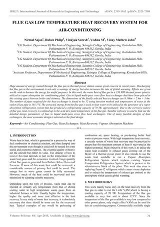
  • 2. IJRET: International Journal of Research in Engineering and Technology eISSN: 2319-1163 | pISSN: 2321-7308 _______________________________________________________________________________________ Volume: 04 Issue: 04 | Apr-2015, Available @ http://www.ijret.org 72 effect VAM does not require very high temperature and works on the temperature in the range 80-120℃ and its COP varies from 0.6 to 0.8. COP of VAM chosen is 0.7. Fig. 1. Isometric view of the flue gas low temperature heat recovery system In order to produce 70 TR, 350 KW of heat is supplied to the generator of the VAM. So we designed a Multi-pass Gas to Water heat exchanger to recover waste heat from flue gas to produce Air conditioning effect. Shape of the heat exchanger is selected as serpentine and contains 12 pipes each of 10 cm diameter. The diameter of the pipe is selected based on the predetermined calculations. Fig. 1. shows the model of the heat exchanger used for this purpose. The 1:1 model of the heat exchanger as well as the water flow simulation was done using Solidworks software. The flow analysis through the tubes as well as the optimization of the number of the tubes was done using ANSYS FLUENT software on a 1: 10 model of the heat exchanger using iteration method. Only a single pipe is considered for analysis because the dimensions of each of the pipe as well as the properties of flow through each of the pipes are the same. Before finding the outlet water temperature of the heat exchanger using ANSYS Fluent Software following assumptions are considered regarding the flow of water through the heat exchanger and they are, • Fully developed flow • Steady flow • Incompressible flow • Laminar flow • There will be perfect mixing of different layers of water occurring at the bend of pipes in heat exchanger. In this iteration method, the input temperature of water passes to the first pipe of heat exchanger is taken as ambient temperature of 300 K and its corresponding output temperature is found out by taking the arithmetic average of temperatures of different layers at the outlet of the pipe available using the ANSYS software. At the bend of the first pipe we assumed that perfect mixing of different layers of water is occurred so as to get a uniform water temperature. Then the outlet water temperature of first pipe of heat exchanger is taken as the input of the second pipe and again the output temperature of water is found out. This process is continued until the desired water output temperature is available at the outlet of the twelfth pipe which is about 374.1 K. In order to compensate heat losses due to friction due to bend of pipes and pipe wall, required temperature to be supplied to generator in the VAM is taken as 400 KW instead of 350 KW which was the calculated value. This Gas to Water Cross flow Heat Exchanger is to be placed in the space between boiler and chimney. The hot flue gas coming out from boiler passes across the cross flow multi pass heat exchanger and thus heats the water inside the heat exchanger. This flue gas after passing across the heat exchanger will goes out of the chimney. The hot water serves as an input to the Vapour Absorption Machine (VAM) driving Li-Br cycle to produce the desired air conditioning. Thermal and structural stress effects need not be considered at pressures below 15 atm or temperatures below 150°C.Thus the thermal and structural analysis of the heat exchanger is not carried out in this work. But these effects are major considerations above 70 atm or 550°C and seriously limit the acceptable materials of the heat exchanger. The common materials used for fabrication of industrial heat exchangers are aluminum, copper, stainless steel and high carbon steel. Since this work involves low temperature heat recovery, stainless steel and high carbon steel are not considered as they are commonly used in high temperature application and are very costly. Table 1. shows the comparison of properties of Aluminum and Copper which are the possible options for material for the heat exchanger. Since this heat recovery is in the very low temperature and also aluminum is less denser it is the most suitable choice. Table 1. Comparison of Physical Properties of Materials Material Density Melting Point Boiling Point Aluminium 2.70 g·cm−3 660.32 °C 2470 °C Copper 8.96 g·cm−3 1084.62 °C 2562 °C The heat exchanger is to be installed in the space between the boiler and chimney. The region is rectangular in cross section with a dimension of 1.25m × 7.48m × 17.4m. The dimensions of the final design of the heat exchanger is 0.106m× 2.4m× 3.4m. The heat exchanger is to be installed in a similar way as that of the radiator in an automobile i.e. each tube pass of the heat exchanger intercepts the flow of the flue gas as it flows from the boiler to the chimney. 3. ANALYTICAL SETUP The system consists of a water reservoir with makeup feed arrangement, pump, heat exchanger, vapour absorption refrigeration system and cooling tower, all of which are connected by pipes of suitable dimensions. Fig. 2. shows the detailed sketch of the proposed system. This paper
  • 3. IJRET: International Journal of Research in Engineering and Technology eISSN: 2319-1163 | pISSN: 2321-7308 _______________________________________________________________________________________ Volume: 04 Issue: 04 | Apr-2015, Available @ http://www.ijret.org 73 encompasses the design and analysis of the heat exchanger only. The specification of the VAM will be adopted according to the cooling load requirement of the building under consideration and the potential of the flue gas available at the plant. The heat exchanger will be designed to provide the necessary input to the VAM so as to deliver the desired air conditioning effect. The specifications of the remaining part of the system i.e. the reservoir, the pump and the connecting pipes is to be chosen according to the flow requirement of the system. Fig. 2. Detailed sketch of analytical setup 3.1 Working Process The system is proposed for waste heat recovery in a cascade process so that the heat recovery process will be efficient. The working process is intended for maximum heat recovery from the flue gas which is at a temperature of 125℃, which is a very low temperature compared to that of most of the thermal power plants. At this very low temperature the thermal and structural effects on the heat exchanger to be designed can be neglected. The working fluid selected is water because of its relative abundance and its non-toxic nature along with its high heat capacity. The process begins when the heat exchanger installed in the space between the boiler and the chimney taps the heat from the flue gas. The flue gas comes out of two of the combustion chambers coupled to each of the two gas turbines installed in the plant. The temperature of the flue coming out of the turbines are of the order of 550±50℃. This being a very high temperature is effectively used to generate steam in a HRSG (Boiler).The generated steam is then used to run a steam turbine, thus making the power plant a combined cycle power plant. The temperature of the flue reduces to almost 125℃ after rejecting heat to the boiler. This flue is made to flow across a multi - pass cross flow heat exchanger. The flue gas after rejecting heat to the heat exchanger passes through the chimney. A pump of predetermined mass flow rate is used to transfer water from a reservoir to the heat exchanger which heats up to the desired temperature through a cascade process involving multi-pass tubes of the heat exchanger. The heated water is then pushed forward by the pressure existing in the system to the generator part of the VAM which have a capacity of 70 TR and a COP of 0.7. The water coming out of VAM which is still at a considerable temperature is brought to ambient temperature by passing it through the cooling tower which is already present at the plant. The cooled water is then returned to the reservoir from where it is again pumped by the water pump. A make- up feed water arrangement is also provided with the reservoir to compensate for any losses. 4. DESIGN DATA The heat exchanger is designed according to the VAM requirements. So firstly, the amount of heat that is to be supplied to the generator of the VAM is to be found out. The available inputs are the capacity of the required system and its coefficient of performance. 4.1 Heat to be supplied to the Generator of VAM The heat to be supplied to the generator of VAM can be found out by the equation, COP = QE QG (1) where QG is the heat to be supplied to the generator of VAM,QE is the heat absorbed in the evaporator and COP is the coefficient of performance. 4.2 Outlet Temperature of Flue Gas The outlet temperature of the flue gas is found out using the equation, Q = mCp∆T = mCp (Tin – Tout) (2) where Q is the heat transferred from flue gas to water, m is the mass flow rate of flue gas, Cp is the specific heat capacity of flue gas, Tin is the inlet temperature of flue gas and Tout is the outlet temperature of flue gas. 4.3 Logarithmic Mean Temperature Difference (LMTD) The next important step is finding out the LMTD of the heat exchanger, which is given by LMTD = ∆Tm = ∆𝑇𝑖− ∆𝑇𝑒 ln ∆𝑇𝑖 ∆𝑇𝑒 (3) where, ∆𝑇𝑖 = Th1 – Tc2 (4)
  • 4. IJRET: International Journal of Research in Engineering and Technology eISSN: 2319-1163 | pISSN: 2321-7308 _______________________________________________________________________________________ Volume: 04 Issue: 04 | Apr-2015, Available @ http://www.ijret.org 74 ∆𝑇𝑒 = Th2 – Tc1 (5) where Th1 and Th2 are the inlet and outlet temperatures of the flue gas and Tc1 and Tc2 are the corresponding values of water. 4.4 Surface Area of the Heat Exchanger Area of the heat exchanger is found out using the equation, Heat transfer, Q = UFA∆Tm (6) where, U is the overall heat transfer coefficient, in W/m2 °C, A is the surface area of the heat exchanger in m2 and ∆Tm is the LMTD in ℃ and F is the correction factor. 4.5 Mass Flow Rate of Water through Heat Exchanger We know that heat transfer, Q = mCpw ∆T = mCpw (Tout − Tin ) (7) where, m is the mass flow rate of water in Kg/sec, Q is the heat transfer in KW, Cpw is the specific heat capacity of water, Tin is the inlet temperature of water in ℃ and Tout is the outlet temperature of water in ℃. 4.6 Number of Tubes, Diameter and Length of the Pipe For a heat exchanger consisting of n tubes, the total surface area is given by, A = πdLn (8) where, d is the diameter of the tubes, L is the length of a single tube. From the above equation the values of d, L, n are optimised using iteration by taking different values for d, n and L for a constant surface area and the optimised values are; d = 10cm L = 2m n = 11 4.7 Velocity of Water through the Pipes It is clear that mass flow rate, 𝑚 = 𝜌𝐴 𝑐 𝑉 (9) where, ρ is the density of water in Kg/m3 , Ac is the cross sectional area of heat exchanger, in m2 and V is the velocity of water through heat exchanger in m/s. 4.8 Energy Savings Power required for operating VCM =78.2985 KW Power required for operating VAM = 2% of VCM =1.566 KW Total Power Saved = 78.2985 – 1.566 = 76.732 KW Energy saved if air-conditioner works 12 hours per day = 76.732 × 12 = 920.784 KWhr = 920.784 Units/day. 5. ANALYSIS The heat exchanger analysis is being carried out using ANSYS FLUENT software. Although the design involves a multi-pass heat exchanger consisting of twelve pipes, the analysis is carried out only on the first and the last pipe of the heat exchanger. This is because the properties of flue gas flowing through the space between boiler and chimney and the water flowing through the pipe respectively are same for each pipe. The dimensions of the heat exchanger is being scaled down to one – tenth of its original dimensions due to considerable difficulty faced during the analysis of 1:1 model of the heat exchanger. But the resulting error will be only one percent. A rectangular control volume of cross sectional area of 30 𝑐𝑚2 is also considered which encloses the pipe. The flow analysis of both the cold fluid and the hot fluid is being carried out in the control volume considered. 5.1 Velocity Analysis Since the velocity of flow of flue gas across the heat exchanger and the velocity of water flowing through each pipes are the same, only a single pipe including the control volume is being analysed. The velocity of flow of the flue gas and water can be theoretically found out using their known mass flow rates. These can be essentially used as inputs for software analysis. The solution obtained from the software is obtained as a streamline simulation.
  • 5. IJRET: International Journal of Research in Engineering and Technology eISSN: 2319-1163 | pISSN: 2321-7308 _______________________________________________________________________________________ Volume: 04 Issue: 04 | Apr-2015, Available @ http://www.ijret.org 75 Fig. 3. Velocity streamlines of both flue gas and water Fig. 3. shows the velocity streamlines of both flue gas and water. From the figure, it can be understood that the velocity of flue gas increases when it approaches the pipe and decreases when it passes the pipe. It may be due to, the reduction in area that occurs when the flue gas approaches the pipe and the subsequent reduction in pressure. As the flow area increases the velocity of the flue gas decreases correspondingly. Fig. 4. shows the velocity streamline of flue gas only. From the figure it can be inferred that the velocity of the flue gas directly below the pipe is almost zero. This may be due to the near stagnation condition that arises at that region. This is mainly because of the fact that the particular layer of flue gas has less chance to escape due to the obstruction created by the pipe and the continuous collision with fresh flue gas which nearly impedes its motion. Thus there is less chance of fresh flue gas interaction with the pipe wall at this region. Fig. 4. Velocity Streamline of Flue Gas
  • 6. IJRET: International Journal of Research in Engineering and Technology eISSN: 2319-1163 | pISSN: 2321-7308 _______________________________________________________________________________________ Volume: 04 Issue: 04 | Apr-2015, Available @ http://www.ijret.org 76 Fig. 5. shows the velocity contour plot of water flow at the outlet of the first pipe. The plot gives the velocity variation in the radial direction. It can also be inferred from the figure that the velocity of water layers close to the pipe boundary is low as compared to the velocity of water layer passing through the center of the pipe. This is due to the viscous effects that becomes prominent as the proximity to the pipe wall increases. Fig. 5. Velocity contour at the outlet of pipe The velocity analysis is the basis for all other subsequent analysis in this work. The variations in velocity is the prime determinant for the variation of properties like Temperature and Pressure all across the control volume. It is clear from the figure that although the velocities of the flue gas and water involved are small, but they are sufficient enough to bring a considerable amount of heat transfer in this work. Many works states that minimizing the pressure drop and the mass flow rate of the fluids will minimize the operating cost of the heat exchanger, but it will maximize the size of the heat exchanger and thus the initial cost. As a rule of thumb, doubling the mass flow rate will reduce the initial cost by half but will increase the pumping power requirements by a factor of roughly eight. Low velocities are helpful in avoiding erosion, tube vibrations, and noise as well as pressure drop. 5.2 Temperature Analysis Temperature analysis is carried out by considering only the inner wall of the pipes 1 and 12. Other pipes are not considered. This is because all the pipes exhibit same behavior. Fig. 6. Temperature contour of the inner wall of pipe 1
  • 7. IJRET: International Journal of Research in Engineering and Technology eISSN: 2319-1163 | pISSN: 2321-7308 _______________________________________________________________________________________ Volume: 04 Issue: 04 | Apr-2015, Available @ http://www.ijret.org 77 Fig. 6. shows the temperature contour across inner wall of pipe 1. From the figure we can see that top surface of pipe 1 shows higher temperature than the bottom surface or any other surface. It may be due to the vortex flow created by the flue gas due to the curved shape of the pipes, so that flue gas molecules from both sides hits the top surface of pipe. This causes higher temperature of top surface than any other surface. Temperature of the top surface is almost same as the flue gas which is at 125℃. It is through the wall of the pipe heat passes to water inside the pipe. Fig. 7. shows the temperature contour of inner wall of pipe 12. From this pipe we can see that temperature is same at all regions of the wall. Water enters the last pipe after passing through all the 11 pipes and the temperature of water goes on increasing as it pass through each pipe since it is a multi-pass heat exchanger. High temperature water at about 95℃ enters into the last pipe. Since temperature of the water is very high, heat from the walls is distributed to the walls of the pipe. Also wall is heated due to temperature of flue gas. This may be the reason that inner wall of pipe has higher temperature at all its regions. Fig. 7. Temperature contour of the inner wall of pipe 12 6. RESULTS AND DISCUSSIONS 6.1 Temperature at Outlet of Each Pipe The temperature at the outlet of each pipe is taken as an average value of temperatures at each section considered along the radial direction. This is because the temperature at any particular section cannot represent the outlet temperature correctly. These temperatures are obtained by plotting charts at each considered section. The average temperatures at the outlet of each pipes of the heat exchanger are shown in the Table 2. The temperature of water entering the first pipe is taken as ambient temperature, which is 300K. Finally at the end of the last pipe, the average outlet temperature is almost 374.1K. The iteration procedure is stopped at the twelfth pipe mainly due to two reasons. The first reason is that unlike all the other eleven preceding pipes the temperature rise in the twelfth pipe is a mere 2℃ compared to five in all the other tubes, thus it is useless continuing the iteration procedure any further. The second reason is that the outlet temperature of the twelfth pipe is almost 374.1 K which vaporises a small quantity of water to steam which is undesirable. This value is different from the theoretical outlet temperature of water (363K). Thus along with maximum possible heat transfer, this design also provides a factor of safety for the design. Table 2. Average outlet temperatures of different pipes. Pipe No. Inlet Temperature (K) Outlet Temperature (K) 1 300 309.6 2 309.6 320.3 3 320.3 325.1 4 325.1 333.6 5 333.6 341.4 6 341.4 347.7 7 347.7 353.6 8 353.6 359.1 9 359.1 363.6 10 363.6 368 11 368 371.5 12 371.5 374.1
  • 8. IJRET: International Journal of Research in Engineering and Technology eISSN: 2319-1163 | pISSN: 2321-7308 _______________________________________________________________________________________ Volume: 04 Issue: 04 | Apr-2015, Available @ http://www.ijret.org 78 6.2 Temperature vs. Radial Distance (pipe 1) Fig. 8. Temperature variation along the radial direction at the outlet of pipe 1 The graph of Temperature vs. Radial distance at the outlet of the first pipe is shown in the Fig. 8. This chart gives an idea about the variation of temperature with radial distance above and below the axis of the pipe. From the graph it is clear that temperature is maximum at the top and bottom of the pipe and there will be almost no change in the temperature along the centre portion of the pipe (+3.5 to -3.5 cm). This may be due to the fact that the flue gas transfers its heat to the walls of the pipes and the water layer that is nearer to the boundary stays there long due to viscous effects as compared to the fluid layers at the centre and gets heated up. The velocity of the fluid layer at the center will be more thus there is less chance for heat transfer between the different layers of fluid in that region. Temperature of water layer close to the top boundary is more as compared to that of bottom layer. This may be due to the reason cited earlier i.e. the stagnation condition existing below the heat exchanger pipe. Thus the stagnant layer of flue gas prevents the transfer of heat by fresh flue gas. But the top surface will always face a fresh flue gas flow (Vortex flow) thus increasing the boundary temperature there. 6.3 Temperature vs. Longitudinal Distance Fig. 9. Temperature variation along the length of pipe 1 close to the pipe wall The temperature vs. longitudinal distance curve for the first pipe at a section close to the pipe wall region is shown in the Fig. 9. It shows the variation of temperature along the length of the tube. Only a single section is considered for analysis because the charts considered along different sections along the length have same trends. From the graph it is clear that, the temperature is not uniform throughout the length of the pipe. Both increase and decrease in the temperature can be seen from the chart. This may be due to the temperature gradient existing between different layers of the fluid. As a result there will be density gradient at different layers of the fluid. This causes random movement of fluid molecules thus distributing temperatures unevenly. 6.4 Temperature vs. Radial Distance (pipe 12) The graph showing Temperature vs. Radial distance for the last pipe is shown in the Fig. 10. It can be easily noticed that the pattern of the curve is very much similar to the curve shown in figure 8. Only difference is that the temperature at the top and bottom layer are comparable in this case .This may be due to the high temperature of water entering the twelfth pipe unlike the first pipe. All the other pipes will be showing similar trends like that of Fig. 8 and Fig. 9, except that there operating temperature will be different.
  • 9. IJRET: International Journal of Research in Engineering and Technology eISSN: 2319-1163 | pISSN: 2321-7308 _______________________________________________________________________________________ Volume: 04 Issue: 04 | Apr-2015, Available @ http://www.ijret.org 79 Fig. 10. Temperature variation along the radial direction at the outlet of pipe 12 7. CONCLUSION As the energy demand in our day to day life escalates significantly, there are plenty of energies are shuffled in the universe. Energies are put in an order of low grade and high grade energies. The regeneration of low grade energy into some beneficial work is a fantastic job. One such low grade energy is heat energy. So it is imperative that a significant and concrete effort should be taken for using heat energy through waste heat recovery. This work focuses on tapping the unused heat energy from flue gas and using the same for day-to-day applications, in this case for air conditioning application. The main conclusion that can be drawn from this work is the relative advantage that a VAM has over the VCM. The dimensions of the final design of the heat exchanger was obtained as 0.106 m × 2.4 m × 3.4 m. The finally optimized total number of pipes was 12 and it was found that further increase in the number of pipes is not justifiable because the rise in water temperature per pipe is not above 1℃.The optimized total length and pipe diameter of the heat exchanger was obtained as 30 m and 0.1 m respectively. The required mass flow rate of water through the heat exchanger is 1.516 kg/sec and the average outlet temperature of last pipe is 101.1 ℃. The temperature of water exiting the heat exchanger is potential enough to run a single effect Vapour Absorption Machine. The final proposed Vapour Absorption Machine effectively replaces the exiting Vapour Compression Machine. REFERENCES [1] K. Balaji and R. Senthil Kumar, “Study of Vapour Absorption System Using Waste Heat in Sugar Industry,” IOSR Journal of Engineering (IOSRJEN), Volume 2, Issue 8, pp. 34-39, 2012. [2] Ramesh K. Shah and Dusan P. Sekulic, Fundamentals of Heat Exchanger Design, John Wiley & Sons, Inc., 1st Edn., Hoboken, New Jersey,2003. [3] Kuppan Thulukkanam, Heat Exchanger Design Handbook, CRC Press, 2nd Edn., Boca Raton, 2013. [4] R. K. Rajput, Heat and Mass Transfer, S. Chand, 5th Edn., New Delhi, 2014. [5] R. S. Khurmi and J.K. Gupta, A Textbook of Refrigeration and Air Conditioning, S. Chand, 5th Edn., New Delhi, 2014.