Downloaded 156 times
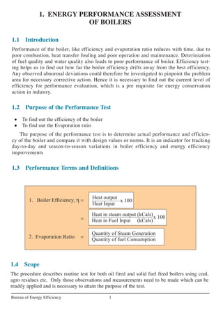
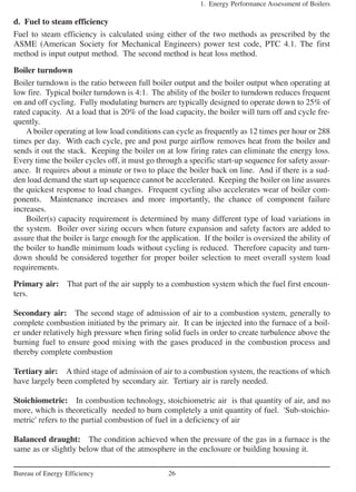
![6. Heat loss due to radiation and convection:
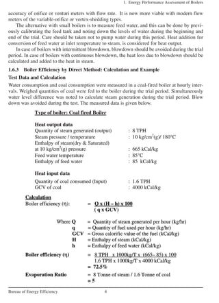
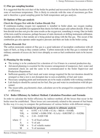
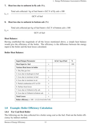
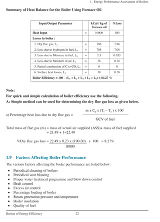
The other heat losses from a boiler consist of the loss of heat by radiation and convection from
the boiler casting into the surrounding boiler house.
Normally surface loss and other unaccounted losses is assumed based on the type and size
of the boiler as given below
For industrial fire tube / packaged boiler = 1.5 to 2.5%
For industrial watertube boiler = 2 to 3%
For power station boiler = 0.4 to 1%
However it can be calculated if the surface area of boiler and its surface temperature are
known as given below :
1. Energy Performance Assessment of Boilers
12Bureau of Energy Efficiency
%CO x C 5744
L5 = x x 100
% CO + % CO2 GCV of fuel
L5 = % Heat loss due to partial conversion of C to CO
CO = Volume of CO in flue gas leaving economizer (%)
CO2 = Actual Volume of CO2 in flue gas (%)
C = Carbon content kg / kg of fuel
or
When CO is obtained in ppm during the flue gas analysis
CO formation (Mco) = CO (in ppm) x 10–6
x Mf x 28
Mf = Fuel consumption in kg/hr
L5 = Mco x 5744*
* Heat loss due to partial combustion of carbon.
L6 = 0.548 x [ (Ts / 55.55)4
– (Ta / 55.55)4
] + 1.957 x (Ts – Ta)1.25
x sq.rt of
[(196.85 Vm + 68.9) / 68.9]
where
L6 = Radiation loss in W/m2
Vm = Wind velocity in m/s
Ts = Surface temperature (K)
Ta = Ambient temperature (K)
Heat loss due to unburned carbon in fly ash and bottom ash:
Small amounts of carbon will be left in the ash and this constitutes a loss of potential heat in
the fuel. To assess these heat losses, samples of ash must be analyzed for carbon content. The
quantity of ash produced per unit of fuel must also be known.](https://image.slidesharecdn.com/4ch1-130626012024-phpapp02/85/4-ch1-12-320.jpg)
![1. Energy Performance Assessment of Boilers
14Bureau of Energy Efficiency
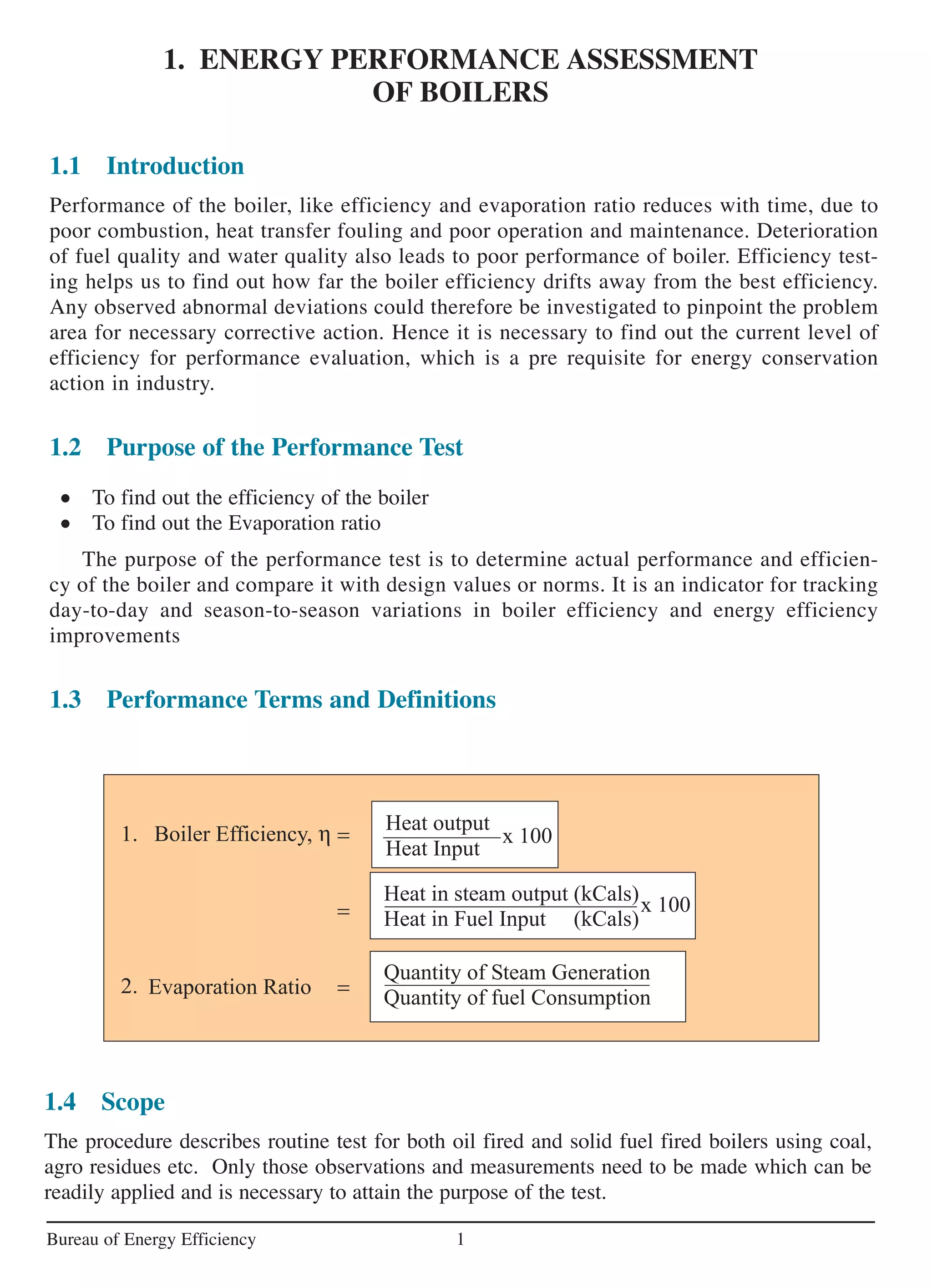
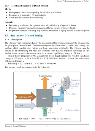
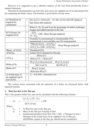
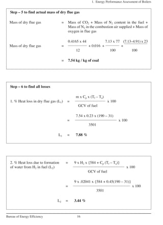
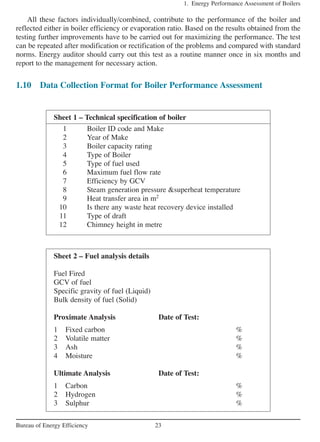
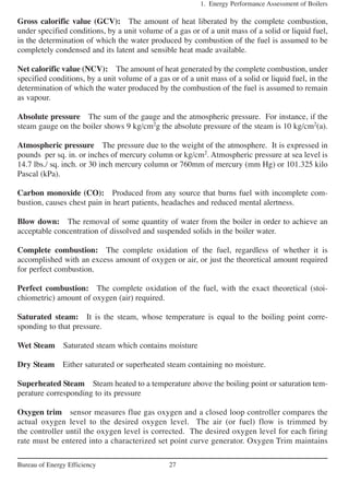
Fuel firing rate = 5599.17 kg/hr
Steam generation rate = 21937.5 kg/hr
Steam pressure = 43 kg/cm2
(g)
Steam temperature = 377 °C
Feed water temperature = 96 °C
%CO2 in Flue gas = 14
%CO in flue gas = 0.55
Average flue gas temperature = 190 °C
Ambient temperature = 31 °C
Humidity in ambient air = 0.0204 kg / kg dry air
Surface temperature of boiler = 70 °C
Wind velocity around the boiler = 3.5 m/s
Total surface area of boiler = 90 m2
GCV of Bottom ash = 800 kCal/kg
GCV of fly ash = 452.5 kCal/kg
Ratio of bottom ash to fly ash = 90:10
Fuel Analysis (in %)
Ash content in fuel = 8.63
Moisture in coal = 31.6
Carbon content = 41.65
Hydrogen content = 2.0413
Nitrogen content = 1.6
Oxygen content = 14.48
GCV of Coal = 3501 kCal/kg
Boiler efficiency by indirect method
Step – 1 Find theoretical air requirement
Theoretical air required for = [(11.6 x C) + {34.8 x (H2 – O2/8)} + (4.35 x S)] /100
complete combustion kg/kg of coal
= [(11.6 x 41.65) + {34.8 x (2.0413 – 14.48/8)} +
(4.35 x 0)] / 100
= 4.91 kg / kg of coal](https://image.slidesharecdn.com/4ch1-130626012024-phpapp02/85/4-ch1-14-320.jpg)
![1. Energy Performance Assessment of Boilers
15Bureau of Energy Efficiency
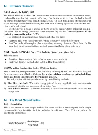
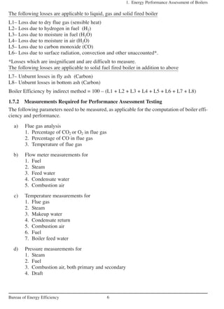
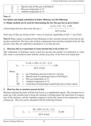
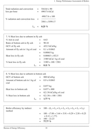
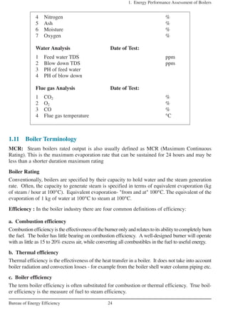
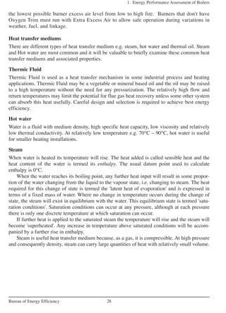
Step – 3 To find Excess air supplied
Actual CO2 measured in flue gas = 14.0%
7900 x [ ( CO2%)t – (CO2%)a]
% Excess air supplied (EA) =
(CO2%)a x [100 – (CO2%)t ]
7900 x [20.37 – 14 ]
=
14a x [100 – 20.37]
= 45.17 %
Step – 4 to find actual mass of air supplied
Actual mass of air supplied = {1 + EA/100} x theoretical air
= {1 + 45.17/100} x 4.91
= 7.13 kg/kg of coal](https://image.slidesharecdn.com/4ch1-130626012024-phpapp02/85/4-ch1-15-320.jpg)
![1. Energy Performance Assessment of Boilers
17Bureau of Energy Efficiency
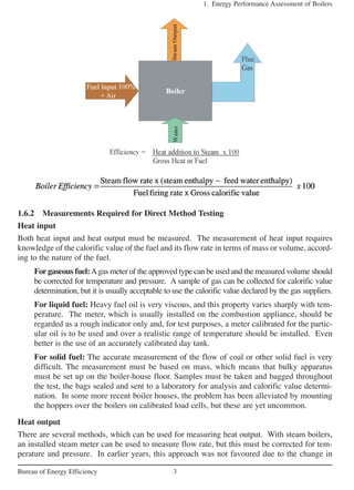
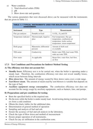
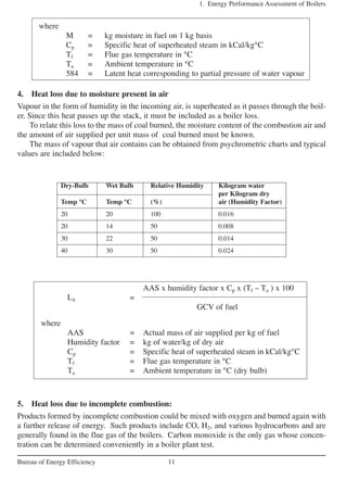
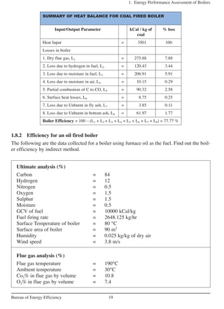
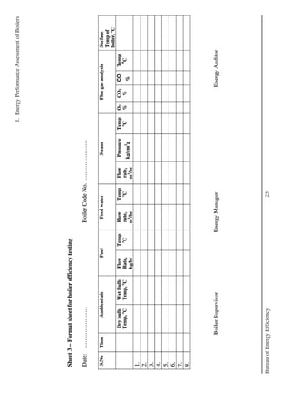
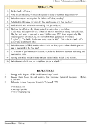
M x {584 + Cp ( Tf – Ta )}
3. % Heat loss due to moisture in = X 100
fuel (L3) GCV of fuel
0.316 x {584 + 0.45 ( 190 - 31) }
= x 100
3501
L3 = 5.91 %
AAS x humidity x Cp x (Tf – Ta ) x 100
4. % Heat loss due to moisture =
in air (L4) GCV of fuel
7.13 x 0.0204 x 0.45 x (190 – 31) x 100
=
3501
L4 = 0.29 %
%CO x C 5744
5. % Heat loss due to partial = x x 100
conversion of C to CO (L5) % CO + (% CO2)a GCV of fuel
0.55 x 0.4165 5744
= x x 100
0.55 + 14 3501
L5 = 2.58 %
6. Heat loss due to radiation and = 0.548 x [ (343/55.55)4
– (304/55.55)4
] + 1.957 x
convection (L6) (343 – 304)1.25
x sq.rt of [(196.85 x 3.5 + 68.9) / 68.9]
= 633.3 w/m2
= 633.3 x 0.86
= 544.64 kCal / m2](https://image.slidesharecdn.com/4ch1-130626012024-phpapp02/85/4-ch1-17-320.jpg)
![1. Energy Performance Assessment of Boilers
20Bureau of Energy Efficiency
a) Theoretical air required = [(11.6 x C) + [{34.8 x (H2 – O2/8)} + (4.35 x S)] /100
kg/kg of fuel. [from fuel analysis]
= [(11.6 x 84) + [{34.8 x (12 – 1.5/8)}
+ (4.35 x 1.5)] / 100
= 13.92 kg/kg of oil
b) Excess Air supplied (EA) = (O2 x 100) / (21 – O2)
= (7.4 x 100) / (21 – 7.4)
= 54.4 %
c) Actual mass of air supplied/ kg = {1 + EA/100} x theoretical air
of fuel (AAS)
= {1 + 54.4/100} x 13.92
= 21.49 kg / kg of fuel
Mass of dry flue gas = Mass of (CO2 + SO2 + N2 + O2) in flue gas + N2
in air we are supplying
0.84 x 44 0.015 x 64
12 32
= 21.36 kg / kg of oil
m x Cp x (Tf – Ta)
% Heat loss in dry flue gas = x 100
GCV of fuel
21.36 x 0.23 x (190 – 30)
= x 100
10000
L1 = 7.86 %
9 x H2 x{584 + Cp (Tf – Ta )}
Heat loss due to evaporation of = x 100
water due to H2 in fuel (%) GCV of fuel
9 x 0.12 x {584 + 0.45 (190 – 30)}
= x 100
10000
L2 = 7.08 %
+ 0.005 + +
7.4x23
100
21.49 x 77
100
+=](https://image.slidesharecdn.com/4ch1-130626012024-phpapp02/85/4-ch1-20-320.jpg)
![1. Energy Performance Assessment of Boilers
21Bureau of Energy Efficiency
M x {584 + Cp ( Tf - Ta )}
% Heat loss due to moisture = X 100
in fuel GCV of fuel
0.005 x {584 + 0.45 (190 – 30)}
= x 100
10000
L3 = 0.033%
AAS x humidity x Cp x (Tf – Ta ) x 100
% Heat loss due to moisture in air =
GCV of fuel
21.36 x 0.025 x 0.45 x (190 – 30) x 100
=
10000
L4 = 0.38 %
Radiation and convection loss = 0.548 x [ (Ts / 55.55)4
– (Ta / 55.55)4
] + 1.957
(L6) x (Ts – Ta)1.25
x sq.rt of [(196.85 Vm + 68.9) / 68.9]
= 0.548 x [ (353 / 55.55)4
– (303 / 55.55)4
] + 1.957
x(353–303)1.25
xsq.rtof[(196.85x3.8+68.9)/68.9]
= 1303 W/m2
= 1303 x 0.86
= 1120.58 kCal / m2
Total radiation and convection = 1120 .58 x 90 m2
loss per hour = 100852.2 kCal
% Radiation and convection loss = 100852.2 x 100
10000 x 2648.125
L6 = 0.38 %
Normally it is assumed as 0.5 to 1 % for simplicity
Boiler efficiency by indirect = 100 – (L1 + L2 + L3 + L4 + L6)
method = 100 – (7.86 + 7.08 + 0.033 + 0.38 + 0.38)
= 100 – 15.73
= 84.27 %](https://image.slidesharecdn.com/4ch1-130626012024-phpapp02/85/4-ch1-21-320.jpg)

1. The performance of boilers decreases over time due to factors like poor combustion, fouling, and improper maintenance. Regular efficiency testing helps identify efficiency losses and issues in need of corrective action. 2. The purpose of a performance test is to determine the actual efficiency and evaporation ratio of a boiler and compare it to design specifications. It tracks variations in efficiency over time and the impact of energy efficiency improvements. 3. Boiler efficiency can be tested via the direct method, which compares energy output in steam to energy input in fuel burned, or the indirect method, which calculates efficiency as 100% minus the sum of measured heat loss factors. Both methods require measuring various operational parameters.


