Download as PDF, PPTX


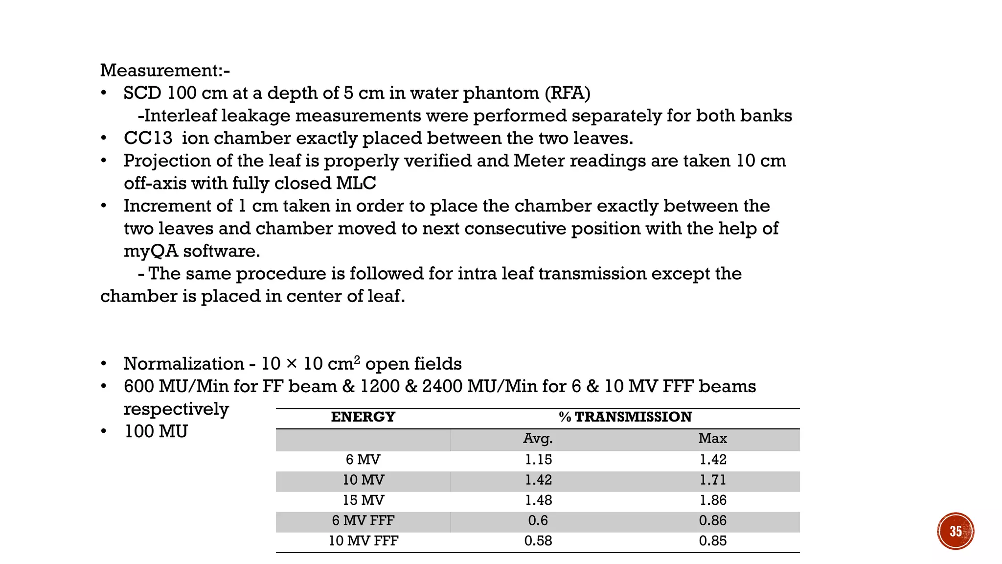
![Energy
With Couch
[MR(nC)]
Without Couch
[MR (nC) ]
Couch Trans.
Factor
Couch
Trans.
Factor
Thin Thick Thin Thick Thin Thick Avg
6MV 14.3 14.13 14.6 14.6 0.9795 0.9678 0.9736
10MV 15.98 15.84 16.22 16.22 0.9852 0.9766 0.9809
15MV 16.97 16.82 17.16 17.16 0.9889 0.9802 0.9846
6MV
FFF
13.7 13.52 14.01 14.01 0.9779 0.9650 0.9714
10MV
FFF
15.39 15.25 15.64 15.64 0.9840 0.9751 0.9795
23](https://image.slidesharecdn.com/projectvineeth-190412092242/75/Commissioning-of-Truebeam-LINAC-23-2048.jpg)


![COV = (1/ X )*[( (Xi- X)2 ) /(n-1)] ½
Set kV Output (mGy)
Avg X Σ(Xi-X)2 [Σ(Xi-X)2]/n-1 [[Σ(Xi-X)2]/n-1]1/2 COV
1 2 3
50 0.0615 0.0618 0.0613 0.0615 0.00000013 0.00000006 0.000251 0.00408
70 0.131 0.1313 0.1317 0.1313 0.00000024 0.00000012 0.000343 0.002613
80 0.173 0.1724 0.1722 0.1725 0.00000036 0.00000018 0.000422 0.002446
100 0.2618 0.2617 0.2613 0.2616 0.00000012 0.00000006 0.000247 0.000946
120 0.3599 0.3602 0.3584 0.3595 0.00000197 0.00000099 0.000994 0.002764
130 0.4106 0.4107 0.4116 0.411 0.0000006 0.0000003 0.000545 0.001327
140 0.4648 0.4654 0.4645 0.4649 0.00000021 0.00000021 0.000459 0.000987
41](https://image.slidesharecdn.com/projectvineeth-190412092242/75/Commissioning-of-Truebeam-LINAC-41-2048.jpg)


![▪ [1] Das, I.J., Cheng, C.W.,Watts, R.J., Ahnesjö, A.,
Gibbons, J., Li, X.A., Lowenstein, J., Mitra, R.K.,
Simon,W.E. and Zhu,T.C. (2008) Accelerator
Beam Data Commissioning Equipment and
Procedures: Report of the TG-106 of the Therapy
Physics Committee of the AAPM. Medical Physics,
35, 4186-4215.
http://dx.doi.org/10.1118/1.2969070
▪ [2] Nath, R., Biggs, P.J., Bova, F.J., Ling, C.C., Purdy,
J.A., van de Geijn, J. and Weinhous, M.S. (1994)
AAPM Code of Practice for Radiotherapy
accelerators: Report of AAPM Radiation Therapy
Task Group No. 45. Medical Physics, 21, 1093-
1121. (AAPM Report No. 47)
▪ [3] Sahani, G., Sharma, S.D., Sharma, P.K.,
Deshpande, D.D., Negi, P.S., Sathianarayanan,V.K.
and Rath, G.K. (2014) Acceptance Criteria for
Flattening Filter-Free Photon Beam from Standard
Medical Electron Linear Accelerator: AERB Task
Group Recommendations. Journal of Medical
Physics, 39, 206-211.
http://dx.doi.org/10.4103/0971-6203.144482
▪ [4] Khan, F.M. (2003) Physics of Radiation Therapy.
3rd Edition, Lippincott Williams & Wilkins.
▪ 5] Musolino, S.V. (2000) Absorbed Dose
Determination in External Beam Radiotherapy: An
International Code of Practice for Dosimetry
Based on Standards of Absorbed Dose to Water.
Health Physics, 81, 592-593. (IAEA TRS-398)
▪ [6] Boyer, A., Biggs, P., Galvin, J., Klein, E., LoSasso,
T., Low, D., Mah, K. and Yu, C. (2001) Basic
Applications of Multileaf Collimator: Report of
Task Group No. 50 Radiation Therapy Committee.
American Association of Physicists in Medicine
(AAPM TG-50, 10) (AAPM Report No. 72).
46](https://image.slidesharecdn.com/projectvineeth-190412092242/75/Commissioning-of-Truebeam-LINAC-46-2048.jpg)
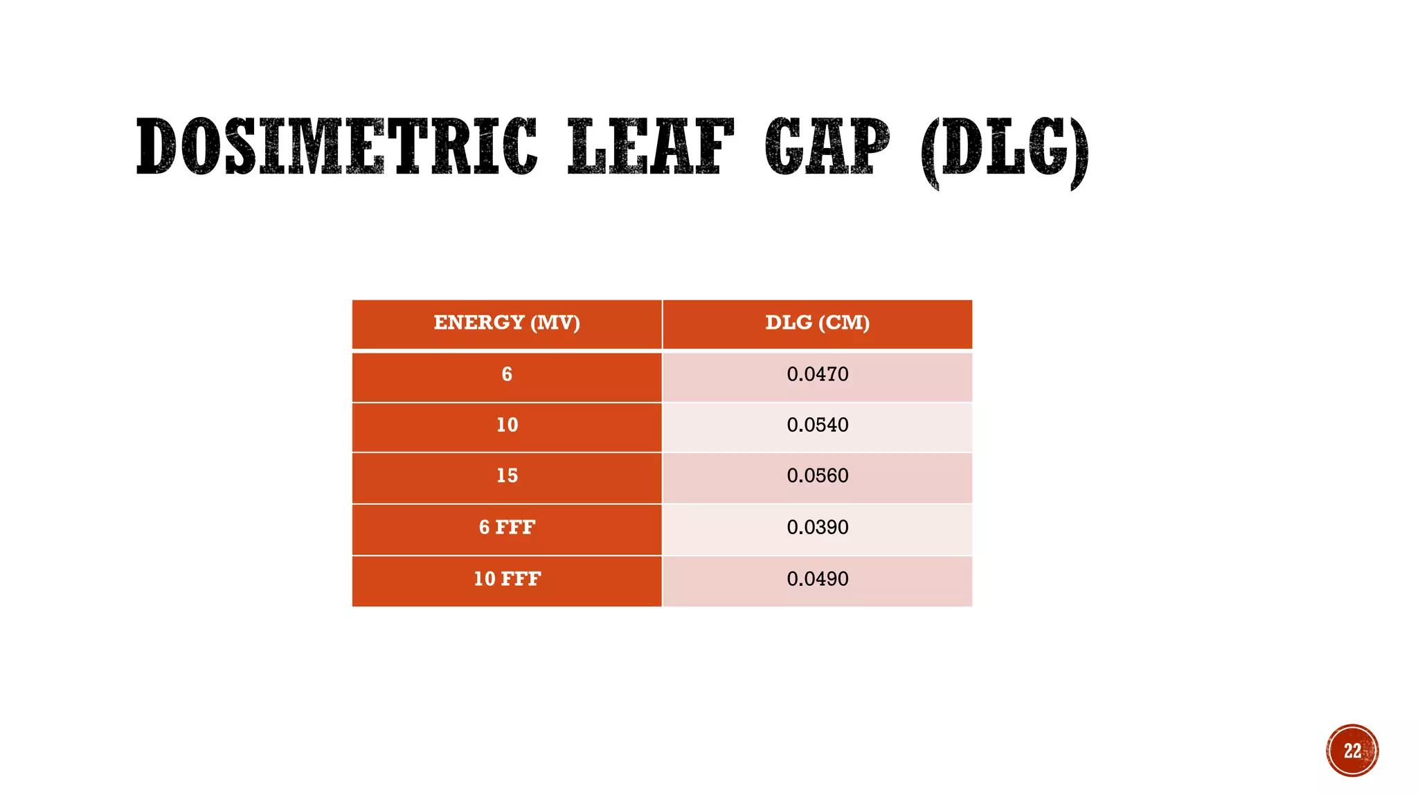
![[7]Dosimetric Leaf Gap Measurement, Procedure
Recommended by Varian Medical System.
Eclipse 10 Inverse Planning Administration and
Physics rev. 6.1.1.
[8] Szpala, S., Cao, F. and Kohli, K. (2014) On Using
the Dosimetric Leaf Gap to Model the Rounded
Leaf Ends in VMAT/RapidArc Plans. Journal of
Applied Clinical Medical Physics, 15, 4484.
[9] Acceptance/quality assurance tests for
Medical linear accelerator, RPAD/ACC/QA/04
[10]Absorbed dose determination In external
Beam radiotherapy An International Code of
Practice for Dosimetry Based on Standards of
Absorbed Dose to Water -TRS 398
[11]IEC 60601-2-1 Particular requirements for the
basic safety and essential performance of
electron accelerators in range 1 MeV to 50 MeV
[12] IAEA TRS-381 The use of plane-parallel
ionization chambers in high-energy electron and
photon beams. An international code of practice
for dosimetry
[13] K. R.Winston and W. Lutz,“Linear accelerator
as a neurosurgical tool for
stereotactic radiosurgery,” Neurosurgery 22, 454–
464 (1988).
[14] Commissioning and Acceptance Testing of
the existing linear accelerator upgraded to
volumetric modulated arc therapy - Ekambaram
Varadharajana and Velayudham
Ramasubramanian
[15] Shende, R., et al. (2016) Commissioning of
TrueBeamTM Medical Linear Accelerator:
Quantitative and Qualitative Dosimetric Analysis
and Comparison of Flattening Filter (FF) and
Flattening Filter Free (FFF) Beam. International
Journal of Medical Physics, Clinical Engineering
and Radiation Oncology, 5, 51-69.
47](https://image.slidesharecdn.com/projectvineeth-190412092242/75/Commissioning-of-Truebeam-LINAC-47-2048.jpg)


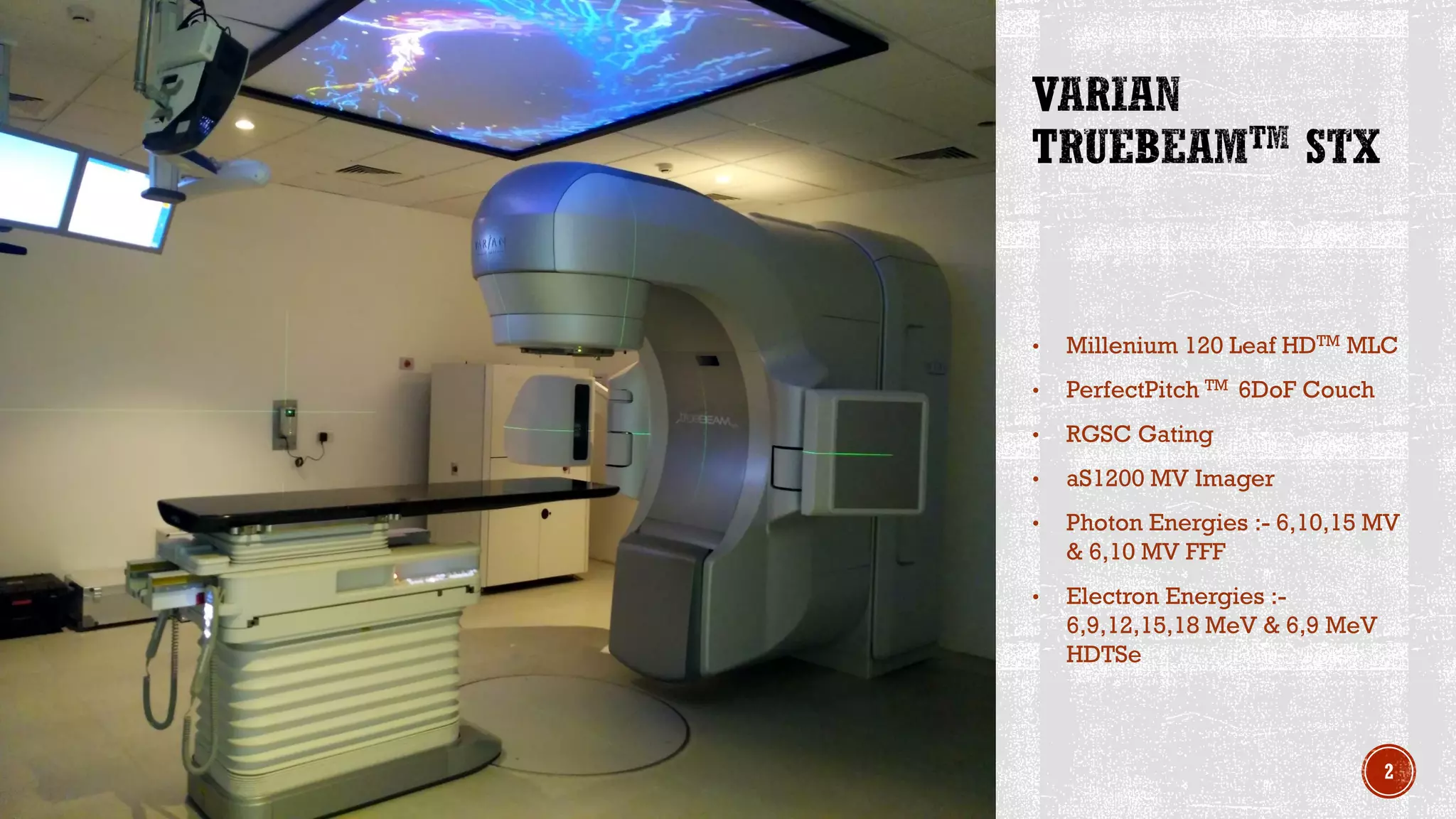
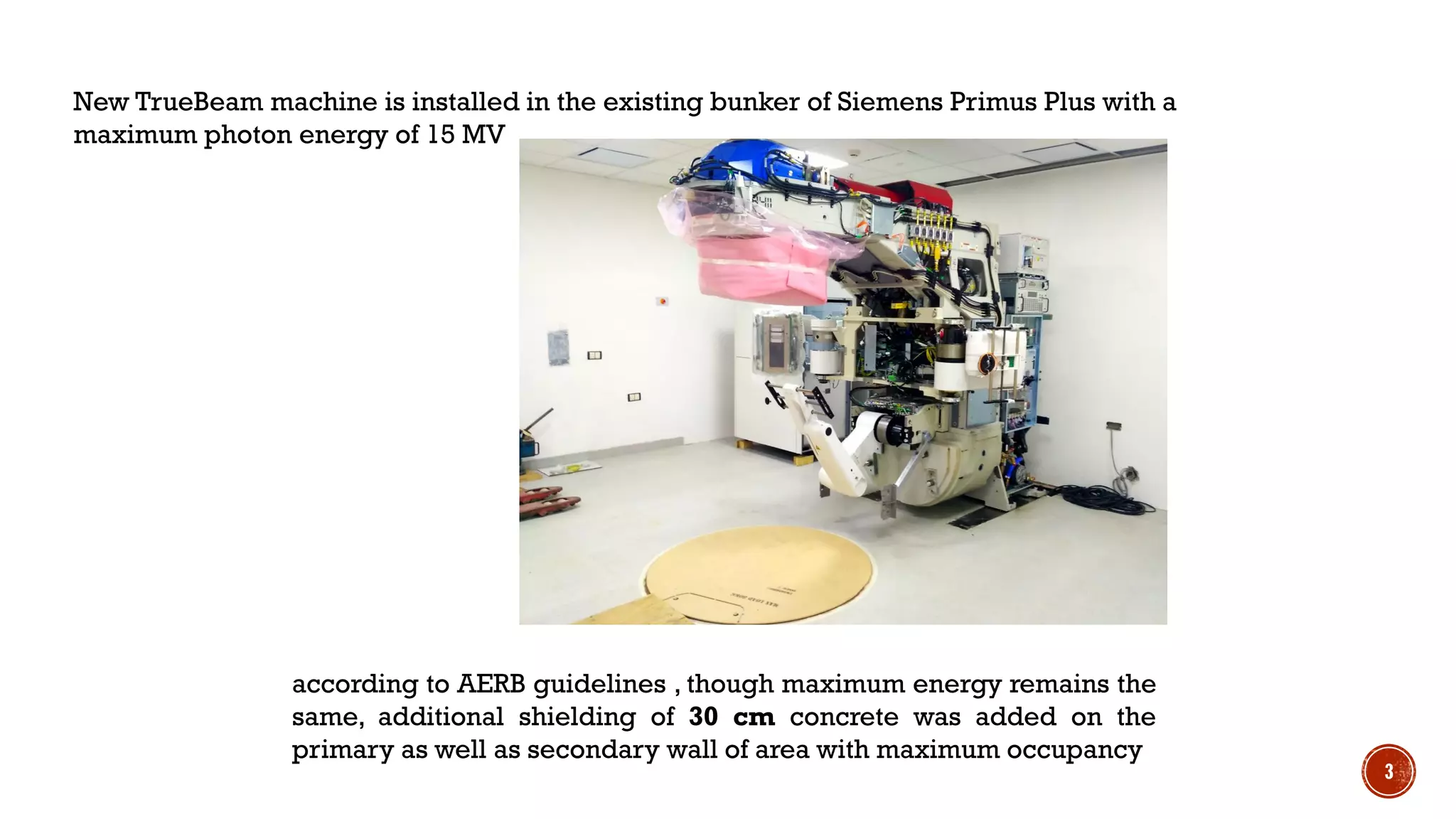
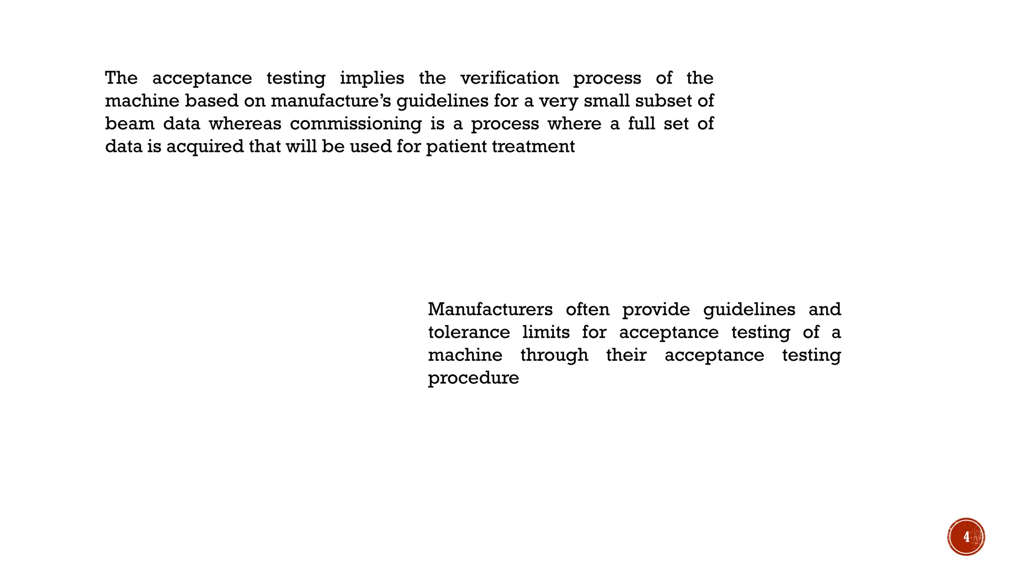
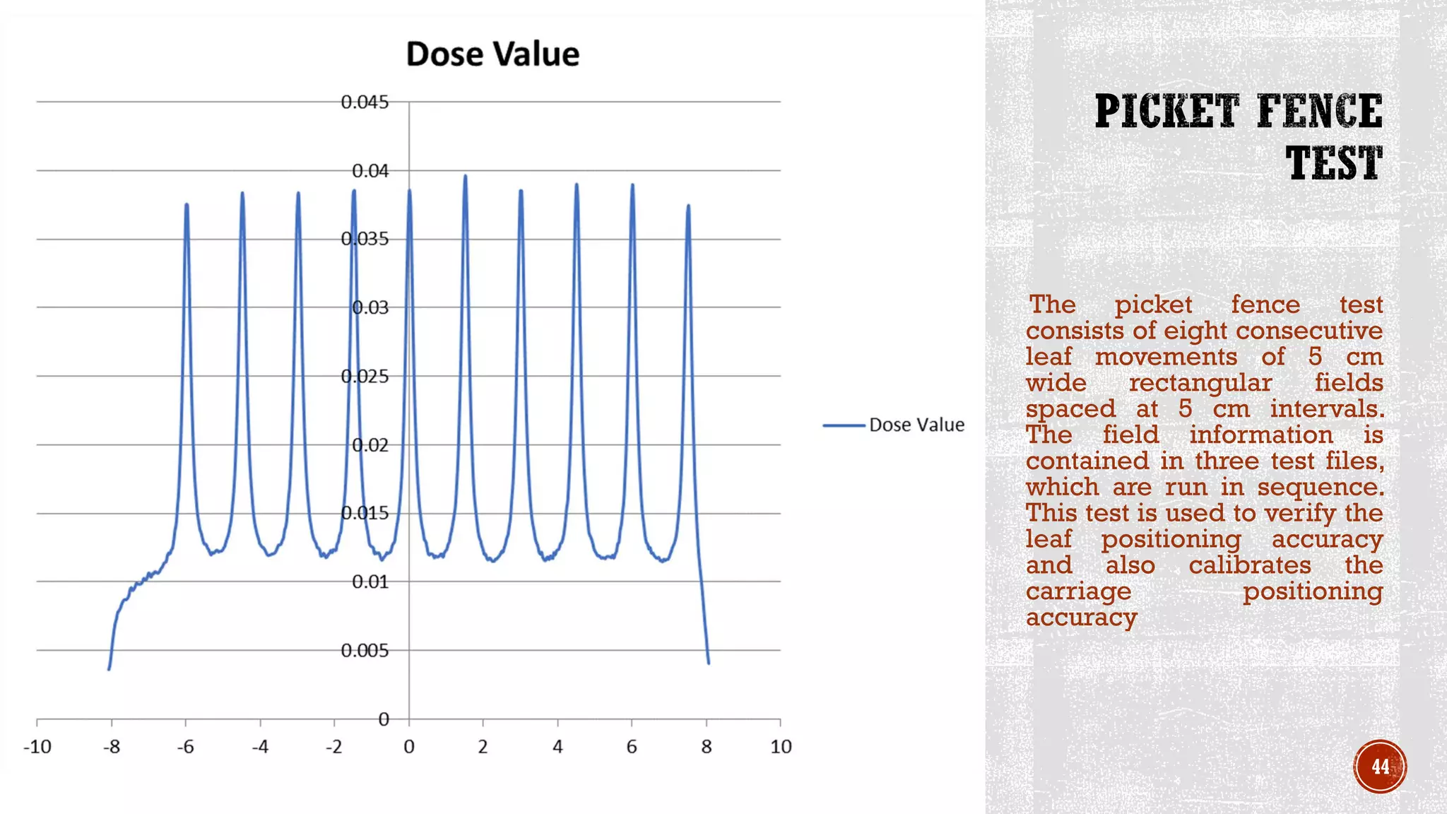
The document provides details about the acceptance testing and commissioning of a new TrueBeam linear accelerator installed at the facility. Some key details include: - The machine was installed in an existing bunker previously occupied by a Siemens Primus Plus with additional shielding added. - Acceptance testing verifies a small subset of beam data based on manufacturer guidelines to check specifications, while commissioning involves comprehensive beam measurements and treatment planning system configuration. - Beam data measurements included depth doses, profiles, output, symmetry, flatness, and other dosimetric parameters which were analyzed and entered into the treatment planning system. - Electron and photon beam energies and characteristics were evaluated to ensure they met tolerance limits. Other