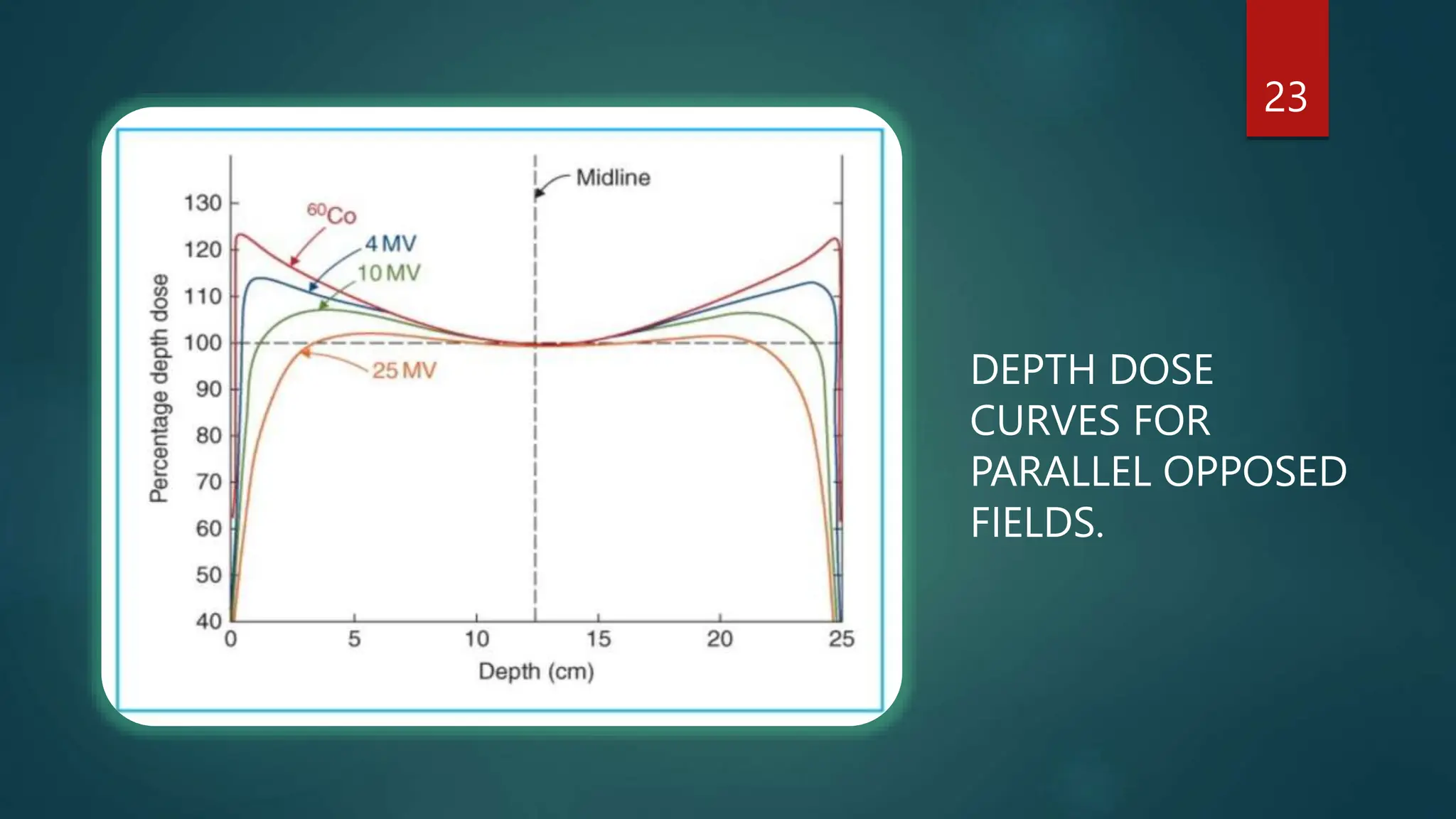
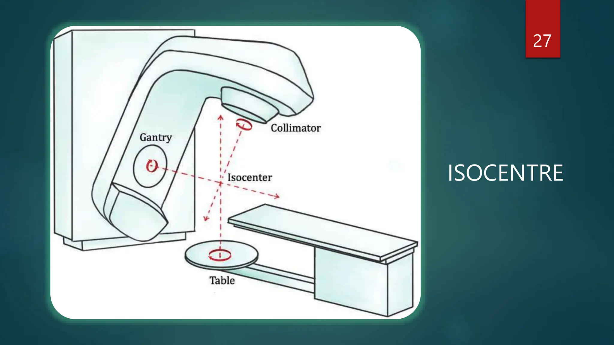
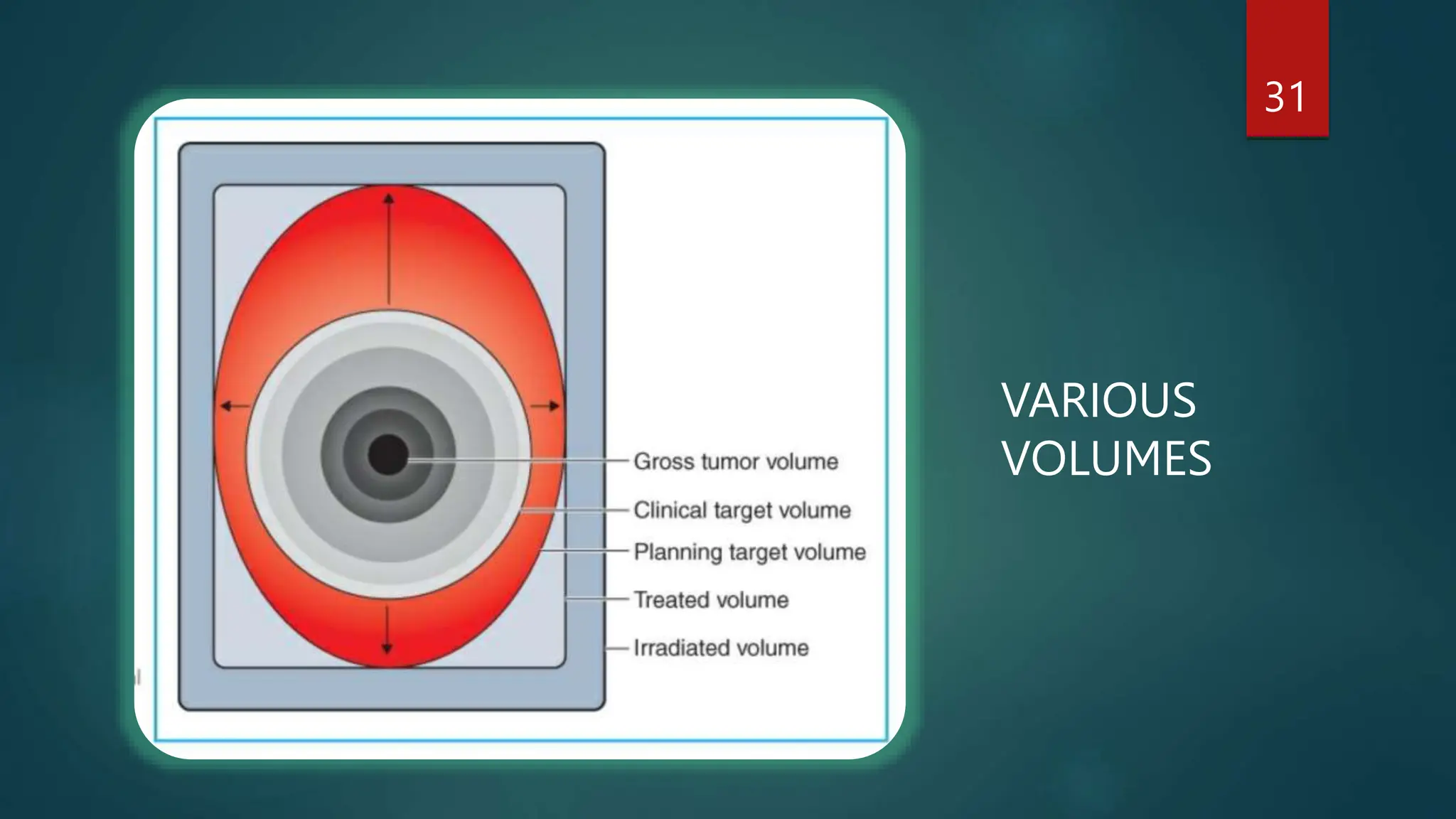
ISODOSE DISTRIBUTION
PRESENTER- ABHISHEK MEWARA
MODERATOR- MR. RATTAN SINGH
DATED- 13.1.2024
1
OVERVIEW
 ISODOSE CHARTS/ CURVES
 MEASURMENT OF ISODOSE CURVES
 PARAMETERS OF ISODOSE CURVES
 WEDGE FILTERS
 COMBINATION OF RADIATION FIELDS
 ISOCENTRE
 VARIOUS VOLUMES
2
1. ISODOSE CHART
 They are basically lines passing through points of equal dose in the
body.
 Used to characterize a radiation beam that produces a dose
distribution in a three dimensional volume.
 Usually drawn at regular intervals of absorbed dose and expressed
as a percentage of the dose at a reference point.
 They represents the variation in dose as a function of depth and
transverse distance from the central axis of the radiation beam.
3
 The dose at the surface is greatest, and it gradually decreases
with depth. It is shown by SSD curve, or source to surface
distance curve.
 Similarly, the dose at any depth is greatest on the central axis of
the beam and gradually decreases toward the edges of the
beam, as a function of lateral distance from the beam axis. And
this is shown by SSA curve, or source to axis distance curve.
4
5
A: SOURCE TO SURFACE
DISTANCE (SSD) TYPE
B: SOURCE TO AXIS DISTANCE
(SAD) TYPE
6
DOSE PROFILE AT DEPTH SHOWING VARIATION OF DOSE ACROSS THE FIELD.
7
CROSS-SECTIONAL ISODOSE DISTRIBUTION IN A PLANE
PERPENDICULAR TO THE CENTRAL AXIS OF THE BEAM.
2. MEASURMENT OF ISODOSE CURVES
 Done by ion chambers, e.g. Thimble chambers.
 Kept inside a water seal, aka the ‘phantoms’.
 Water is the medium of choice in the phantoms.
8
9
A WATER PHANTOM
10
WATER PHANTOM THIMBLE CHAMBER
3. PARAMETERS OF ISODOSE CURVES
1. BEAM QUALITY-
 The depth of a given isodose curve increases with beam quality.
 Greater the beam quality or intensity, greater is the depth of the
curve.
 Greater lateral scatter is associated with very low-energy beams,
which causes the isodose curves outside the field to bulge out.
 The absorbed dose in the medium outside the primary beam is
greater for low-energy beams than for higher energy beams.
11
2. BEAM COLLIMATION AND PENUMBRA-
 A collimator is a system designed to vary the size and shape of the
beam to meet the individual treatment requirements.
 The term penumbra, means the region, at the edge of a radiation
beam, over which the dose rate changes rapidly and exponentially
as a function of distance from the beam axis.
12
PENUMBRA
3. COLLIMATION AND FLATTENING FILTER-
 The collimator blocks or multi leaf collimators or the flattening filters
are devices that give shape and size to the beam.
 The flattening filter has the greatest influence in determining the
shape of the isodose curves.
 Without this filter, the isodose curves will be conical in shape, showing
markedly increased intensity along the central axis and a rapid
reduction transversely.
 The function of the flattening filter is to make the beam intensity
distribution relatively uniform across the field, i.e. to make the curve
or the distribution flat.
 We need to achieve flatness to within ±3% of the central axis dose
value at a 10-cm depth, for it to be statistically correct.
13
4. FLATTENING FILTER FREE LINAC’S-
 Used in LinAc designed only to deliver small fields, such as for
radiosurgery treatments which may not need a flattening filter to
produce a beam that is sufficiently uniform.
5. FIELD SIZE-
 Adequate dosimetric coverage of the tumor requires a
determination of appropriate field size.
14
4. WEDGE FILTERS
 A wedge filter is basically an absorber that causes a progressive
decrease in the intensity across the beam, resulting in a tilt of the
isodose curves from their normal positions.
 The isodose curves are tilted toward the thin end, and the degree of
tilt depends on the slope of the wedge filter.
 There are two classes of wedge filters:
a) Physical wedge filters
b) Non physical/ dynamic wedge filters.
15
 Wedges are made of different materials, most common being
copper and lead.
 Available for different angles, e.g. 15º, 30º, 45º, 60º, etc.
16
17
ISODOSE CURVES FOR A WEDGE FILTER.
A wedge filter
18
WEDGES
15º 30º
45º
60º
 Important points to know about wedge
filters-
1. WEDGE ISODOSE ANGLE-
 The term wedge isodose angle or
wedge angle, refers to the angle
through which an isodose curve is
tilted at the central ray of a beam at a
specified depth.
19
2. WEDGE TRANSMISSION FACTOR-
 The presence of a wedge filter decreases the output of the
machine, which must be taken into account in treatment
calculations.
 This error is corrected by the wedge transmission factor, defined
as the ratio of doses with and without the wedge, at a point
along the central axis of the beam.
20
5. COMBINATION OF RADIATION FIELDS-
A. PARALLEL OPPOSED FIELDS -:
 The pair of fields are directed along the same axis from opposite
sides of the treatment volume.
21
22
ISODOSE CURVE FOR A PAIR
OF PARALLEL OPPOSED
FIELDS.
23
DEPTH DOSE
CURVES FOR
PARALLEL OPPOSED
FIELDS.
B. MULTIPLE FIELDS -:
 It is essential to deliver maximum dose to the tumor and minimum
dose to the surrounding tissues.
 In addition, dose uniformity within the tumor volume is also
important.
 Some of the strategies useful in achieving these goals are -
(a) Size of the fields
(b) Number of fields or portals
(c) Beam direction
(d) Beam energy
(e) Beam modifiers such as wedge filters
24
25
MULTIPLE FIELD ARRANGEMENTS, ALWAYS DIRECTED AT THE TUMOR.
A. @ Right angles.
B. @120º.
C. 3 fields.
6. ISOCENTer
 Most modern machines are constructed so that the source of
radiation can rotate about a horizontal axis.
 The gantry, the table, and the collimator of the machine are
capable of rotating around each other.
 The gantry moves around in horizontal plane, and the collimator
axis moves in the vertical plane.
 The isocenter is the point of intersection of the collimator axis, the
gantry axis, and the table axis of rotation.
 For LinAc, it is100cm, and for cobalt, it is 80cm.
26
27
ISOCENTRE
7. VARIOUS VOLUMES
A. Gross tumor volume
B. Clinical tumor volume
C. Planning tumor volume
D. Treated tumor volume
E. Irradiated tumor volume
28
1. GROSS TUMOR VOLUME-
 The gross tumor volume (GTV) is the gross demonstrable/ visible/
palpable extent and location of the tumor.
 It may consist of primary tumor, metastatic lymphadenopathy, or other
metastases.
2. CLINICAL TARGET VOLUME-
 The clinical target volume (CTV) consists of the demonstrated tumor,
and any other tissue with presumed tumor, including the subclinical
disease.
 It represents therefore the true extent and location of the tumor.
 Delineation of CTV assumes that there are no tumor cells outside this
volume.
29
3. PLANNING TARGET VOLUME-
 The margin around CTV in any direction must be large enough to compensate
for internal movements as well as patient motion.
 The volume that includes this is known as the PTV.
4. TREATED VOLUME-
 Additional margins must be provided around the target volume to allow for
limitations of the treatment technique.
 This denotes TV.
5. IRRADIATED VOLUME-
 The volume of tissue receiving a significant dose (e.g., ≥50% of the specified
target dose) is called the irradiated volume.
30
31
VARIOUS
VOLUMES
32
Various Volumes and Margins.
REFERENCE-
KHAN’S TEXTBOOK OF
RADIOPHYSICS
33
THANK YOU,
AND HAVE A NICE DAY!
34

4. Isodose Distribution In Radiation Oncology .pptx

  • 1.
    ISODOSE DISTRIBUTION PRESENTER- ABHISHEKMEWARA MODERATOR- MR. RATTAN SINGH DATED- 13.1.2024 1
  • 2.
    OVERVIEW  ISODOSE CHARTS/CURVES  MEASURMENT OF ISODOSE CURVES  PARAMETERS OF ISODOSE CURVES  WEDGE FILTERS  COMBINATION OF RADIATION FIELDS  ISOCENTRE  VARIOUS VOLUMES 2
  • 3.
    1. ISODOSE CHART They are basically lines passing through points of equal dose in the body.  Used to characterize a radiation beam that produces a dose distribution in a three dimensional volume.  Usually drawn at regular intervals of absorbed dose and expressed as a percentage of the dose at a reference point.  They represents the variation in dose as a function of depth and transverse distance from the central axis of the radiation beam. 3
  • 4.
     The doseat the surface is greatest, and it gradually decreases with depth. It is shown by SSD curve, or source to surface distance curve.  Similarly, the dose at any depth is greatest on the central axis of the beam and gradually decreases toward the edges of the beam, as a function of lateral distance from the beam axis. And this is shown by SSA curve, or source to axis distance curve. 4
  • 5.
    5 A: SOURCE TOSURFACE DISTANCE (SSD) TYPE B: SOURCE TO AXIS DISTANCE (SAD) TYPE
  • 6.
    6 DOSE PROFILE ATDEPTH SHOWING VARIATION OF DOSE ACROSS THE FIELD.
  • 7.
    7 CROSS-SECTIONAL ISODOSE DISTRIBUTIONIN A PLANE PERPENDICULAR TO THE CENTRAL AXIS OF THE BEAM.
  • 8.
    2. MEASURMENT OFISODOSE CURVES  Done by ion chambers, e.g. Thimble chambers.  Kept inside a water seal, aka the ‘phantoms’.  Water is the medium of choice in the phantoms. 8
  • 9.
  • 10.
  • 11.
    3. PARAMETERS OFISODOSE CURVES 1. BEAM QUALITY-  The depth of a given isodose curve increases with beam quality.  Greater the beam quality or intensity, greater is the depth of the curve.  Greater lateral scatter is associated with very low-energy beams, which causes the isodose curves outside the field to bulge out.  The absorbed dose in the medium outside the primary beam is greater for low-energy beams than for higher energy beams. 11
  • 12.
    2. BEAM COLLIMATIONAND PENUMBRA-  A collimator is a system designed to vary the size and shape of the beam to meet the individual treatment requirements.  The term penumbra, means the region, at the edge of a radiation beam, over which the dose rate changes rapidly and exponentially as a function of distance from the beam axis. 12 PENUMBRA
  • 13.
    3. COLLIMATION ANDFLATTENING FILTER-  The collimator blocks or multi leaf collimators or the flattening filters are devices that give shape and size to the beam.  The flattening filter has the greatest influence in determining the shape of the isodose curves.  Without this filter, the isodose curves will be conical in shape, showing markedly increased intensity along the central axis and a rapid reduction transversely.  The function of the flattening filter is to make the beam intensity distribution relatively uniform across the field, i.e. to make the curve or the distribution flat.  We need to achieve flatness to within ±3% of the central axis dose value at a 10-cm depth, for it to be statistically correct. 13
  • 14.
    4. FLATTENING FILTERFREE LINAC’S-  Used in LinAc designed only to deliver small fields, such as for radiosurgery treatments which may not need a flattening filter to produce a beam that is sufficiently uniform. 5. FIELD SIZE-  Adequate dosimetric coverage of the tumor requires a determination of appropriate field size. 14
  • 15.
    4. WEDGE FILTERS A wedge filter is basically an absorber that causes a progressive decrease in the intensity across the beam, resulting in a tilt of the isodose curves from their normal positions.  The isodose curves are tilted toward the thin end, and the degree of tilt depends on the slope of the wedge filter.  There are two classes of wedge filters: a) Physical wedge filters b) Non physical/ dynamic wedge filters. 15
  • 16.
     Wedges aremade of different materials, most common being copper and lead.  Available for different angles, e.g. 15º, 30º, 45º, 60º, etc. 16
  • 17.
    17 ISODOSE CURVES FORA WEDGE FILTER. A wedge filter
  • 18.
  • 19.
     Important pointsto know about wedge filters- 1. WEDGE ISODOSE ANGLE-  The term wedge isodose angle or wedge angle, refers to the angle through which an isodose curve is tilted at the central ray of a beam at a specified depth. 19
  • 20.
    2. WEDGE TRANSMISSIONFACTOR-  The presence of a wedge filter decreases the output of the machine, which must be taken into account in treatment calculations.  This error is corrected by the wedge transmission factor, defined as the ratio of doses with and without the wedge, at a point along the central axis of the beam. 20
  • 21.
    5. COMBINATION OFRADIATION FIELDS- A. PARALLEL OPPOSED FIELDS -:  The pair of fields are directed along the same axis from opposite sides of the treatment volume. 21
  • 22.
    22 ISODOSE CURVE FORA PAIR OF PARALLEL OPPOSED FIELDS.
  • 23.
  • 24.
    B. MULTIPLE FIELDS-:  It is essential to deliver maximum dose to the tumor and minimum dose to the surrounding tissues.  In addition, dose uniformity within the tumor volume is also important.  Some of the strategies useful in achieving these goals are - (a) Size of the fields (b) Number of fields or portals (c) Beam direction (d) Beam energy (e) Beam modifiers such as wedge filters 24
  • 25.
    25 MULTIPLE FIELD ARRANGEMENTS,ALWAYS DIRECTED AT THE TUMOR. A. @ Right angles. B. @120º. C. 3 fields.
  • 26.
    6. ISOCENTer  Mostmodern machines are constructed so that the source of radiation can rotate about a horizontal axis.  The gantry, the table, and the collimator of the machine are capable of rotating around each other.  The gantry moves around in horizontal plane, and the collimator axis moves in the vertical plane.  The isocenter is the point of intersection of the collimator axis, the gantry axis, and the table axis of rotation.  For LinAc, it is100cm, and for cobalt, it is 80cm. 26
  • 27.
  • 28.
    7. VARIOUS VOLUMES A.Gross tumor volume B. Clinical tumor volume C. Planning tumor volume D. Treated tumor volume E. Irradiated tumor volume 28
  • 29.
    1. GROSS TUMORVOLUME-  The gross tumor volume (GTV) is the gross demonstrable/ visible/ palpable extent and location of the tumor.  It may consist of primary tumor, metastatic lymphadenopathy, or other metastases. 2. CLINICAL TARGET VOLUME-  The clinical target volume (CTV) consists of the demonstrated tumor, and any other tissue with presumed tumor, including the subclinical disease.  It represents therefore the true extent and location of the tumor.  Delineation of CTV assumes that there are no tumor cells outside this volume. 29
  • 30.
    3. PLANNING TARGETVOLUME-  The margin around CTV in any direction must be large enough to compensate for internal movements as well as patient motion.  The volume that includes this is known as the PTV. 4. TREATED VOLUME-  Additional margins must be provided around the target volume to allow for limitations of the treatment technique.  This denotes TV. 5. IRRADIATED VOLUME-  The volume of tissue receiving a significant dose (e.g., ≥50% of the specified target dose) is called the irradiated volume. 30
  • 31.
  • 32.
  • 33.
  • 34.
    THANK YOU, AND HAVEA NICE DAY! 34