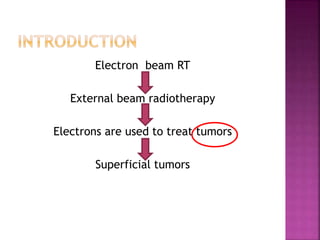
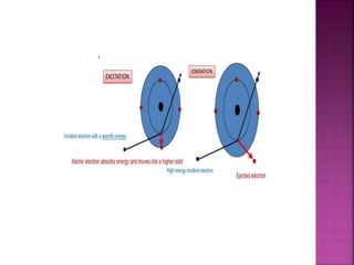
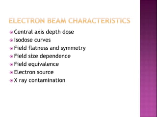
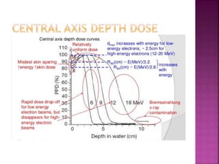
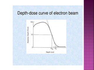
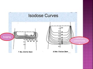
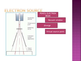
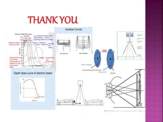
By ANKITA PANDEY
Electron beam RT
External beam radiotherapy
Electrons are used to treat tumors
Superficial tumors
 Megavoltage electron beams are used
 Clinically useful energies are between 6 to 20
MeV
 Delivers uniform dose at specific depth
 Rapid dose fall off
 Better deep normal tissue sparing
 Effective treatment for superficial tumors
 Treating various superficial diseases ( within
6cm)
 Example
1. Cancer of skin regions or total skin ( eg
mycosis fungoids)
2. Melanoma
3. Lymphoma
4. Nodal boost
5. Breast cancer
6. Total body irradiation
 Electrons interact with matter by coulombs
force interaction
 The various process of interactions are
1. Inelastic collision with atomic electrons
2. Inelastic collision with nuclei
3. Elastic collision with atomic electrons
4. Elastic collision with nuclei
 Some energy is lost
 Excitation
 ionization
 Kinetic energy is not lost although it may be
redistributed among particles emerging from
collision
When beam of electrons passes through a medium
Scattering scattering power
varies as square of
atomic no. And
Due to coulomb force inversely as square
of interaction between of K.E.
incident electrons
and nuclei
 Clinical implication
 For this reason high atomic number materials
are used in the construction of scattering foils
used for the production of clinical electron
beams in the linac
 Central axis depth dose
 Isodose curves
 Field flatness and symmetry
 Field size dependence
 Field equivalence
 Electron source
 X ray contamination
 Depth dose curve
 Rapid rise to 100%
 Rapid dose fall off
 High surface dose
 Clinically useful range 5-6cm
 As dose decreases rapidly beyond 90% dose
level, the treatment depth and required
electron energy must be chosen carefully
 Most useful treatment depth, therapeutic
range of electrons is given by the depth of 90%
of isodose curves
 The PDD increases as the energy increases
 However, percent of surface dose increases
with energy
 R90 = E/3.2
 R80 = E/2.8
 Defined as absorbed dose at any depth ‘d ‘
to the absorbed dose at fixed reference
depth along central axis of beam expressed
in percentage
 Isodose curves are the lines joining the
points of equal PDD
 The curves are usually drawn at regular
intervals of absorbed dose and expressed as
percentage of dose at a reference point.
Lateral
constrictio
n
bulging
 As an electron beam penetrates a medium,
the beam expands rapidly below the surface,
due to scattering
 Individual spread of the isodose curves varies
depending on the isodose level, energy of
the beam, field size, and beam collimation
 Uniformity of electron beam is usually
specified in a plane perpendicular to the
beam axis and at a fixed depth
uniformity index
ratio of the area where dose exceeds 90% of
its value at the central axis to the geometric
beam cross sectional area at the phantom
surface
 Because of the presence of low energy
electrons in the beam, the flatness changes
significantly with depth
 Beam symmetry compares a lateral dose
profile on one side of central axis to that on
the other
 The output and central axis depth dose are
field size dependent
 Dose increases with the field size because of
increased scatter from the collimator
PENCIL ELECTRON
BEAM
Vacuum window
diverge
Virtual source point
 At the end of the electron range
 Contributed by the bremsstrahlung
interaction of the electrons with the
collimator system and the body tissues
 X ray contamination is least with the
scanning type of accelerators because
scattering foils are not used
Electron energy X ray contamination dose
6 to 12 MeV 0.5 to 1%
12 to 15 MeV 1 to 2%
15 to 20 MeV 2 to 5%
 Single field technique
 For flat surface and homogenous tissue, dose
distribution can be found by isodose chart
 Treating area is irregular and inhomogenous
 Choice of energy and field size
 Correction of air gaps and beam obliquity
 Tissue inhomogeneity
 Use of bolus
 Problems of adjacent feilds
 Energy of beam is decided according to
1. Depth of target volume
2. Minimum target dose required
3. Dose to OARs
If there is no risk of normal organ
overdosing then beam energy is selected so
that entire tumor volume is covered by 90%
to 95% isodose curve
 Choice of field size is based on isodose
coverage of PTV
 It has been seen that there is lateral
constriction of the 80% isodose curve at
energies above 7MeV
 Thus larger field size should be selected to
cover PTV adequately
 Uneven air gaps as a result of patient
surfaces are often present
 Inverse square law corrections can be made
to the dose distribution to account for the
sloping surface
 Electron beam dose distribution can be
significantly altered in the presence of tissue
heterogeneity such as bone, lung and air
cavities
 It is difficult to determine dose distribution
in presence of such conditions
 Coefficient of equivalent thickness (CET)
Used to
1. Flatten out an irregular surface
2. Reduce the penetration of electrons in
parts of the field
3. Increase the surface dose
 Materials used as bolus
1. Paraffin wax
2. Polyestyrene
3. Lucite
4. Superstuff
5. superflab
 Special technique in which a rotational
electron beam is used to treat superficial
tumor volumes that follow curved surfaces
 Not widely used as
relatively complicated
physical characteristics are poorly
understood
 Electron energy 2 to 9MeV
 Mycosis fungoids and other cutaneous
lymphomas
 Rapid fall off in dose beyond shallow depth
 Skin lesions extending to 1cm depth can be
effectively treated without exceeding bone
marrow tolerance
 Translational techniques
 Large field technique
 Useful range of electrons are 6 to 20 MeV
 Electrons interact with matter by elastic or
inelastic collision
 Energy of electron is specified by most
probable energy at the surface
 Modest skin sparing effect
 Percent surface dose increases with
increasing energy
 Electron arc therapy is feasible for tumors
along curved surfaces
Electron beam radiotherapy

Electron beam radiotherapy

  • 1.
  • 2.
    Electron beam RT Externalbeam radiotherapy Electrons are used to treat tumors Superficial tumors
  • 3.
     Megavoltage electronbeams are used  Clinically useful energies are between 6 to 20 MeV
  • 4.
     Delivers uniformdose at specific depth  Rapid dose fall off  Better deep normal tissue sparing  Effective treatment for superficial tumors
  • 5.
     Treating varioussuperficial diseases ( within 6cm)  Example 1. Cancer of skin regions or total skin ( eg mycosis fungoids) 2. Melanoma 3. Lymphoma 4. Nodal boost 5. Breast cancer 6. Total body irradiation
  • 6.
     Electrons interactwith matter by coulombs force interaction  The various process of interactions are 1. Inelastic collision with atomic electrons 2. Inelastic collision with nuclei 3. Elastic collision with atomic electrons 4. Elastic collision with nuclei
  • 7.
     Some energyis lost  Excitation  ionization
  • 9.
     Kinetic energyis not lost although it may be redistributed among particles emerging from collision
  • 10.
    When beam ofelectrons passes through a medium Scattering scattering power varies as square of atomic no. And Due to coulomb force inversely as square of interaction between of K.E. incident electrons and nuclei
  • 11.
     Clinical implication For this reason high atomic number materials are used in the construction of scattering foils used for the production of clinical electron beams in the linac
  • 12.
     Central axisdepth dose  Isodose curves  Field flatness and symmetry  Field size dependence  Field equivalence  Electron source  X ray contamination
  • 13.
     Depth dosecurve  Rapid rise to 100%  Rapid dose fall off  High surface dose  Clinically useful range 5-6cm
  • 15.
     As dosedecreases rapidly beyond 90% dose level, the treatment depth and required electron energy must be chosen carefully  Most useful treatment depth, therapeutic range of electrons is given by the depth of 90% of isodose curves  The PDD increases as the energy increases  However, percent of surface dose increases with energy
  • 16.
     R90 =E/3.2  R80 = E/2.8
  • 17.
     Defined asabsorbed dose at any depth ‘d ‘ to the absorbed dose at fixed reference depth along central axis of beam expressed in percentage
  • 19.
     Isodose curvesare the lines joining the points of equal PDD  The curves are usually drawn at regular intervals of absorbed dose and expressed as percentage of dose at a reference point.
  • 20.
  • 21.
     As anelectron beam penetrates a medium, the beam expands rapidly below the surface, due to scattering  Individual spread of the isodose curves varies depending on the isodose level, energy of the beam, field size, and beam collimation
  • 22.
     Uniformity ofelectron beam is usually specified in a plane perpendicular to the beam axis and at a fixed depth uniformity index ratio of the area where dose exceeds 90% of its value at the central axis to the geometric beam cross sectional area at the phantom surface
  • 23.
     Because ofthe presence of low energy electrons in the beam, the flatness changes significantly with depth  Beam symmetry compares a lateral dose profile on one side of central axis to that on the other
  • 24.
     The outputand central axis depth dose are field size dependent  Dose increases with the field size because of increased scatter from the collimator
  • 25.
  • 26.
     At theend of the electron range  Contributed by the bremsstrahlung interaction of the electrons with the collimator system and the body tissues  X ray contamination is least with the scanning type of accelerators because scattering foils are not used
  • 27.
    Electron energy Xray contamination dose 6 to 12 MeV 0.5 to 1% 12 to 15 MeV 1 to 2% 15 to 20 MeV 2 to 5%
  • 28.
     Single fieldtechnique  For flat surface and homogenous tissue, dose distribution can be found by isodose chart  Treating area is irregular and inhomogenous
  • 29.
     Choice ofenergy and field size  Correction of air gaps and beam obliquity  Tissue inhomogeneity  Use of bolus  Problems of adjacent feilds
  • 30.
     Energy ofbeam is decided according to 1. Depth of target volume 2. Minimum target dose required 3. Dose to OARs If there is no risk of normal organ overdosing then beam energy is selected so that entire tumor volume is covered by 90% to 95% isodose curve
  • 31.
     Choice offield size is based on isodose coverage of PTV  It has been seen that there is lateral constriction of the 80% isodose curve at energies above 7MeV  Thus larger field size should be selected to cover PTV adequately
  • 32.
     Uneven airgaps as a result of patient surfaces are often present  Inverse square law corrections can be made to the dose distribution to account for the sloping surface
  • 33.
     Electron beamdose distribution can be significantly altered in the presence of tissue heterogeneity such as bone, lung and air cavities  It is difficult to determine dose distribution in presence of such conditions  Coefficient of equivalent thickness (CET)
  • 34.
    Used to 1. Flattenout an irregular surface 2. Reduce the penetration of electrons in parts of the field 3. Increase the surface dose
  • 35.
     Materials usedas bolus 1. Paraffin wax 2. Polyestyrene 3. Lucite 4. Superstuff 5. superflab
  • 36.
     Special techniquein which a rotational electron beam is used to treat superficial tumor volumes that follow curved surfaces  Not widely used as relatively complicated physical characteristics are poorly understood
  • 37.
     Electron energy2 to 9MeV  Mycosis fungoids and other cutaneous lymphomas  Rapid fall off in dose beyond shallow depth  Skin lesions extending to 1cm depth can be effectively treated without exceeding bone marrow tolerance
  • 38.
     Translational techniques Large field technique
  • 41.
     Useful rangeof electrons are 6 to 20 MeV  Electrons interact with matter by elastic or inelastic collision  Energy of electron is specified by most probable energy at the surface  Modest skin sparing effect  Percent surface dose increases with increasing energy  Electron arc therapy is feasible for tumors along curved surfaces