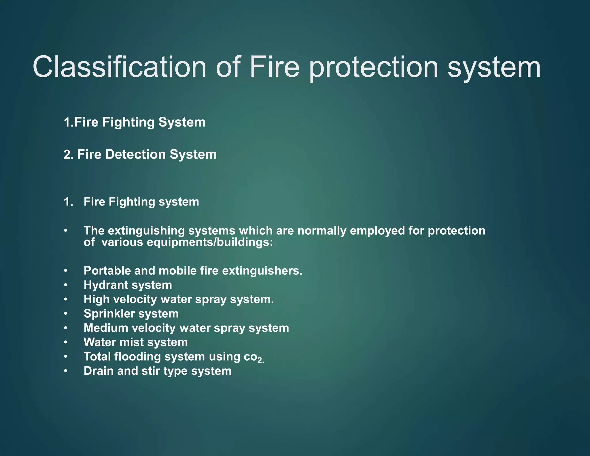
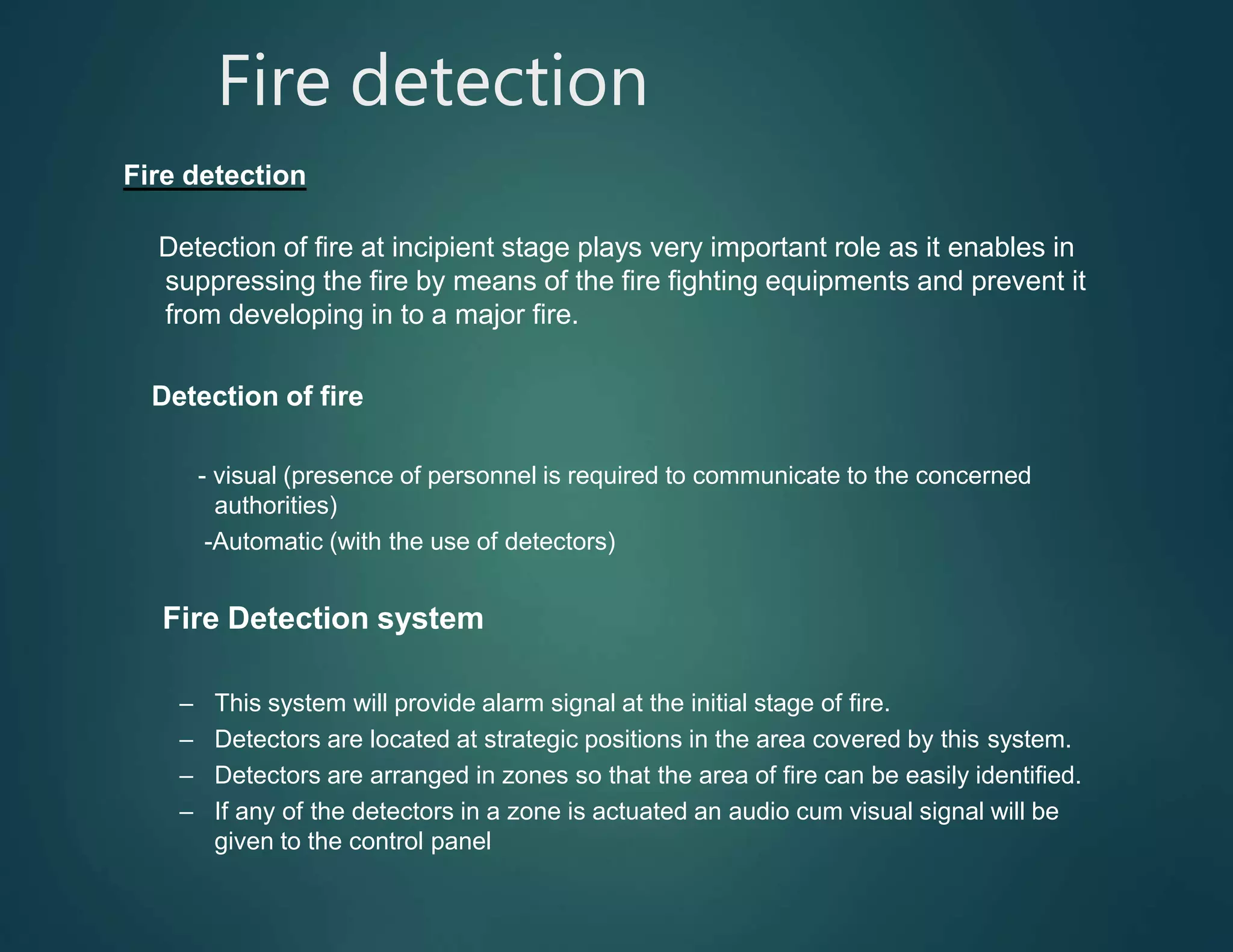
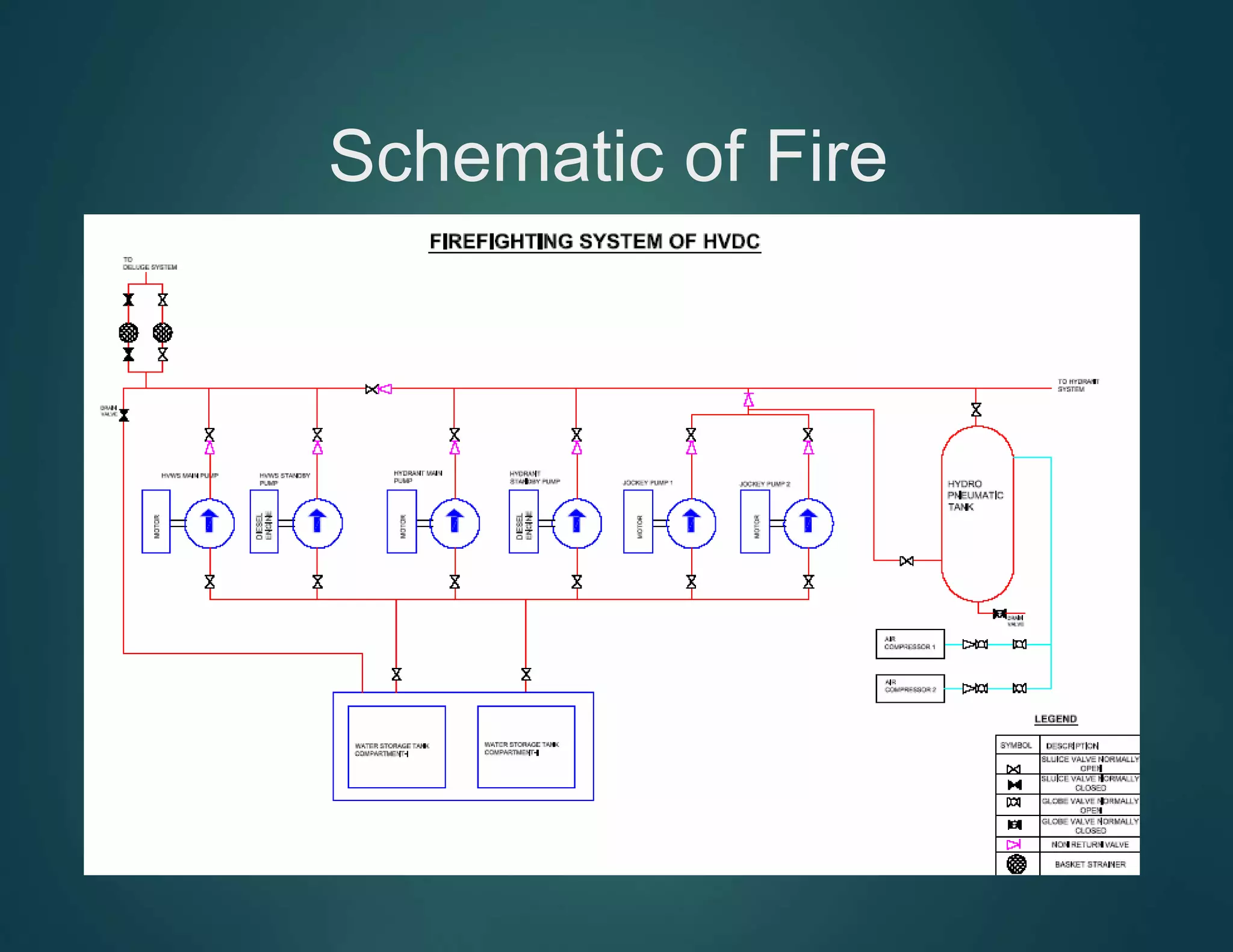
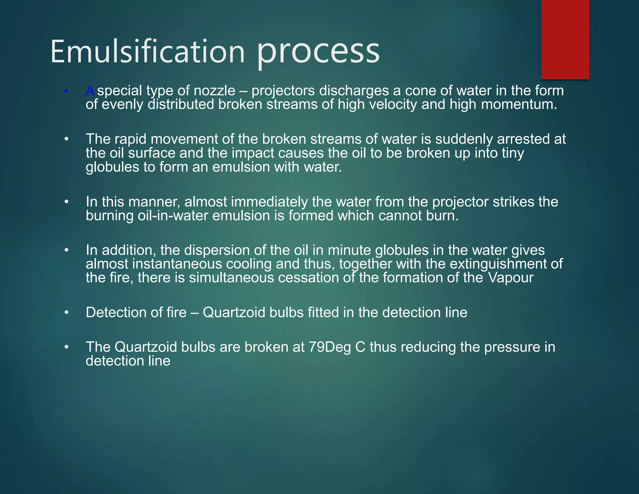
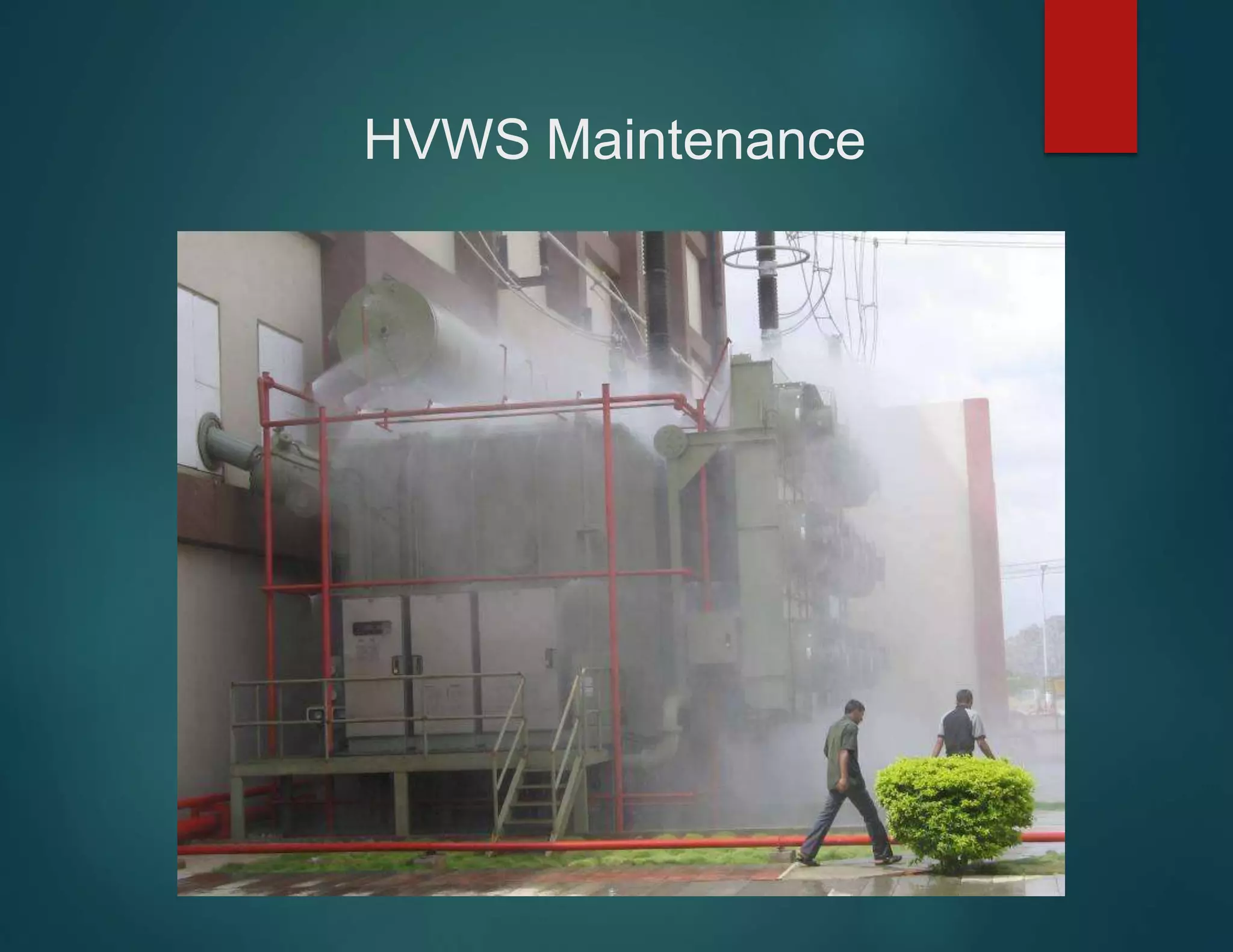
Welcome To
IMPACT FIRE & SAFETY APPLIANCES PVT. LTD
http://www.indiafireextinguisher.com
Fire Fighting System
Necessity of Fire Fighting system
• The fire fighting system in the sub station is very
essential
• Saves the equipment from damage
• Loss of life & loss of equipment can be prevented
• Regular trial operation of the system is necessary
to detect any fault /deficiency in the system.
Classification of Fire protection system
1.Fire Fighting System
2. Fire Detection System
1. Fire Fighting system
• The extinguishing systems which are normally employed for protection
of various equipments/buildings:
• Portable and mobile fire extinguishers.
• Hydrant system
• High velocity water spray system.
• Sprinkler system
• Medium velocity water spray system
• Water mist system
• Total flooding system using co2.
• Drain and stir type system
Fire detection
Fire detection
Detection of fire at incipient stage plays very important role as it enables in
suppressing the fire by means of the fire fighting equipments and prevent it
from developing in to a major fire.
Detection of fire
- visual (presence of personnel is required to communicate to the concerned
authorities)
-Automatic (with the use of detectors)
Fire Detection system
– This system will provide alarm signal at the initial stage of fire.
– Detectors are located at strategic positions in the area covered by this system.
– Detectors are arranged in zones so that the area of fire can be easily identified.
– If any of the detectors in a zone is actuated an audio cum visual signal will be
given to the control panel
Schematic of Fire
Fighting
Hydrant system
• Hose pipes along with branch pipes and nozzles are kept in post
boxes located adjacent to hydrants points
• In case of fire, these hoses are coupled to the respective hydrant
and jet of water is directed towards the seat of the fire.
• The system is automatic to the extent that whenever the pressure in
the piping network drops the beyond a preset value, signal is given
to start the hydrant pump by means of pressure switch. However
the stopping of the pump is manual.
• Water for the hydrant service is generally stored in an easily
accessible RCC reservoir. The water for the hydrant system shall
be supplied from the nearest bore wells available in the substation.
• The Hydrant system is spread in the switchyard and the auxiliary
systems
• Large pipes of dia 300mm/250mm/150mm either underneath or
above the ground runs in the yard
• Identification – post office red painted
• The pressure in the line is maintained by the air compressor in auto
mode – 7Kg/cm2
• The hydro pneumatic tank maintains the pressure and loss of water.
• Jockey pump maintains the water level in the hydro-pneumatic
tank
• Two level switches detect the water level
Hydrant system
Pumps
GENERAL REQUIREMENTS:
• Pumps shall be exclusively used for the fire fighting purposes. The
pumps used for the fire protection system are of the following types
• Electric motor driven centrifugal pumps, or
• Compression ignition engine driven centrifugal pumps or
• Vertical turbine submersible pumps.
– In all the above cases, pumps shall be automatic in action.
– Pumps shall be direct-coupled, except in the case of engine-
driven vertical turbine pumps wherein gear drive shall be used
– Belt-driven pumps shall not be used.
Pumps & Motors
• Electrical driven HVWS Pump – 410Cum/Hr Motor 125KW
• Diesel engine driven HVWS pump - 410Cum/Hr Engine 166BHP
• Electrical driven Hydrant Pump – 96Cum/Hr Motor 30KW
• Diesel engine driven HVWS pump - 96Cum/Hr Engine 57BHP
• Jockey pump – 10.8CuM/Hr Motor 7.5KW
• Air Compressor – 8Kg/Cm2 Motor 3KW
High Velocity Water (HVW) Spray System
• This system is used for the protection of transformers and reactors in the
substation.
• The High Velocity Water Spray System - for extinguishing of oil fires
• It is employed to bring about a fundamental change in the nature of the
inflammable liquid, which is converted temporarily into an emulsion which
cannot burn.
• High Velocity water spray system - network of projectors arranged around
the equipment to be protected.
• Water under pressure is directed to the projector network through a flow
control/deluge valve from a pipe network laid exclusively for the spray
system.
• The minimum running water pressure at any projector must in no instance
be below 3.5 bar.
Electrical HVWS / Diesel engine
Emulsification process
• A special type of nozzle – projectors discharges a cone of water in the form
of evenly distributed broken streams of high velocity and high momentum.
• The rapid movement of the broken streams of water is suddenly arrested at
the oil surface and the impact causes the oil to be broken up into tiny
globules to form an emulsion with water.
• In this manner, almost immediately the water from the projector strikes the
burning oil-in-water emulsion is formed which cannot burn.
• In addition, the dispersion of the oil in minute globules in the water gives
almost instantaneous cooling and thus, together with the extinguishment of
the fire, there is simultaneous cessation of the formation of the Vapour
• Detection of fire – Quartzoid bulbs fitted in the detection line
• The Quartzoid bulbs are broken at 79Deg C thus reducing the pressure in
detection line
Deluge Valve system
HVWS Maintenance
Water Spray Systems
WATER SUPPLIES:
• Water for the spray system shall be stored in any easily accessible
surface or under ground lined reservoir or above ground tanks of steel,
concrete, or masonry.
• Reservoirs/tank shall be in two independent but interconnected
compartments with a common sump for suction to facilitate cleaning and
repairs.
• Water for the systems shall be free of particles, suspended matters,etc.
and as far as possible, filtered water shall be used for the systems.
• Level indicator shall be provided for measuring the quantity of water
stored anytime.
• Water reservoir/tank shall be cleaned at least once in two years or more
frequently if necessary to prevent contamination and sedimentation.
• It is advisable to provide adequate inflow into the reservoir/tank so that the
protection can be reestablished within a short period.
Types of fire detectors
• Heat detectors
• Smoke detectors
• Flame detectors
Heat Detectors
• These are generally less sensitive than smoke detectors and
are unlikely to respond for smoldering fires.
• They are not suitable for the protection of places where small fires
can cause huge losses.e.g. Computer Rooms
• These are suitable for use in places where sufficient heat is likely to
be generated and damage caused the heat generated by fire
contributes top main hazards. E.g. Battery Rooms, Boilers etc
Smoke detectors
Two types are available
- Ionization type
- Optical Type
Ionization type :
These are based on the principle that the electric current flowing
between electrodes in an ionization chamber is reduced, when
smoke particles enter the chamber.
Optical type :
These operate by detecting the scattering or absorption of light by
smoke particles.
• Fire detection system is provided in the following areas:
• Control room with false ceiling and floor void)
• Relay room
• DCDB
• Cable vault
• Battery room
• MCC room
• Conference room
• AHU room
If false ceiling is used detectors can be provided above and below the
false ceiling.
Ionization type smoke detectors can be used in all rooms but in cable vault
a combination of ionization and photo-electric type smoke detectors are
recommended.
Smoke detectors shall be equipped with an integral LED which will
glow in the event of its operation.
Portable fire extinguishers
The different type of fire extinguishers and their application:
• Class of fire Suitable extinguisher
Class -A Fire on ordinary combustibles Gas expelled water types and
water buckets
Class-B Fires in flammable liquids, CO2 ,DCP and sand
buckets. paints, grease and solvents.
Class-C Fires in gaseous substances CO2 and DCP type.
under pressure including LPG
Class-D Fires in reactive
chemicals active metals.
Special type of DCP
and Sand buckets.
Thank You

fire fighting System

  • 1.
    Welcome To IMPACT FIRE& SAFETY APPLIANCES PVT. LTD http://www.indiafireextinguisher.com Fire Fighting System
  • 2.
    Necessity of FireFighting system • The fire fighting system in the sub station is very essential • Saves the equipment from damage • Loss of life & loss of equipment can be prevented • Regular trial operation of the system is necessary to detect any fault /deficiency in the system.
  • 3.
    Classification of Fireprotection system 1.Fire Fighting System 2. Fire Detection System 1. Fire Fighting system • The extinguishing systems which are normally employed for protection of various equipments/buildings: • Portable and mobile fire extinguishers. • Hydrant system • High velocity water spray system. • Sprinkler system • Medium velocity water spray system • Water mist system • Total flooding system using co2. • Drain and stir type system
  • 4.
    Fire detection Fire detection Detectionof fire at incipient stage plays very important role as it enables in suppressing the fire by means of the fire fighting equipments and prevent it from developing in to a major fire. Detection of fire - visual (presence of personnel is required to communicate to the concerned authorities) -Automatic (with the use of detectors) Fire Detection system – This system will provide alarm signal at the initial stage of fire. – Detectors are located at strategic positions in the area covered by this system. – Detectors are arranged in zones so that the area of fire can be easily identified. – If any of the detectors in a zone is actuated an audio cum visual signal will be given to the control panel
  • 5.
  • 6.
    Hydrant system • Hosepipes along with branch pipes and nozzles are kept in post boxes located adjacent to hydrants points • In case of fire, these hoses are coupled to the respective hydrant and jet of water is directed towards the seat of the fire. • The system is automatic to the extent that whenever the pressure in the piping network drops the beyond a preset value, signal is given to start the hydrant pump by means of pressure switch. However the stopping of the pump is manual. • Water for the hydrant service is generally stored in an easily accessible RCC reservoir. The water for the hydrant system shall be supplied from the nearest bore wells available in the substation.
  • 7.
    • The Hydrantsystem is spread in the switchyard and the auxiliary systems • Large pipes of dia 300mm/250mm/150mm either underneath or above the ground runs in the yard • Identification – post office red painted • The pressure in the line is maintained by the air compressor in auto mode – 7Kg/cm2 • The hydro pneumatic tank maintains the pressure and loss of water. • Jockey pump maintains the water level in the hydro-pneumatic tank • Two level switches detect the water level Hydrant system
  • 8.
    Pumps GENERAL REQUIREMENTS: • Pumpsshall be exclusively used for the fire fighting purposes. The pumps used for the fire protection system are of the following types • Electric motor driven centrifugal pumps, or • Compression ignition engine driven centrifugal pumps or • Vertical turbine submersible pumps. – In all the above cases, pumps shall be automatic in action. – Pumps shall be direct-coupled, except in the case of engine- driven vertical turbine pumps wherein gear drive shall be used – Belt-driven pumps shall not be used.
  • 9.
    Pumps & Motors •Electrical driven HVWS Pump – 410Cum/Hr Motor 125KW • Diesel engine driven HVWS pump - 410Cum/Hr Engine 166BHP • Electrical driven Hydrant Pump – 96Cum/Hr Motor 30KW • Diesel engine driven HVWS pump - 96Cum/Hr Engine 57BHP • Jockey pump – 10.8CuM/Hr Motor 7.5KW • Air Compressor – 8Kg/Cm2 Motor 3KW
  • 10.
    High Velocity Water(HVW) Spray System • This system is used for the protection of transformers and reactors in the substation. • The High Velocity Water Spray System - for extinguishing of oil fires • It is employed to bring about a fundamental change in the nature of the inflammable liquid, which is converted temporarily into an emulsion which cannot burn. • High Velocity water spray system - network of projectors arranged around the equipment to be protected. • Water under pressure is directed to the projector network through a flow control/deluge valve from a pipe network laid exclusively for the spray system. • The minimum running water pressure at any projector must in no instance be below 3.5 bar.
  • 11.
    Electrical HVWS /Diesel engine
  • 12.
    Emulsification process • Aspecial type of nozzle – projectors discharges a cone of water in the form of evenly distributed broken streams of high velocity and high momentum. • The rapid movement of the broken streams of water is suddenly arrested at the oil surface and the impact causes the oil to be broken up into tiny globules to form an emulsion with water. • In this manner, almost immediately the water from the projector strikes the burning oil-in-water emulsion is formed which cannot burn. • In addition, the dispersion of the oil in minute globules in the water gives almost instantaneous cooling and thus, together with the extinguishment of the fire, there is simultaneous cessation of the formation of the Vapour • Detection of fire – Quartzoid bulbs fitted in the detection line • The Quartzoid bulbs are broken at 79Deg C thus reducing the pressure in detection line
  • 13.
  • 14.
  • 15.
    Water Spray Systems WATERSUPPLIES: • Water for the spray system shall be stored in any easily accessible surface or under ground lined reservoir or above ground tanks of steel, concrete, or masonry. • Reservoirs/tank shall be in two independent but interconnected compartments with a common sump for suction to facilitate cleaning and repairs. • Water for the systems shall be free of particles, suspended matters,etc. and as far as possible, filtered water shall be used for the systems. • Level indicator shall be provided for measuring the quantity of water stored anytime. • Water reservoir/tank shall be cleaned at least once in two years or more frequently if necessary to prevent contamination and sedimentation. • It is advisable to provide adequate inflow into the reservoir/tank so that the protection can be reestablished within a short period.
  • 16.
    Types of firedetectors • Heat detectors • Smoke detectors • Flame detectors Heat Detectors • These are generally less sensitive than smoke detectors and are unlikely to respond for smoldering fires. • They are not suitable for the protection of places where small fires can cause huge losses.e.g. Computer Rooms • These are suitable for use in places where sufficient heat is likely to be generated and damage caused the heat generated by fire contributes top main hazards. E.g. Battery Rooms, Boilers etc
  • 17.
    Smoke detectors Two typesare available - Ionization type - Optical Type Ionization type : These are based on the principle that the electric current flowing between electrodes in an ionization chamber is reduced, when smoke particles enter the chamber. Optical type : These operate by detecting the scattering or absorption of light by smoke particles.
  • 18.
    • Fire detectionsystem is provided in the following areas: • Control room with false ceiling and floor void) • Relay room • DCDB • Cable vault • Battery room • MCC room • Conference room • AHU room If false ceiling is used detectors can be provided above and below the false ceiling. Ionization type smoke detectors can be used in all rooms but in cable vault a combination of ionization and photo-electric type smoke detectors are recommended. Smoke detectors shall be equipped with an integral LED which will glow in the event of its operation.
  • 19.
    Portable fire extinguishers Thedifferent type of fire extinguishers and their application: • Class of fire Suitable extinguisher Class -A Fire on ordinary combustibles Gas expelled water types and water buckets Class-B Fires in flammable liquids, CO2 ,DCP and sand buckets. paints, grease and solvents. Class-C Fires in gaseous substances CO2 and DCP type. under pressure including LPG Class-D Fires in reactive chemicals active metals. Special type of DCP and Sand buckets.
  • 20.