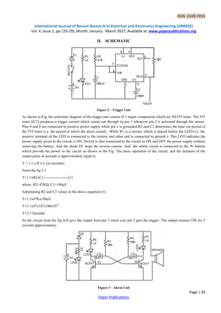
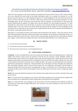
This document describes the design and implementation of a simple touch-sensitive security system. The system uses a NE555 timer circuit as a trigger unit to activate an alarm unit when the touch plate is touched. The alarm unit uses an astable multivibrator circuit with two transistors to blink LEDs and sound a buzzer in an alternating pattern. The system was tested and found to reliably detect unauthorized touches and sound the alarm as intended. The goal was to develop an affordable, reliable security system, which was achieved with this simple circuitry using readily available components.
![ISSN 2349-7815
International Journal of Recent Research in Electrical and Electronics Engineering (IJRREEE)
Vol. 4, Issue 1, pp: (25-29), Month: January - March 2017, Available at: www.paperpublications.org
Page | 28
Paper Publications
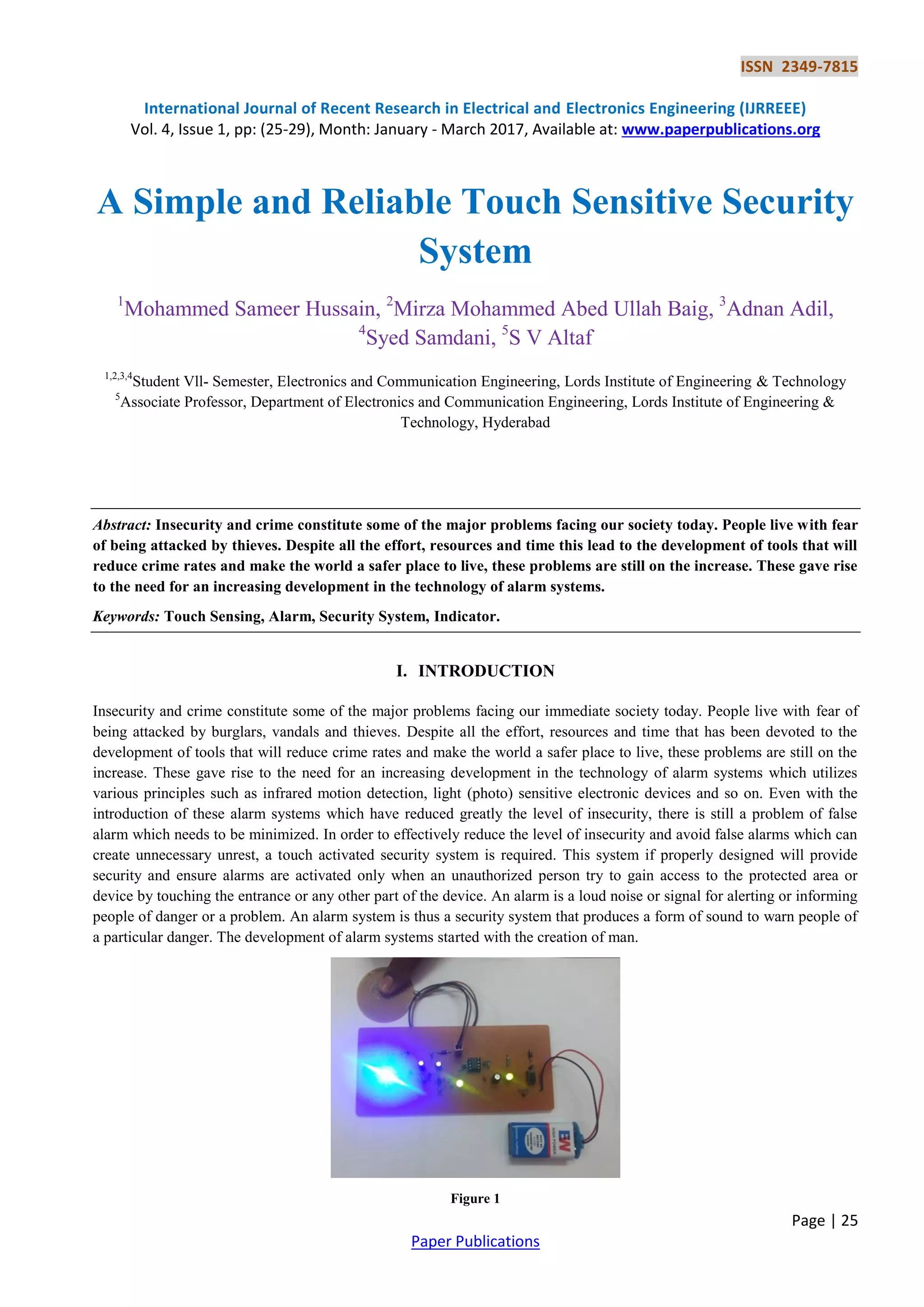
Step 3: Now connect the battery to the battery connector which is provided on the PCB. Then switch on the switch to give
the power supply to the circuit. the green LED starts glowing which indicates that the power supply to the circuit is
properly working. As shown in the figure
At this stage only green LED will glow to ensure the power supply.
Step 4: As the power supply is given to the circuit with 9v battery initially green led will glow to ensure the power
supply. Now touch the given touch plate to activate alarm. The Touch plate act as a trigger to the pin 2 of the 555 timer
which is in monostabel mode. By touching the touch plate alarm will activate indicating unauthorized access. As shown in
the figure 4.3
There are two LEDs at the output side which is in astabel mode using the transistors. The LED will glow one by one. This
will give a visual effect to the alarm circuit. So this is how the circuit look like after making on PCB board. And we get the
output.
ACKNOWLEDGEMENT
We thank the capable faculty of LORDS INSTITUTE OF ENGINEERING AND TECHNOLOGY for providing us with
an opportunity to conduct project work in college.
We are also thankful to Mr.S.V.ALTAF, ASSOCIATE PROF internal guide for his valuable academic guidance and
support.
We whole heartedly thank all staff members of Department of Electronics and Communication Engineering of LORDS
INSTITUTE OF ENGINEERING AND TECHNOLOGY for their support and encouragement related to our project work.
Lastly, we thank all those who helped us directly and indirectly with this project work which turned out to be very
successful, and we finally thank our beloved parents and family for their extreme support throughout the project.
REFERENCES
[1] Linear Integrated Circuits--D. Roy Chowdhury, New Age International (p) Ltd, 3rd
Ed., 2008.
[2] Linear Integrated Circuits-- k. Lal Kishore- Pearson, 2008.
[3] Electrical Engineering and Electronic--V.K Mehta, Rohit Mehta](https://image.slidesharecdn.com/asimpleandreliabletouchsensitive-170624061622/85/A-Simple-and-Reliable-Touch-Sensitive-Security-System-4-320.jpg)
![ISSN 2349-7815
International Journal of Recent Research in Electrical and Electronics Engineering (IJRREEE)
Vol. 4, Issue 1, pp: (25-29), Month: January - March 2017, Available at: www.paperpublications.org
Page | 29
Paper Publications
[4] www.electroniccircuitsforu.com
[5] www.extremecircuits.com
[6] www.mycircuits.com
[7] www.buildcircuits.com
[8] www.electronicshub.org
AUTHORS PROFILE:
Mr. Mohammed Sameer Hussain Pursuing B-Tech in Electronics and Communication Engineering from
Lords Institute of Engineering and Technology, Hyderabad.
Mr. Mirza Mohammed Abed Ullah Baig Pursuing B-Tech in Electronics and Communication Engineering
from Lords Institute of Engineering and Technology, Hyderabad.
Mr.Adnan Adil Pursuing B-Tech in Electronics and Communication Engineering from Lords Institute of
Engineering and Technology, Hyderabad.
Syed Samdani Pursuing B-Tech in Electronics and Communication Engineering from Lords Institute of
Engineering and Technology,Hyderabad.
Mr. S V Altaf Assoc professor in ECE department at Lords Institute of Engineering and Technology has 27
years of Industrial experience in the field of Embedded Systems along with 10 years of teaching experience in
Micro-Processors, Micro-Controllers and its applications. Also published Micro-Processors and Micro
Controllers (MP-MC), Micro-Processor and Interfacing (MPI) books.](https://image.slidesharecdn.com/asimpleandreliabletouchsensitive-170624061622/85/A-Simple-and-Reliable-Touch-Sensitive-Security-System-5-320.jpg)