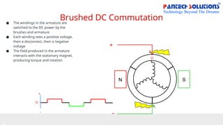
Brushed DC Commutation
●The windings in the armature are
switched to the DC power by the
brushes and armature
● Each winding sees a positive voltage,
then a disconnect, then a negative
voltage
● The field produced in the armature
interacts with the stationary magnet,
producing torque and rotation
+
-
N S
U
+
-
U
5.
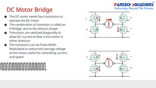
DC Motor Bridge
●The DC motor needs four transistors to
operate the DC motor
● The combination of transistor is called an
H-Bridge, due to the obvious shape
● Transistors are switched diagonally to
allow DC current to flow in the motor in
either direction
● The transistors can be Pulse Width
Modulated to reduce the average voltage
at the motor, useful for controlling current
and speed
0
1
1
1
0
0
0
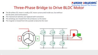
Three-Phase Bridge toDrive BLDC Motor
● The Brushless DC motor is really a DC motor constructed inside-out, but without
the Brushes and Commutators
● The mechanical switches are replaced with transistors
● The windings are moved from the armature, to the stator
● The magnet is moved from the outside to become the rotor
N S
N S
U
V
W
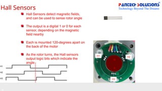
Hall Sensors
H1
H2
H3
Hall Sensorsdetect magnetic fields,
and can be used to sense rotor angle
The output is a digital 1 or 0 for each
sensor, depending on the magnetic
field nearby
Each is mounted 120-degrees apart on
the back of the motor
As the rotor turns, the Hall sensors
output logic bits which indicate the
angle
N
S
H1 H2
H3
10.
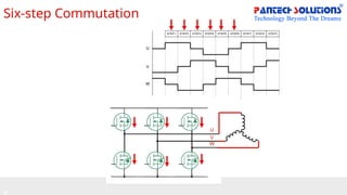
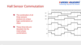
Hall Sensor Commutation
H1
H2
H3
STEP1STEP2 STEP3 STEP4 STEP5 STEP6 STEP1 STEP2 STEP3
U
V
W
The combination of all
three sensors
produce six unique
logic combinations or
steps
These three bits are
decoded into the
motor phase
combinations
11.
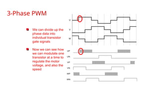
3-Phase PWM
U
V
W
We candivide up the
phase data into
individual transistor
gate signals
Now we can see how
we can modulate one
transistor at a time to
regulate the motor
voltage, and also the
speed
UP
UN
VP
VN
WP
WN
12.
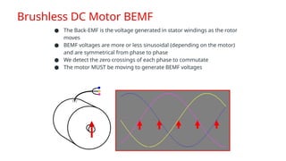
Brushless DC MotorBEMF
● The Back-EMF is the voltage generated in stator windings as the rotor
moves
● BEMF voltages are more or less sinusoidal (depending on the motor)
and are symmetrical from phase to phase
● We detect the zero crossings of each phase to commutate
● The motor MUST be moving to generate BEMF voltages
13.
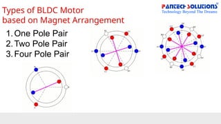
Types of BLDCMotor
based on Magnet Arrangement
1.One Pole Pair
2.Two Pole Pair
3.Four Pole Pair
14.
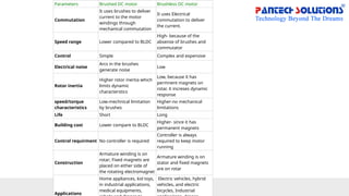
Parameters Brushed DCmotor Brushless DC motor
Commutation
It uses brushes to deliver
current to the motor
windings through
mechanical commutation
It uses Electrical
commutation to deliver
the current.
Speed range Lower compared to BLDC
High- because of the
absense of brushes and
commutator
Control Simple Complex and expensive
Electrical noise
Arcs in the brushes
generate noise
Low
Rotor inertia
Higher rotor inertia which
limits dynamic
characterstics
Low, because it has
permnent magnets on
rotar. it increses dynamic
response
speed/torque
characteristics
Low-mechnical limitation
by brushes
Higher-no mechanical
limitations
Life Short Long
Building cost Lower compare to BLDC
Higher- since it has
permanent magnets
Control requirment No controller is required
Controller is always
required to keep motor
running
Construction
Armature winding is on
rotar; Fixed magnets are
placed on either side of
the rotating electromagnet
Armature winding is on
stator and fixed magnets
are on rotar
Applications
Home appliances, kid toys,
in industrial applications,
medical equipments,
Electric vehicles, hybrid
vehicles, and electric
bicycles, Industrial
15.
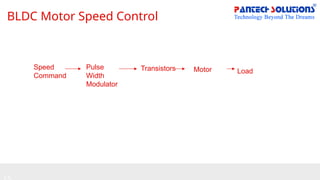
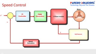
BLDC Motor SpeedControl
Speed
Command
Pulse
Width
Modulator
Transistors Motor Load
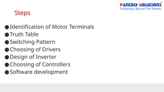
Steps
●Identification of MotorTerminals
●Truth Table
●Switching Pattern
●Choosing of Drivers
●Design of Inverter
●Choosing of Controllers
●Software development
Hall Sensor Commutation
H1
H2
H3
STEP1STEP2 STEP3 STEP4 STEP5 STEP6 STEP1 STEP2 STEP3
U
V
W
The combination of all
three sensors
produce six unique
logic combinations or
steps
These three bits are
decoded into the
motor phase
combinations
20.
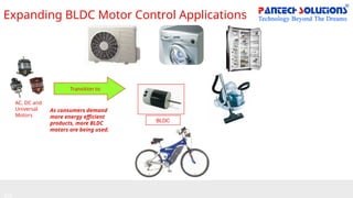
Expanding BLDC MotorControl Applications
AC, DC and
Universal
Motors
Transition to
BLDC
As consumers demand
more energy efficient
products, more BLDC
motors are being used.
21.
Project Research
● SpeedControl - Open Loop
● Speed Control - Closed Loop
● Speed Control - Closed Loop Sensorless