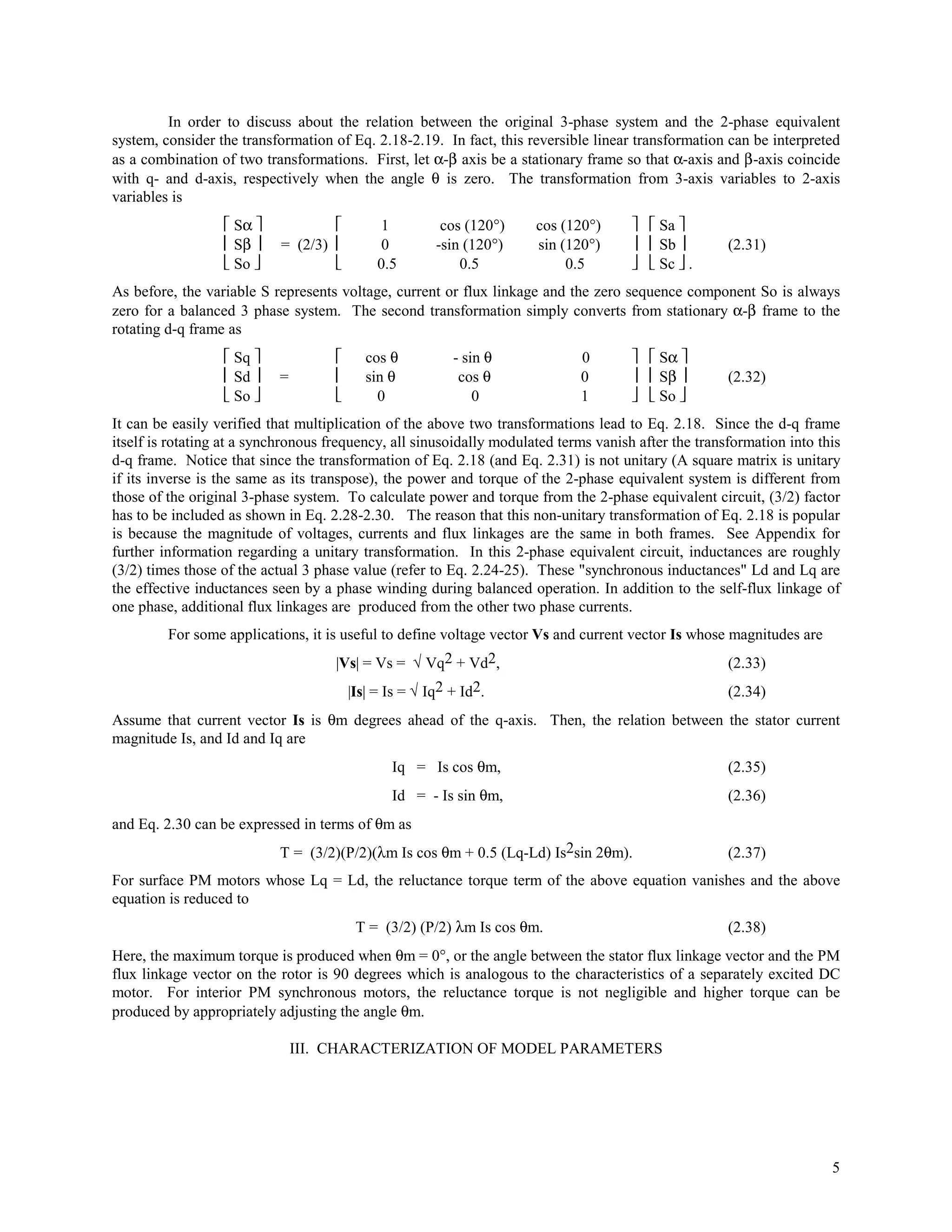
This document presents a dynamic model of a permanent magnet synchronous motor. It derives a two-phase d-q model from the three-phase model by transforming the stator variables from the stationary a-b-c frame to the rotating d-q frame. It discusses obtaining the complete set of model parameters from simple laboratory tests, as some parameters are not directly measurable and vary with operating conditions. The model is primarily for interior permanent magnet synchronous motors but can also apply to surface permanent magnet motors.
![DYNAMIC MODEL OF PM SYNCHRONOUS MOTORS
Dal Y. Ohm
Drivetech, Inc., Blacksburg, Virginia
www.drivetechinc.com
ABSTRACT: In a permanent magnet synchronous motor where inductances vary as a function of rotor
angle, the 2 phase (d-q) equivalent circuit model is commonly used for simplicity and intuition. In this
article, a two phase model for a PM synchronous motor is derived and the properties of the circuits and
variables are discussed in relation to the physical 3 phase entities. Moreover, the paper suggests
methods of obtaining complete model parameters from simple laboratory tests. Due to the lack of
developed procedures in the past, obtaining model parameters were very difficult and uncertain, because
some model parameters are not directly measurable and vary depending on the operating conditions.
Formulation is mainly for interior permanent magnet synchronous motors but can also be applied to
surface permanent magnet motors.
I. INTRODUCTION
PM synchronous motors are now very popular in a wide variety of industrial applications. A large majority
of them are constructed with the permanent magnets mounted on the periphery of the rotor core. Following [1], we
will call them as the Surface Permanent Magnet (SPM) synchronous motors. When permanent magnets are buried
inside the rotor core rather than bonded on the rotor surface, the motor not only provides mechanical ruggedness but
also opens a possibility of increasing its torque capability. By designing a rotor magnetic circuit such that the
inductance varies as a function of rotor angle, the reluctance torque can be produced in addition to the mutual
reaction torque of synchronous motors. This class of Interior PM (IPM) synchronous motors can be considered as
the reluctance synchronous motor and the PM synchronous motor combined in one unit. It is now very popular in
industrial and military applications by providing high power density and high efficiency compared to other types of
motors.
Conventionally, a 2-phase equivalent circuit model (d-q model) [2] has been used to analyze reluctance
synchronous machines. The theory is now applied in analysis of other types of motors [3-7] including PM
synchronous motors, induction motors etc. In Section II, an equivalent 2-phase circuit model of a 3-phase IPM
machines is derived in order to clarify the concept of the transformation and the relation between 3-phase quantities
and their equivalent 2-phase quantities. Although the above equivalent circuit is very popular, discussions on
obtaining parameters of the equivalent circuit for a given motor are rarely found. The main objective of the article is
to establish a method to obtain 2-phase circuit parameters from physically measured data. Throughout the article,
the following assumptions are made:
(1) Stator windings produce sinusoidal mmf distribution. Space harmonics in the air-gaps are neglected.
(2) Air-gap reluctance has a constant component as well as a sinusoidally varying component.
(3) Balanced 3 phase supply voltage is considered.
(4) Although magnetic saturation is considered, eddy current and hysteresis effects are neglected.
In addition, presence of damper windings are not considered here because they are not used in PM synchronous
machines in general. A model with short-circuited damper windings may be used to analyze eddy current effects.
Nomenclature on this article is listed in the following. More definitions may appear as appropriate during
discussion. For notational convenience, units on all angles are in degrees.
P: number of poles of the motor.
Ia, Ib, Ic: phase a, b, c instantaneous stator current.
Va, Vb, Vc: phase a, b, c instantaneous stator voltage.
Id, Iq: d- and q- axis components of stator current](https://image.slidesharecdn.com/dynamicmodelofpmsmlqandla-110407045301-phpapp02/75/Dynamic-model-of-pmsm-lq-and-la-1-2048.jpg)
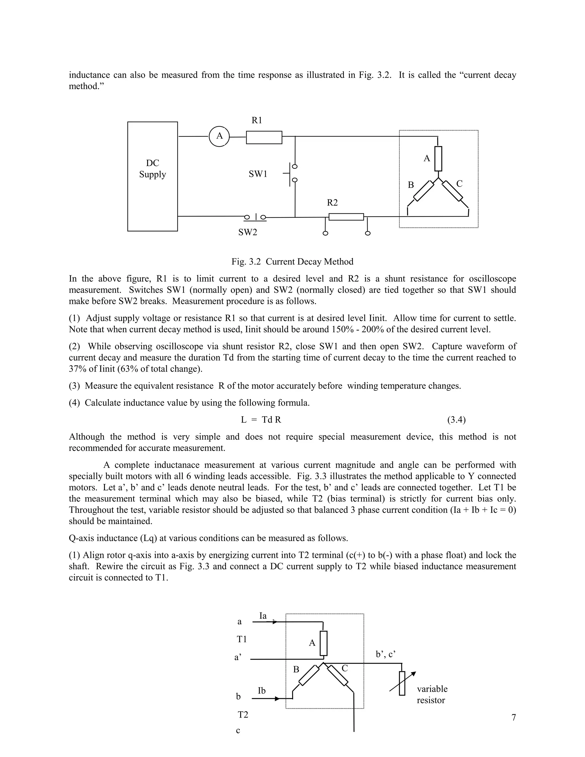
![λma = λm cos θ (2.13)
λmb = λm cos (θ - 120) (2.14)
λmc = λm cos (θ + 120) (2.15)
For this model, input power Pi can be represented as
Pi = Va Ia + Vb Ib + Vc Ic (2.16)
Unfortunately, the output power Po and the output torque T = (P/2) Po/ω cannot simply be derived in this 3-phase
model. The torque can be expressed as
T = (P/6) (Lq - Ld) [ { (Ia2 - 0.5 Ib2 - 0.5 Ic2 -Ia Ib - Ia Ic + 2 Ib Ic) sin 2θ
+ (√3/2) (Ib2 + Ic2 - 2Ia Ib + 2 Ia Ic) cos 2θ} + λm { (Ia - 0.5 Ib - 0.5 Ic) cos θ
+ (√3/2) (Ib - Ic) sin θ}]. (2.17)
Refer to [6] for detailed derivation by using energy method.
b-axis
a q-axis
b c’ θ
S a-axis
N
c b’
a’
d-axis
c-axis
Fig. 2.1 PM Synchronous Motor
Now, let S represent any of the variables (current, voltage, and flux linkage) to be transformed from the a-b-
c frame to d-q frame. The transformation in matrix form is given by
Sq cos θ cos (θ - 120) cos (θ + 120) Sa
Sd = (2/3) sin θ sin (θ - 120) sin (θ + 120) Sb (2.18)
So 0.5 0.5 0.5 Sc
Here So component is called the zero sequence component, and under balanced 3-phase system this component is
always zero. Since it is a linear transformation, its inverse transformation exists and is
Sa cos θ sin θ 1 Sq
Sb = cos (θ - 120) sin (θ - 120) 1 Sd (2.19)
Sc cos(θ + 120) sin (θ + 120) 1 So
Now, by applying the transform of Eq. 2.18 to voltages, flux-linkages and currents of Eqs.2.1-2.6, we get a set of
simple equations as
Vq = Rs Iq + p λq + ω λd (2.20)
3](https://image.slidesharecdn.com/dynamicmodelofpmsmlqandla-110407045301-phpapp02/75/Dynamic-model-of-pmsm-lq-and-la-3-2048.jpg)
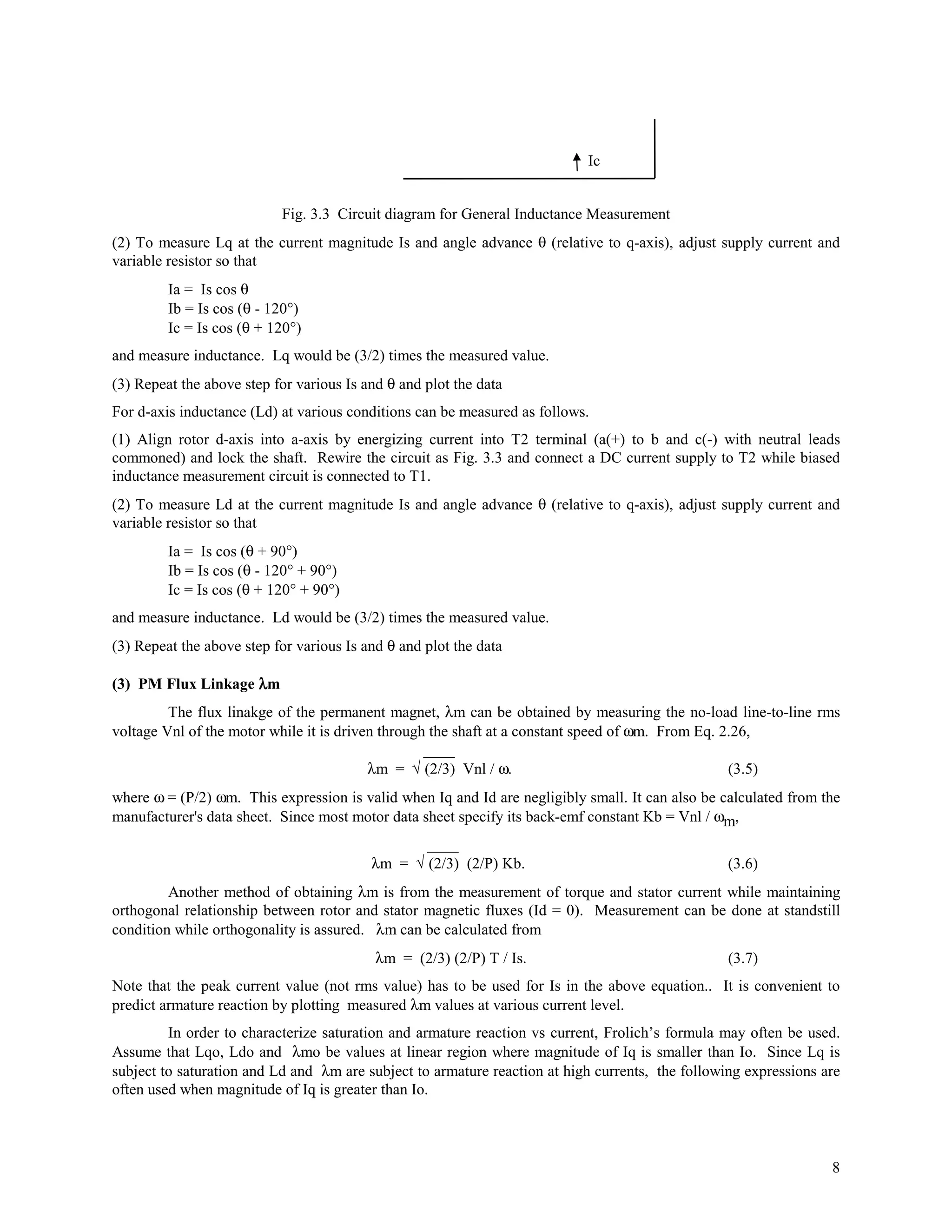
![In order to establish a 2-phase equivalent circuit of a given motor, there are four motor parameters that are
to be determined. These are stator resistance Rs, inductances Lq and Ld, and PM flux linkage λm. This portion is
adapted from [7].
(1) Stator resistance Rs
Since Rs is the resistance between line-to-neutral, Rs would be one half of the measured line-to-line
resistance. For most small to medium size PM synchronous motors, skin effect is not significant and can be safely
neglected. Winding resistance value is highly temperature-dependent. When winding resistance Ro is measured,
temperature To (°C) of the winding must be recorded and the resistance Rt at another temperature T should be
calculated using the following formula.
Rt = Ro ( K + T) / (K + To) (3.1)
where K is the constant determined by the material ( K= 234.5 for copper). Resistance value at 25°C is often used
for published data.
(2) Synchronous Inductances Lq and Ld
To measure inductance, digital RLC meter or inductance bridge is often used. These measurements give
inductance value at a small current and may not be suitable to predict characteristics of the motor. The small signal
inductance value may be lower than unsaturated inductance value since permeability of iron decreases at very low
flux densities [8]. Since inductance is also subject to saturation, we need to measure inductances at various current
level of interest. Furthermore, when motor windings are delta-connected or Y connected without neutral line for
external access, one can only access line-to-line value. Even when phase inductance value is measured, calculating
synchronous inductances based on Eq. 2.24 and 2.25 may not be accurate because we do not know the leakage
inductance. In the following, a novel method of directly measuring synchronous inductances Lq and Ld with biased
current is illustrated.
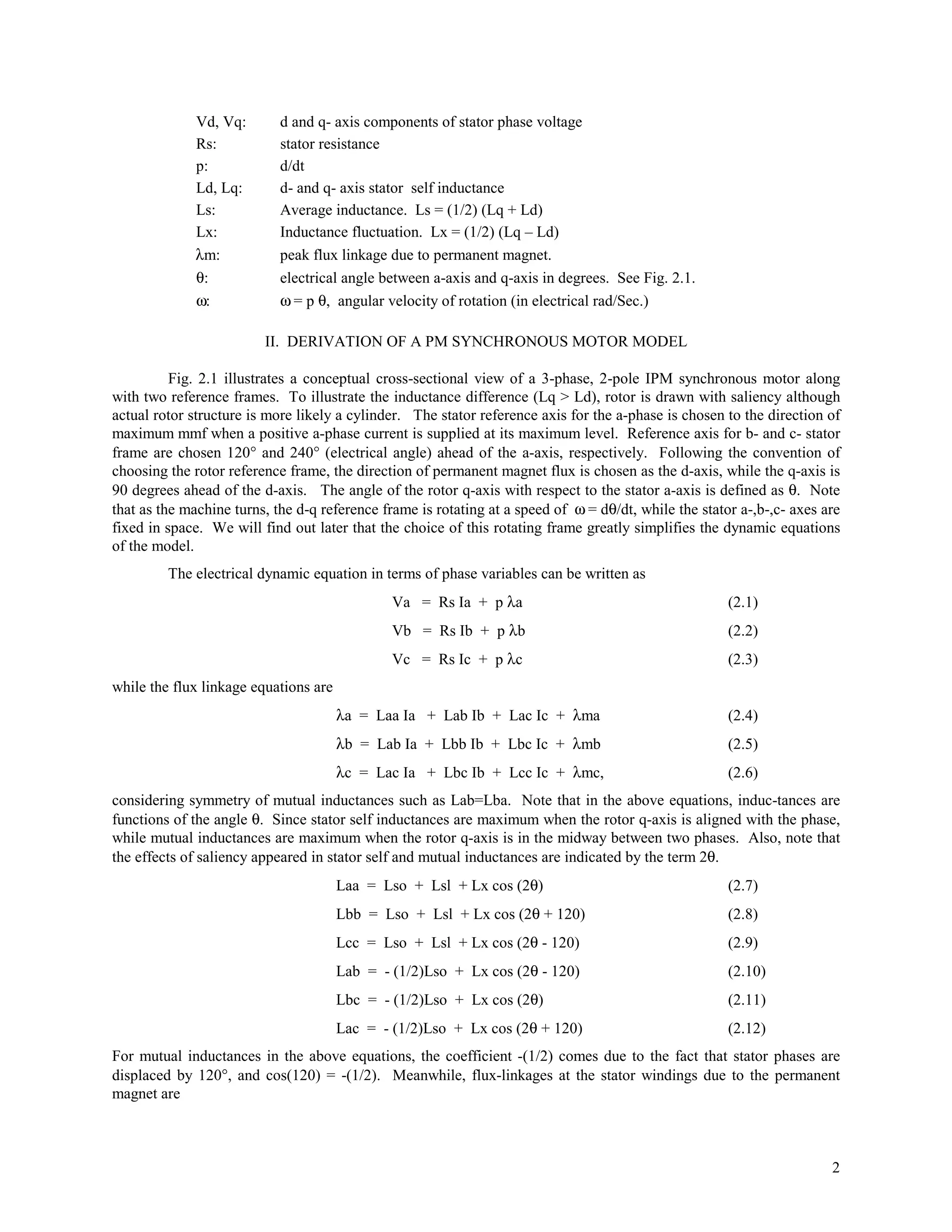
In order to measure synchronous inductance, we must maintain balanced three phase current condition.
Connection diagram of Fig. 3.1 maintains balanced 3 phase current condition at θ = 0°. When the rotor q-axis (d-
axis) is is aligned with the center of a-phase winding, Lq (Ld) can be derived from the measured equivalent
inductance L of the circuit in Fig. 3.1, depending on the rotor angle.
Lq = (2/3) L(θ = 0°), Ld = (2/3) L((θ = 90°) (3.2)
I
+
A
V
B C
-
Fig. 3.1 Connection Diagram to measure Sychronous Inductance
This relation can either be proven in a straightforward manner by using Eq. 2.1-2.15, or intuitively as follows. When
the rotor is locked at 0 degree (q-axis = a-axis) and supply voltage V is applied as in Fig. 3.1, Eq. 2.26 becomes
V = {(3/2) Rs + (3/2) Lq p} Iq (3.3)
since Vq= (2/3)V and Vd=0. Since a-phase current I is the same as Iq, and the equivalent resistance of the circuit of
Fig. 3.1 is (3/2) Rs, the equivalent inductance seen from the supply source is (3/2) Lq. Similar explanation can also
be applied to Ld when the rotor is locked at 90°.
NEMA [9] suggested two methods of measuring inductance. One is called “biased inductance bridge
method”. It describes connection diagram when traditional inductance bridge is used. Recently, new digital RLC
meters are available. Detailed procedures and circuits to measure inductances with a biased current on these meters
differ by manufacturer. Often, special optional devices in addition to the merter unit is necessary. This method, if
available, offers a simple and accurate measurement. When the biased inductance measurement is unavailable,
6](https://image.slidesharecdn.com/dynamicmodelofpmsmlqandla-110407045301-phpapp02/75/Dynamic-model-of-pmsm-lq-and-la-6-2048.jpg)
![REFERENCES
[1] T.Jahns, J.B.Kliman and T.W.Neumann, "Interior Permanent-Magnet Synchronous Motors for Adjustable-Speed
Drives," IEEE Transactions on Industry Applications, Vol.IA-22, No.4, July/August 1986.
[2] R.H.Park, "Two-reaction Theory of Synchronous Machines: Part II," AIEE Trans., Vol.52, pp.352-355, June
1933.
[3] A.E.Fitzgerald, "Electric Machinery," 5th Ed., McGraw-Hill, 1990.
[4] P.C Krause and P.Wasynczuk, "Electromechanical Motion Devices", McGraw-Hill, 1989.
[5] B.K.Bose, "Power Electronics and AC Drives," Prentice-Hall, 1986
[6] P.C.Krause, "Analysis of Electric Machinery," McGraw-Hill, 1986.
[7] D.Y.Ohm, J.W.Brown and V.B.Chava, "Modeling and Parameter Characterization of Permanent Magnet
Synchronous Motors," Proceedings of the 24th Annual Symposium of Incremental Motion Control Systems and
Devices, San Jose, pp. 81-86, June 5-8, 1995.
[8] IEEE Std. 115A - 1987. “Recommended Procedures for Obtaining Synchronous Machine Parameters by
Standstill Frequency Response Tests.”, 1987.
[9] NEMA Standard MG-7, "Motion/Position Control Motors, Controls and Feedback Devices," 1993.
(05-16-00 Word 97)
10](https://image.slidesharecdn.com/dynamicmodelofpmsmlqandla-110407045301-phpapp02/75/Dynamic-model-of-pmsm-lq-and-la-10-2048.jpg)