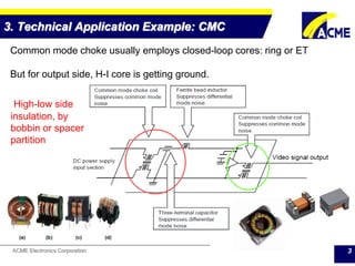
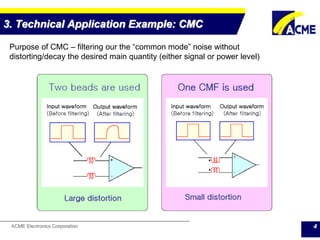
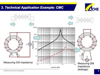
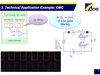
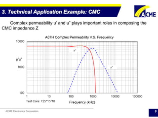
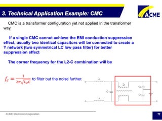
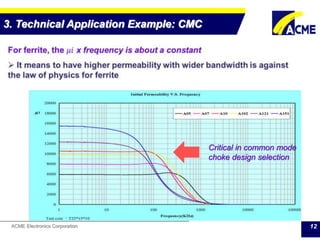
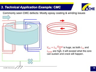
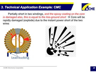
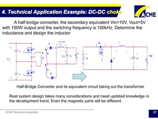
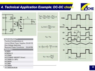
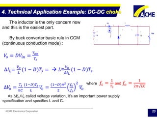
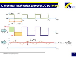
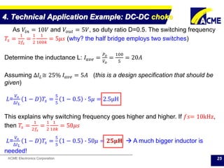
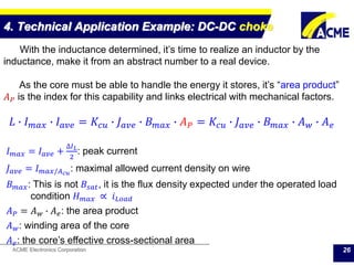
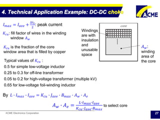
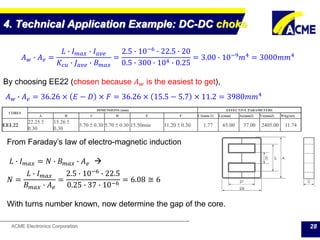
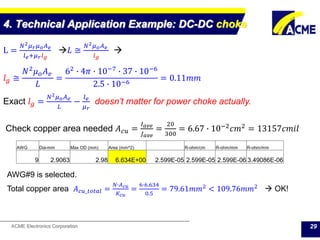
ACME Electronics Corporation 1
Ferrite Specification
&
ACME Ferrites
Technical Aspects
By Ray Lai, FAE
June 2015
With Supports of
RD & Marketing Teams
ACME Electronics Corporation
Table of Content
1. Specifications of Ferrites – Materials & Products
2. ACME ferrite road map and development trend
3. Technical Application Example: CMC
4. Technical Application Example: DC-DC choke
5. Technical Application Example: SMPS transformer
6. Appendix A: Further on ferrite specifications
7. Appendix B: (a) Fringing effect of gapped core (b)
Manipulating magnetizing curve
8. Appendix C: An analogy and differentiation on R, C, and L
and why magnetic components are so UNIQUE
Q & A
2
ACME Electronics Corporation
3. Technical Application Example: CMC
3
Common mode choke usually employs closed-loop cores: ring or ET
But for output side, H-I core is getting ground.
High-low side
insulation, by
bobbin or spacer
partition
ACME Electronics Corporation
3. Technical Application Example: CMC
4
Purpose of CMC – filtering our the “common mode” noise without
distorting/decay the desired main quantity (either signal or power level)
ACME Electronics Corporation
3. Technical Application Example: CMC
5
Ampere’s Right Hand Rule
Common mode noise has
the flux in the same direction,
the core-winding
combination will act like an
inductor (Choke)
Main circuit input/output in
different direction so the flux
canceled each other, ideally
there will be no “saturation”
possible, but, there is
leakage inductance.
ACME Electronics Corporation
3. Technical Application Example: CMC
6
Measuring CM impedance Measuring DM
impedance
(leakage)
ACME Electronics Corporation
1
L1 20
1 2
0
3
K
COUPLING=
K2
1
TX22_14_13_3E27
L1 = L2
K
COUPLING=
K1
1
TX22_14_13_3E27
L1 = L1
R1
750
2
V1
TD = 0
TF = 1u
PW = 49u
PER = 100u
V1 = -1
TR = 1u
V2 = 1
L2 20
1 2
R2
0.1
R3
0.1
3. Technical Application Example: CMC
7
Q: Why
A: 𝑍 𝐿 = 𝑗𝜔𝐿
 Low pass
filtering
ACME Electronics Corporation
3. Technical Application Example: CMC
8
1
L1 20
1 2
0
K
COUPLING=
K1
1
TX22_14_13_3E27
L1 = L1
L2 = L2
R1
750
2
V1
TD = 0
TF = 1u
PW = 49u
PER = 100u
V1 = -1
TR = 1u
V2 = 1
L2 20
1 2
R2
0.1
R3
0.1
ACME Electronics Corporation
3. Technical Application Example: CMC
9
Complex permeability u’ and u” plays important roles in composing the
CMC impedance Z
ACME Electronics Corporation
3. Technical Application Example: CMC
10
Ignoring the winding resistance (and stray capacitance), the impedance Z by
the core is
𝑍 𝐿_𝐶𝑀𝐶 = 𝑗𝜔𝐿 𝑐𝑜𝑚𝑝𝑙𝑒𝑥 = 𝑗𝜔𝑁2 𝑢 𝑜
𝐴 𝑒
𝑙 𝑒
(𝜇′ − 𝑗𝜇")
𝑍 𝐿_𝐶𝑀𝐶 = 𝜔𝑁2
𝑢 𝑜 𝜇"
𝐴 𝑒
𝑙 𝑒
+ 𝑗𝜔𝑁2
𝑢 𝑜
𝐴 𝑒
𝑙 𝑒
𝜇′
= 𝑅 𝐶𝑀𝐶 + 𝑗𝜔𝐿 𝐶𝑀𝐶
𝑍 𝐿_𝐶𝑀𝐶 = 𝜔𝑁2 𝑢 𝑜
𝐴 𝑒
𝑙 𝑒
𝜇′2
+ 𝜇"2
ACME Electronics Corporation 11
CMC is a transformer configuration yet not applied in the transformer
way.
If a single CMC cannot achieve the EMI conduction suppression
effect, usually two identical capacitors will be connected to create a
Y network (two symmetrical LC low pass filter) for better
suppression effect
The corner frequency for the L2-C combination will be
𝑓𝑐 =
1
2𝜋 𝐿2 𝐶
to filter out the noise further.
3. Technical Application Example: CMC
ACME Electronics Corporation 12
3. Technical Application Example: CMC
Critical in common mode
choke design selection
ACME Electronics Corporation 13
3. Technical Application Example: CMC
Material goal
 higher µi with improved frequency stability
 basically against physical principles
where:
fg – gyromagnetic critical frequency
γ ~0.22 ΜΗz m/A is the gyromagnetic ratio for an electron
i.e. the ratio of magnetic moment and torque
Bs – saturation flux density
μi,0– initial permeability * J. L. Snoek, Physica 14, 207, 1948
sig Bf 
3
4
)1( 0,  Snoek Limit
ACME Electronics Corporation 14
3. Technical Application Example: CMC
Characteristics of Mn-Zn and Ni-Zn Ferrite in the sense of ui vs. frequency
 All governed by Snoek limit.
ACME Electronics Corporation 15
3. Technical Application Example: CMC
For CMC, it’s not always the
higher ui the better
Note: great chance that A151
in mass production cannot
sustain such high ui through all
frequencies
Z (Ω)
Hz A07H A151
100k 1.648E+03 3.343E+03
150k 2.568E+03 4.109E+03
200k 3.517E+03 4.609E+03
500k 9.086E+03 5.938E+03
1000k 1.486E+04 5.938E+03
ACME Electronics Corporation
3. Technical Application Example: CMC
16
High Permeability Material List
Symbol Unit
Measuring Conditions High Permeability Materials
Freq. Flux den. Temp. A05 A07 A07H A10 A102 A121 A151
Initial Permeability μi ≤ 10KHz 0.25mT 25°C
5000±
25%
7000±
25%
7000 ±
25%
10000±
30%
10000±
30%
12000±
30%
15000±
30%
Realative Loss factor
tan δ/μi 10-6 10KHz
< 0.25mT 25°C
< 4 < 8 < 8 <10 <10 <10 <10
100KHz < 15 < 30 < 30 < 60 <60 <60 <110
Saturation Flux Density
Bms mT 10KHz
H=1200A/
m
25°C 440 400 440 410 380 380 400
100°C 300 200 280 210 180 180 170
Remanence
Brms mT 10KHz
H=1200A/
m
25°C 80 150 80 140 95 130 220
100°C 90 110 60 110 75 110 100
Temperature Factor of
Permeability
αF 10-6
/°C 10KHz < 0.25mT
0~20°C 0~2 -1 ~ 1 -1~1 0~1.5 -1~1 0~1.5 -1~1
20~70°C 0~2 -1 ~ 1 -1~1 -0.5~1 -1~1 -0.5~1 -1~1
Hysteresis Material
Constant
ηB 10-6
/mT 10KHz 1.5-3.0mT 25°C < 0.8 < 1.2 < 1.2 < 0.5 < 1 <0.5 <0.5
Disaccommodation
Factor
DF 10-6 10KHz < 0.25mT 25°C < 3 < 2 < 2 < 2 <2 <2 <2
Curie Temperature Tc °C 140 130 ≥ 145 130 120 110 110
Resistivity ρ Ωm 0.2 0.35 0.35 0.15 0.15 0.12 0.1
Density d g/cm3
4.85 4.9 4.9 4.9 4.9 4.9 5
Automotive
Recommended
ACME Electronics Corporation 17
3. Technical Application Example: CMC
Commonly seen CMC defects: Mostly epoxy coating & winding issues
The fluxes of 𝑖𝑙𝑜𝑎𝑑 cancel each
other in CMC configuration, so
ideally the voltage across the
CMC 𝑉𝑐𝑚 is zero,
ACME Electronics Corporation 18
3. Technical Application Example: CMC
Commonly seen CMC defects: Mostly epoxy coating & winding issues
𝑉𝑐𝑚 = 𝐿 𝑚
𝑑𝑖 𝐿𝑜𝑎𝑑
𝑑𝑡
is huge, as both 𝐿 𝑚 and
𝑖 𝐿𝑜𝑎𝑑 are high, it will exceed what the core
can sustain and crack will happen.
ACME Electronics Corporation
3. Technical Application Example: CMC
19
Partially short in one or two windings, but the epoxy coating on the
core is intact, will cause the unbalance in different mode flux (load flux)
cancellation  Core will saturate and the core will be heated up to
break point
𝑉𝑐𝑚 = 𝐿 𝑚
𝑑𝑖 𝐿𝑜𝑎𝑑
𝑑𝑡
is huge, as both 𝐿 𝑚 and
𝑖 𝐿𝑜𝑎𝑑 are high, it will exceed what the core
can sustain and crack will happen.
ACME Electronics Corporation
3. Technical Application Example: CMC
20
Partially short in two windings, and the epoxy coating on the core
is damaged also, this is equal to the line-ground short  Core will be
rapidly damaged (explode) due to the instant power short of the two
wires
ACME Electronics Corporation
4. Technical Application Example: DC-DC choke
21
Ci
Co
N2
N1
D1
Ci
D2
L
R
S1
2
1
3
S2
2
1
3
N2
Vo
>iL
-
+
-
-
+
+
Vi Vin
12
Rload
CD
LSW
2
1
3
+ +
-
-
Vo
+ -
A half-bridge converter, the secondary equivalent Vin=10V, Vout=5V
with 100W output and the switching frequency is 100kHz. Determine the
inductance and design the inductor
Half-Bridge Converter and its equivalent circuit taking out the transformer
Real system design takes many considerations and need updated knowledge in
the development trend. Even the magnetic parts will be different.
ACME Electronics Corporation
4. Technical Application Example: DC-DC choke
22
ACME Electronics Corporation
4. Technical Application Example: DC-DC choke
23
Vin
12
Rload
CD
LSW
2
1
3
+ +
-
-
Vo
+ -
The inductor is the only concern now
and this is the easiest part.
By buck converter basic rule in CCM
(continuous conduction mode) :
𝑉𝑜 = 𝐷𝑉𝑖𝑛 =
𝑇𝑜𝑛
𝑇𝑠
∆𝑉𝑜 =
𝑇𝑠
8𝐶
(1−𝐷)𝑇𝑠
𝐿
𝑉𝑜 =
(1−𝐷)𝜋2
2
𝑓𝑜
𝑓𝑠
2
𝑉𝑜
where 𝑓𝑠 =
1
𝑇𝑠
and 𝑓𝑜 =
1
2𝜋 𝐿𝐶
As ∆𝑉𝑜/𝑉𝑜 called voltage variation, it’s an important power supply
specification and specifies L and C.
∆𝐼𝐿=
𝑉𝑜
𝐿
(1 − 𝐷)𝑇𝑠 =  𝐿=
𝑉𝑜
∆𝐼 𝐿
(1 − 𝐷)𝑇𝑠
ACME Electronics Corporation
4. Technical Application Example: DC-DC choke
24
time
S1 on S1 off
Ts 2Ts
DTs (1-D)Ts
3Ts
time
ON
OFF
0
Vin-Vo
V
-Vo
time
0
A
i1
i2
1
2
∆𝐼𝐿∝ 𝐿
ACME Electronics Corporation
4. Technical Application Example: DC-DC choke
25
As 𝑉𝑖𝑛 = 10𝑉 and 𝑉𝑜𝑢𝑡 = 5𝑉, so duty ratio D=0.5. The switching frequency
𝑇𝑠 =
1
2𝑓𝑠
=
1
2
1
100𝑘
= 5𝜇𝑠 (why? the half bridge employs two switches)
Determine the inductance L: 𝐼 𝑎𝑣𝑒 =
𝑃 𝑜
𝑉𝑜
=
100
5
= 20𝐴
Assuming ∆𝐼𝐿≅ 25% 𝐼 𝑎𝑣𝑒 = 5𝐴 (this is a design specification that should be
given)
𝐿=
𝑉𝑜
∆𝐼 𝐿
1 − 𝐷 𝑇𝑠 =
5
5
1 − 0.5 ∙ 5𝜇 = 2.5μH
This explains why switching frequency goes higher and higher. If 𝑓𝑠= 10kHz,
then 𝑇𝑠 =
1
2𝑓𝑠
=
1
2
1
10𝑘
= 50𝜇𝑠
𝐿=
𝑉𝑜
∆𝐼 𝐿
1 − 𝐷 𝑇𝑠 =
5
5
1 − 0.5 ∙ 50𝜇 = 𝟐𝟓𝛍𝐇  A much bigger inductor is
needed!
ACME Electronics Corporation
4. Technical Application Example: DC-DC choke
26
With the inductance determined, it’s time to realize an inductor by the
inductance, make it from an abstract number to a real device.
As the core must be able to handle the energy it stores, it’s “area product”
𝐴 𝑃 is the index for this capability and links electrical with mechanical factors.
𝐿 ∙ 𝐼 𝑚𝑎𝑥 ∙ 𝐼 𝑎𝑣𝑒 = 𝐾𝑐𝑢 ∙ 𝐽 𝑎𝑣𝑒 ∙ 𝐵 𝑚𝑎𝑥 ∙ 𝐴 𝑃 = 𝐾𝑐𝑢 ∙ 𝐽 𝑎𝑣𝑒 ∙ 𝐵 𝑚𝑎𝑥 ∙ 𝐴 𝑤 ∙ 𝐴 𝑒
𝐼 𝑚𝑎𝑥 = 𝐼 𝑎𝑣𝑒 +
∆𝐼 𝐿
2
: peak current
𝐽 𝑎𝑣𝑒 = 𝐼 𝑚𝑎𝑥/𝐴 𝑐𝑢
: maximal allowed current density on wire
𝐵 𝑚𝑎𝑥: This is not 𝐵𝑠𝑎𝑡, it is the flux density expected under the operated load
condition 𝐻 𝑚𝑎𝑥 ∝ 𝑖 𝐿𝑜𝑎𝑑
𝐴 𝑃 = 𝐴 𝑤 ∙ 𝐴 𝑒: the area product
𝐴 𝑤: winding area of the core
𝐴 𝑒: the core’s effective cross-sectional area
ACME Electronics Corporation
4. Technical Application Example: DC-DC choke
27
𝐼 𝑚𝑎𝑥 = 𝐼 𝑎𝑣𝑒 +
∆𝐼 𝐿
2
: peak current
𝐴 𝑤:
winding
area of
the core
Windings
are with
insulation
and
unusable
space
𝐾𝑐𝑢 is the fraction of the core
window area that is filled by copper
Typical values of 𝐾𝑐𝑢 :
0.5 for simple low-voltage inductor
0.25 to 0.3 for off-line transformer
0.05 to 0.2 for high-voltage transformer (multiple kV)
0.65 for low-voltage foil-winding inductor
𝐾𝑐𝑢: fill factor of wires in the winding
window 𝐴 𝑤
By 𝐿 ∙ 𝐼 𝑚𝑎𝑥 ∙ 𝐼 𝑎𝑣𝑒 = 𝐾𝑐𝑢 ∙ 𝐽 𝑎𝑣𝑒 ∙ 𝐵 𝑚𝑎𝑥 ∙ 𝐴 𝑤 ∙ 𝐴 𝑒
𝐴 𝑤 ∙ 𝐴 𝑒 =
𝐿∙𝐼 𝑚𝑎𝑥∙𝐼 𝑎𝑣𝑒
𝐾 𝑐𝑢∙𝐽 𝑎𝑣𝑒∙𝐵 𝑚𝑎𝑥
to select core
ACME Electronics Corporation
4. Technical Application Example: DC-DC choke
28
𝐴 𝑤 ∙ 𝐴 𝑒 =
𝐿 ∙ 𝐼 𝑚𝑎𝑥 ∙ 𝐼 𝑎𝑣𝑒
𝐾𝑐𝑢 ∙ 𝐽 𝑎𝑣𝑒 ∙ 𝐵 𝑚𝑎𝑥
=
2.5 ∙ 10−6
∙ 22.5 ∙ 20
0.5 ∙ 300 ∙ 104 ∙ 0.25
= 3.00 ∙ 10−9
𝑚4
= 3000𝑚𝑚4
By choosing EE22 (chosen because 𝐴 𝑤 is the easiest to get),
𝐴 𝑤 ∙ 𝐴 𝑒 = 36.26 × 𝐸 − 𝐷 × 𝐹 = 36.26 × 15.5 − 5.7 × 11.2 = 3980𝑚𝑚4
CORES
DIMENSIONS (mm) EFFECTIVE PARAMETERS
A B C D E F C1(mm-1) Le(mm) Ae(mm2) Ve(mm3) Wt(g/set)
EEL22
22.25 ±
0.30
15.26 ±
0.30
5.70 ± 0.30 5.70 ± 0.30 15.50min 11.20 ± 0.30 1.77 65.00 37.00 2405.00 11.74
From Faraday’s law of electro-magnetic induction
𝐿 ∙ 𝐼 𝑚𝑎𝑥 = 𝑁 ∙ 𝐵 𝑚𝑎𝑥 ∙ 𝐴 𝑒 
𝑁 =
𝐿 ∙ 𝐼 𝑚𝑎𝑥
𝐵 𝑚𝑎𝑥 ∙ 𝐴 𝑒
=
2.5 ∙ 10−6
∙ 22.5
0.25 ∙ 37 ∙ 10−6
= 6.08 ≅ 6
With turns number known, now determine the gap of the core.
ACME Electronics Corporation
4. Technical Application Example: DC-DC choke
29
L =
𝑁2 𝜇 𝑟 𝜇 𝑜 𝐴 𝑒
𝑙 𝑒+𝜇 𝑟 𝑙 𝑔
𝐿 ≅
𝑁2 𝜇 𝑜 𝐴 𝑒
𝑙 𝑔

𝑙 𝑔 ≅
𝑁2 𝜇 𝑜 𝐴 𝑒
𝐿
=
62 ∙ 4𝜋 ∙ 10−7 ∙ 37 ∙ 10−6
2.5 ∙ 10−6
= 0.11𝑚𝑚
Exact 𝑙 𝑔 =
𝑁2 𝜇 𝑜 𝐴 𝑒
𝐿
−
𝑙 𝑒
𝜇 𝑟
doesn’t matter for power choke actually.
Check copper area needed 𝐴 𝑐𝑢 =
𝐼 𝑎𝑣𝑒
𝐽 𝑎𝑣𝑒
=
20
300
= 6.67 ∙ 10−2 𝑐𝑚2 = 13157𝑐𝑚𝑖𝑙
AWG Dia-mm Max OD (mm) Area (mm^2) R-ohm/cm R-ohm/mm R-ohm/mm
9 2.9063 2.98 6.634E+00 2.599E-05 2.599E-05 2.599E-06 3.49086E-06
AWG#9 is selected.
Total copper area 𝐴 𝑐𝑢_𝑡𝑜𝑡𝑎𝑙 =
𝑁∙𝐴 𝑐𝑢
𝐾 𝑐𝑢
=
6∙6.634
0.5
= 79.61𝑚𝑚2
< 109.76𝑚𝑚2
 OK!
ACME Electronics Corporation
4. Technical Application Example: DC-DC choke
30
Up to now, the core type/size, winding number and gap are determined.
The remaining job is to determine material by the switching & efficiency
requirement Pv and make the samples per the production request and safety
standard.
Note that the design sequence introduced above is the most simplified
version. A lot of details are ignored for simplification purpose.
ACME Electronics Corporation 31
Open Discussions
ACME Electronics Corporation
Aggressively Committed to Manufacturing Excellence

Ferrite Specifications and ACME Ferrites (2)

  • 1.
    ACME Electronics Corporation1 Ferrite Specification & ACME Ferrites Technical Aspects By Ray Lai, FAE June 2015 With Supports of RD & Marketing Teams
  • 2.
    ACME Electronics Corporation Tableof Content 1. Specifications of Ferrites – Materials & Products 2. ACME ferrite road map and development trend 3. Technical Application Example: CMC 4. Technical Application Example: DC-DC choke 5. Technical Application Example: SMPS transformer 6. Appendix A: Further on ferrite specifications 7. Appendix B: (a) Fringing effect of gapped core (b) Manipulating magnetizing curve 8. Appendix C: An analogy and differentiation on R, C, and L and why magnetic components are so UNIQUE Q & A 2
  • 3.
    ACME Electronics Corporation 3.Technical Application Example: CMC 3 Common mode choke usually employs closed-loop cores: ring or ET But for output side, H-I core is getting ground. High-low side insulation, by bobbin or spacer partition
  • 4.
    ACME Electronics Corporation 3.Technical Application Example: CMC 4 Purpose of CMC – filtering our the “common mode” noise without distorting/decay the desired main quantity (either signal or power level)
  • 5.
    ACME Electronics Corporation 3.Technical Application Example: CMC 5 Ampere’s Right Hand Rule Common mode noise has the flux in the same direction, the core-winding combination will act like an inductor (Choke) Main circuit input/output in different direction so the flux canceled each other, ideally there will be no “saturation” possible, but, there is leakage inductance.
  • 6.
    ACME Electronics Corporation 3.Technical Application Example: CMC 6 Measuring CM impedance Measuring DM impedance (leakage)
  • 7.
    ACME Electronics Corporation 1 L120 1 2 0 3 K COUPLING= K2 1 TX22_14_13_3E27 L1 = L2 K COUPLING= K1 1 TX22_14_13_3E27 L1 = L1 R1 750 2 V1 TD = 0 TF = 1u PW = 49u PER = 100u V1 = -1 TR = 1u V2 = 1 L2 20 1 2 R2 0.1 R3 0.1 3. Technical Application Example: CMC 7 Q: Why A: 𝑍 𝐿 = 𝑗𝜔𝐿  Low pass filtering
  • 8.
    ACME Electronics Corporation 3.Technical Application Example: CMC 8 1 L1 20 1 2 0 K COUPLING= K1 1 TX22_14_13_3E27 L1 = L1 L2 = L2 R1 750 2 V1 TD = 0 TF = 1u PW = 49u PER = 100u V1 = -1 TR = 1u V2 = 1 L2 20 1 2 R2 0.1 R3 0.1
  • 9.
    ACME Electronics Corporation 3.Technical Application Example: CMC 9 Complex permeability u’ and u” plays important roles in composing the CMC impedance Z
  • 10.
    ACME Electronics Corporation 3.Technical Application Example: CMC 10 Ignoring the winding resistance (and stray capacitance), the impedance Z by the core is 𝑍 𝐿_𝐶𝑀𝐶 = 𝑗𝜔𝐿 𝑐𝑜𝑚𝑝𝑙𝑒𝑥 = 𝑗𝜔𝑁2 𝑢 𝑜 𝐴 𝑒 𝑙 𝑒 (𝜇′ − 𝑗𝜇") 𝑍 𝐿_𝐶𝑀𝐶 = 𝜔𝑁2 𝑢 𝑜 𝜇" 𝐴 𝑒 𝑙 𝑒 + 𝑗𝜔𝑁2 𝑢 𝑜 𝐴 𝑒 𝑙 𝑒 𝜇′ = 𝑅 𝐶𝑀𝐶 + 𝑗𝜔𝐿 𝐶𝑀𝐶 𝑍 𝐿_𝐶𝑀𝐶 = 𝜔𝑁2 𝑢 𝑜 𝐴 𝑒 𝑙 𝑒 𝜇′2 + 𝜇"2
  • 11.
    ACME Electronics Corporation11 CMC is a transformer configuration yet not applied in the transformer way. If a single CMC cannot achieve the EMI conduction suppression effect, usually two identical capacitors will be connected to create a Y network (two symmetrical LC low pass filter) for better suppression effect The corner frequency for the L2-C combination will be 𝑓𝑐 = 1 2𝜋 𝐿2 𝐶 to filter out the noise further. 3. Technical Application Example: CMC
  • 12.
    ACME Electronics Corporation12 3. Technical Application Example: CMC Critical in common mode choke design selection
  • 13.
    ACME Electronics Corporation13 3. Technical Application Example: CMC Material goal  higher µi with improved frequency stability  basically against physical principles where: fg – gyromagnetic critical frequency γ ~0.22 ΜΗz m/A is the gyromagnetic ratio for an electron i.e. the ratio of magnetic moment and torque Bs – saturation flux density μi,0– initial permeability * J. L. Snoek, Physica 14, 207, 1948 sig Bf  3 4 )1( 0,  Snoek Limit
  • 14.
    ACME Electronics Corporation14 3. Technical Application Example: CMC Characteristics of Mn-Zn and Ni-Zn Ferrite in the sense of ui vs. frequency  All governed by Snoek limit.
  • 15.
    ACME Electronics Corporation15 3. Technical Application Example: CMC For CMC, it’s not always the higher ui the better Note: great chance that A151 in mass production cannot sustain such high ui through all frequencies Z (Ω) Hz A07H A151 100k 1.648E+03 3.343E+03 150k 2.568E+03 4.109E+03 200k 3.517E+03 4.609E+03 500k 9.086E+03 5.938E+03 1000k 1.486E+04 5.938E+03
  • 16.
    ACME Electronics Corporation 3.Technical Application Example: CMC 16 High Permeability Material List Symbol Unit Measuring Conditions High Permeability Materials Freq. Flux den. Temp. A05 A07 A07H A10 A102 A121 A151 Initial Permeability μi ≤ 10KHz 0.25mT 25°C 5000± 25% 7000± 25% 7000 ± 25% 10000± 30% 10000± 30% 12000± 30% 15000± 30% Realative Loss factor tan δ/μi 10-6 10KHz < 0.25mT 25°C < 4 < 8 < 8 <10 <10 <10 <10 100KHz < 15 < 30 < 30 < 60 <60 <60 <110 Saturation Flux Density Bms mT 10KHz H=1200A/ m 25°C 440 400 440 410 380 380 400 100°C 300 200 280 210 180 180 170 Remanence Brms mT 10KHz H=1200A/ m 25°C 80 150 80 140 95 130 220 100°C 90 110 60 110 75 110 100 Temperature Factor of Permeability αF 10-6 /°C 10KHz < 0.25mT 0~20°C 0~2 -1 ~ 1 -1~1 0~1.5 -1~1 0~1.5 -1~1 20~70°C 0~2 -1 ~ 1 -1~1 -0.5~1 -1~1 -0.5~1 -1~1 Hysteresis Material Constant ηB 10-6 /mT 10KHz 1.5-3.0mT 25°C < 0.8 < 1.2 < 1.2 < 0.5 < 1 <0.5 <0.5 Disaccommodation Factor DF 10-6 10KHz < 0.25mT 25°C < 3 < 2 < 2 < 2 <2 <2 <2 Curie Temperature Tc °C 140 130 ≥ 145 130 120 110 110 Resistivity ρ Ωm 0.2 0.35 0.35 0.15 0.15 0.12 0.1 Density d g/cm3 4.85 4.9 4.9 4.9 4.9 4.9 5 Automotive Recommended
  • 17.
    ACME Electronics Corporation17 3. Technical Application Example: CMC Commonly seen CMC defects: Mostly epoxy coating & winding issues The fluxes of 𝑖𝑙𝑜𝑎𝑑 cancel each other in CMC configuration, so ideally the voltage across the CMC 𝑉𝑐𝑚 is zero,
  • 18.
    ACME Electronics Corporation18 3. Technical Application Example: CMC Commonly seen CMC defects: Mostly epoxy coating & winding issues 𝑉𝑐𝑚 = 𝐿 𝑚 𝑑𝑖 𝐿𝑜𝑎𝑑 𝑑𝑡 is huge, as both 𝐿 𝑚 and 𝑖 𝐿𝑜𝑎𝑑 are high, it will exceed what the core can sustain and crack will happen.
  • 19.
    ACME Electronics Corporation 3.Technical Application Example: CMC 19 Partially short in one or two windings, but the epoxy coating on the core is intact, will cause the unbalance in different mode flux (load flux) cancellation  Core will saturate and the core will be heated up to break point 𝑉𝑐𝑚 = 𝐿 𝑚 𝑑𝑖 𝐿𝑜𝑎𝑑 𝑑𝑡 is huge, as both 𝐿 𝑚 and 𝑖 𝐿𝑜𝑎𝑑 are high, it will exceed what the core can sustain and crack will happen.
  • 20.
    ACME Electronics Corporation 3.Technical Application Example: CMC 20 Partially short in two windings, and the epoxy coating on the core is damaged also, this is equal to the line-ground short  Core will be rapidly damaged (explode) due to the instant power short of the two wires
  • 21.
    ACME Electronics Corporation 4.Technical Application Example: DC-DC choke 21 Ci Co N2 N1 D1 Ci D2 L R S1 2 1 3 S2 2 1 3 N2 Vo >iL - + - - + + Vi Vin 12 Rload CD LSW 2 1 3 + + - - Vo + - A half-bridge converter, the secondary equivalent Vin=10V, Vout=5V with 100W output and the switching frequency is 100kHz. Determine the inductance and design the inductor Half-Bridge Converter and its equivalent circuit taking out the transformer Real system design takes many considerations and need updated knowledge in the development trend. Even the magnetic parts will be different.
  • 22.
    ACME Electronics Corporation 4.Technical Application Example: DC-DC choke 22
  • 23.
    ACME Electronics Corporation 4.Technical Application Example: DC-DC choke 23 Vin 12 Rload CD LSW 2 1 3 + + - - Vo + - The inductor is the only concern now and this is the easiest part. By buck converter basic rule in CCM (continuous conduction mode) : 𝑉𝑜 = 𝐷𝑉𝑖𝑛 = 𝑇𝑜𝑛 𝑇𝑠 ∆𝑉𝑜 = 𝑇𝑠 8𝐶 (1−𝐷)𝑇𝑠 𝐿 𝑉𝑜 = (1−𝐷)𝜋2 2 𝑓𝑜 𝑓𝑠 2 𝑉𝑜 where 𝑓𝑠 = 1 𝑇𝑠 and 𝑓𝑜 = 1 2𝜋 𝐿𝐶 As ∆𝑉𝑜/𝑉𝑜 called voltage variation, it’s an important power supply specification and specifies L and C. ∆𝐼𝐿= 𝑉𝑜 𝐿 (1 − 𝐷)𝑇𝑠 =  𝐿= 𝑉𝑜 ∆𝐼 𝐿 (1 − 𝐷)𝑇𝑠
  • 24.
    ACME Electronics Corporation 4.Technical Application Example: DC-DC choke 24 time S1 on S1 off Ts 2Ts DTs (1-D)Ts 3Ts time ON OFF 0 Vin-Vo V -Vo time 0 A i1 i2 1 2 ∆𝐼𝐿∝ 𝐿
  • 25.
    ACME Electronics Corporation 4.Technical Application Example: DC-DC choke 25 As 𝑉𝑖𝑛 = 10𝑉 and 𝑉𝑜𝑢𝑡 = 5𝑉, so duty ratio D=0.5. The switching frequency 𝑇𝑠 = 1 2𝑓𝑠 = 1 2 1 100𝑘 = 5𝜇𝑠 (why? the half bridge employs two switches) Determine the inductance L: 𝐼 𝑎𝑣𝑒 = 𝑃 𝑜 𝑉𝑜 = 100 5 = 20𝐴 Assuming ∆𝐼𝐿≅ 25% 𝐼 𝑎𝑣𝑒 = 5𝐴 (this is a design specification that should be given) 𝐿= 𝑉𝑜 ∆𝐼 𝐿 1 − 𝐷 𝑇𝑠 = 5 5 1 − 0.5 ∙ 5𝜇 = 2.5μH This explains why switching frequency goes higher and higher. If 𝑓𝑠= 10kHz, then 𝑇𝑠 = 1 2𝑓𝑠 = 1 2 1 10𝑘 = 50𝜇𝑠 𝐿= 𝑉𝑜 ∆𝐼 𝐿 1 − 𝐷 𝑇𝑠 = 5 5 1 − 0.5 ∙ 50𝜇 = 𝟐𝟓𝛍𝐇  A much bigger inductor is needed!
  • 26.
    ACME Electronics Corporation 4.Technical Application Example: DC-DC choke 26 With the inductance determined, it’s time to realize an inductor by the inductance, make it from an abstract number to a real device. As the core must be able to handle the energy it stores, it’s “area product” 𝐴 𝑃 is the index for this capability and links electrical with mechanical factors. 𝐿 ∙ 𝐼 𝑚𝑎𝑥 ∙ 𝐼 𝑎𝑣𝑒 = 𝐾𝑐𝑢 ∙ 𝐽 𝑎𝑣𝑒 ∙ 𝐵 𝑚𝑎𝑥 ∙ 𝐴 𝑃 = 𝐾𝑐𝑢 ∙ 𝐽 𝑎𝑣𝑒 ∙ 𝐵 𝑚𝑎𝑥 ∙ 𝐴 𝑤 ∙ 𝐴 𝑒 𝐼 𝑚𝑎𝑥 = 𝐼 𝑎𝑣𝑒 + ∆𝐼 𝐿 2 : peak current 𝐽 𝑎𝑣𝑒 = 𝐼 𝑚𝑎𝑥/𝐴 𝑐𝑢 : maximal allowed current density on wire 𝐵 𝑚𝑎𝑥: This is not 𝐵𝑠𝑎𝑡, it is the flux density expected under the operated load condition 𝐻 𝑚𝑎𝑥 ∝ 𝑖 𝐿𝑜𝑎𝑑 𝐴 𝑃 = 𝐴 𝑤 ∙ 𝐴 𝑒: the area product 𝐴 𝑤: winding area of the core 𝐴 𝑒: the core’s effective cross-sectional area
  • 27.
    ACME Electronics Corporation 4.Technical Application Example: DC-DC choke 27 𝐼 𝑚𝑎𝑥 = 𝐼 𝑎𝑣𝑒 + ∆𝐼 𝐿 2 : peak current 𝐴 𝑤: winding area of the core Windings are with insulation and unusable space 𝐾𝑐𝑢 is the fraction of the core window area that is filled by copper Typical values of 𝐾𝑐𝑢 : 0.5 for simple low-voltage inductor 0.25 to 0.3 for off-line transformer 0.05 to 0.2 for high-voltage transformer (multiple kV) 0.65 for low-voltage foil-winding inductor 𝐾𝑐𝑢: fill factor of wires in the winding window 𝐴 𝑤 By 𝐿 ∙ 𝐼 𝑚𝑎𝑥 ∙ 𝐼 𝑎𝑣𝑒 = 𝐾𝑐𝑢 ∙ 𝐽 𝑎𝑣𝑒 ∙ 𝐵 𝑚𝑎𝑥 ∙ 𝐴 𝑤 ∙ 𝐴 𝑒 𝐴 𝑤 ∙ 𝐴 𝑒 = 𝐿∙𝐼 𝑚𝑎𝑥∙𝐼 𝑎𝑣𝑒 𝐾 𝑐𝑢∙𝐽 𝑎𝑣𝑒∙𝐵 𝑚𝑎𝑥 to select core
  • 28.
    ACME Electronics Corporation 4.Technical Application Example: DC-DC choke 28 𝐴 𝑤 ∙ 𝐴 𝑒 = 𝐿 ∙ 𝐼 𝑚𝑎𝑥 ∙ 𝐼 𝑎𝑣𝑒 𝐾𝑐𝑢 ∙ 𝐽 𝑎𝑣𝑒 ∙ 𝐵 𝑚𝑎𝑥 = 2.5 ∙ 10−6 ∙ 22.5 ∙ 20 0.5 ∙ 300 ∙ 104 ∙ 0.25 = 3.00 ∙ 10−9 𝑚4 = 3000𝑚𝑚4 By choosing EE22 (chosen because 𝐴 𝑤 is the easiest to get), 𝐴 𝑤 ∙ 𝐴 𝑒 = 36.26 × 𝐸 − 𝐷 × 𝐹 = 36.26 × 15.5 − 5.7 × 11.2 = 3980𝑚𝑚4 CORES DIMENSIONS (mm) EFFECTIVE PARAMETERS A B C D E F C1(mm-1) Le(mm) Ae(mm2) Ve(mm3) Wt(g/set) EEL22 22.25 ± 0.30 15.26 ± 0.30 5.70 ± 0.30 5.70 ± 0.30 15.50min 11.20 ± 0.30 1.77 65.00 37.00 2405.00 11.74 From Faraday’s law of electro-magnetic induction 𝐿 ∙ 𝐼 𝑚𝑎𝑥 = 𝑁 ∙ 𝐵 𝑚𝑎𝑥 ∙ 𝐴 𝑒  𝑁 = 𝐿 ∙ 𝐼 𝑚𝑎𝑥 𝐵 𝑚𝑎𝑥 ∙ 𝐴 𝑒 = 2.5 ∙ 10−6 ∙ 22.5 0.25 ∙ 37 ∙ 10−6 = 6.08 ≅ 6 With turns number known, now determine the gap of the core.
  • 29.
    ACME Electronics Corporation 4.Technical Application Example: DC-DC choke 29 L = 𝑁2 𝜇 𝑟 𝜇 𝑜 𝐴 𝑒 𝑙 𝑒+𝜇 𝑟 𝑙 𝑔 𝐿 ≅ 𝑁2 𝜇 𝑜 𝐴 𝑒 𝑙 𝑔  𝑙 𝑔 ≅ 𝑁2 𝜇 𝑜 𝐴 𝑒 𝐿 = 62 ∙ 4𝜋 ∙ 10−7 ∙ 37 ∙ 10−6 2.5 ∙ 10−6 = 0.11𝑚𝑚 Exact 𝑙 𝑔 = 𝑁2 𝜇 𝑜 𝐴 𝑒 𝐿 − 𝑙 𝑒 𝜇 𝑟 doesn’t matter for power choke actually. Check copper area needed 𝐴 𝑐𝑢 = 𝐼 𝑎𝑣𝑒 𝐽 𝑎𝑣𝑒 = 20 300 = 6.67 ∙ 10−2 𝑐𝑚2 = 13157𝑐𝑚𝑖𝑙 AWG Dia-mm Max OD (mm) Area (mm^2) R-ohm/cm R-ohm/mm R-ohm/mm 9 2.9063 2.98 6.634E+00 2.599E-05 2.599E-05 2.599E-06 3.49086E-06 AWG#9 is selected. Total copper area 𝐴 𝑐𝑢_𝑡𝑜𝑡𝑎𝑙 = 𝑁∙𝐴 𝑐𝑢 𝐾 𝑐𝑢 = 6∙6.634 0.5 = 79.61𝑚𝑚2 < 109.76𝑚𝑚2  OK!
  • 30.
    ACME Electronics Corporation 4.Technical Application Example: DC-DC choke 30 Up to now, the core type/size, winding number and gap are determined. The remaining job is to determine material by the switching & efficiency requirement Pv and make the samples per the production request and safety standard. Note that the design sequence introduced above is the most simplified version. A lot of details are ignored for simplification purpose.
  • 31.
    ACME Electronics Corporation31 Open Discussions
  • 32.
    ACME Electronics Corporation ACMEElectronics Corporation Aggressively Committed to Manufacturing Excellence