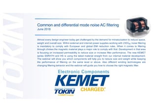
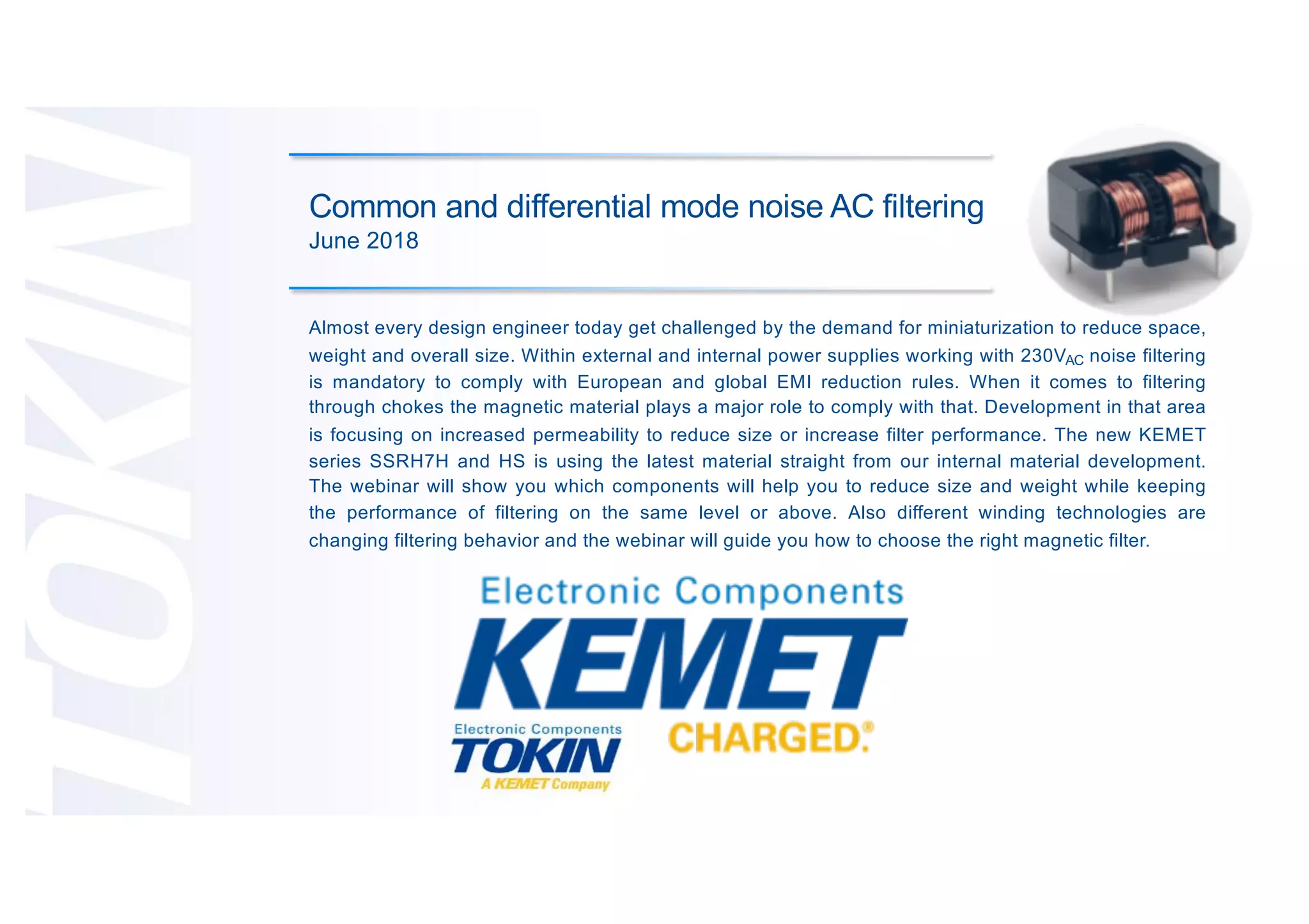
Common and differential mode noise AC filtering
This document discusses noise filtering for AC power supplies. It notes that miniaturization is an important design goal and that noise filtering using chokes is required to meet EMI regulations. The webinar will show how the new KEMET SSRH7H and HS series components can help reduce size and weight while maintaining or improving filtering performance through their magnetic materials and winding technologies. It will also guide attendees on choosing the right magnetic filter and compare components with different permeabilities.
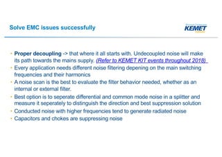
![How to filter conducted noise
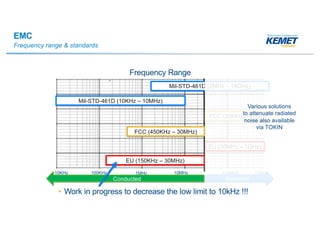
Required frequency range - 150kHz to 30MHz [EU]
• Noise filters use capacitors and inductors
– For 50/60Hz applications the supply frequency should not
be attenuated, but the high frequency noise should
– Capacitors have a high impedance at low frequencies,
however there is always a leakage current to ground
– Inductors have a low impedance at low frequencies with
no leakage current
• With higher frequencies (= noise)...
– Capacitors impedance reduces which guides noise to
ground
– Inductors impedance increases to block noise from
passing the component and therefore passing the line
Z
Z
Inductor/Choke (MAGNETIC)
Noise to block with High Impedance
Capacitor
Noise current lead to ground with
Low Impedance
Typical schematic, simple noise filter](https://image.slidesharecdn.com/commonanddifferentialmodenoiseacfilteringfeb2018-180626134629/85/Common-and-Differential-Mode-Noise-AC-Filtering-11-320.jpg)