Downloaded 18 times
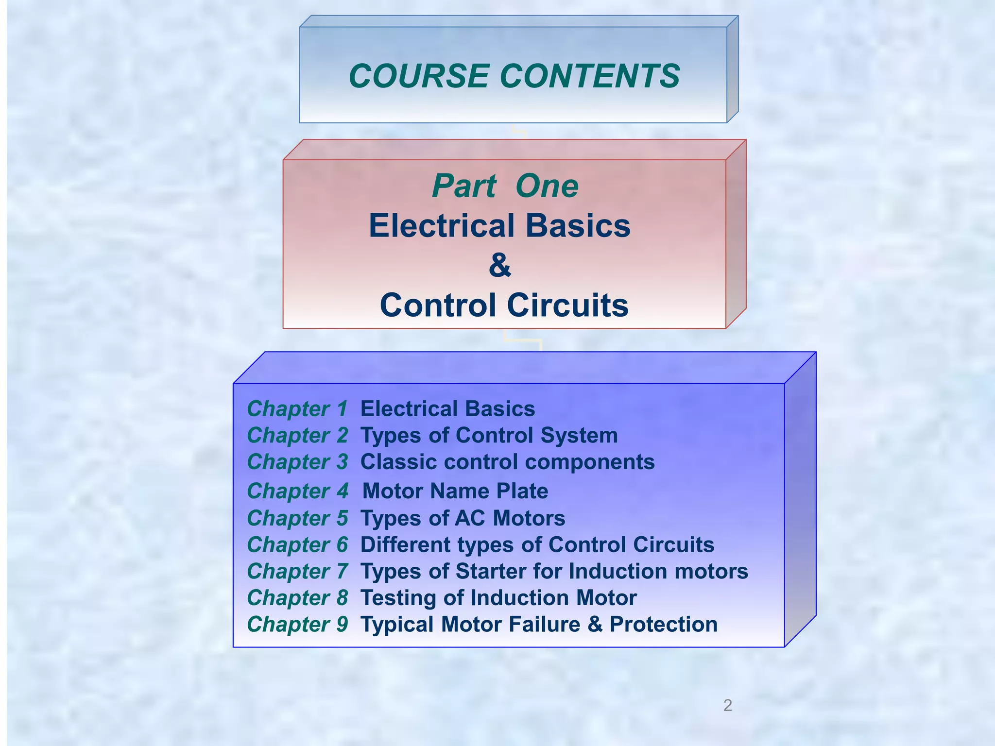
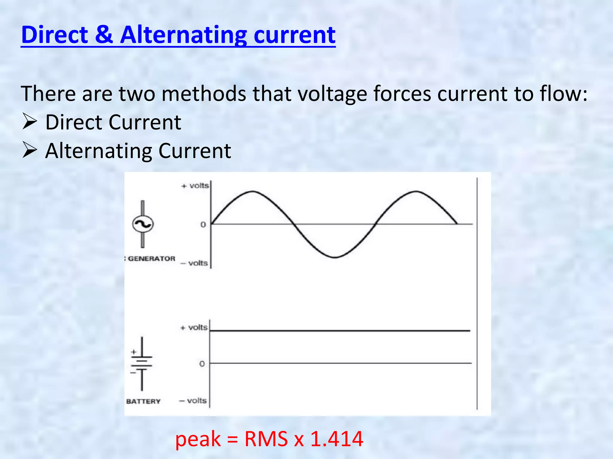
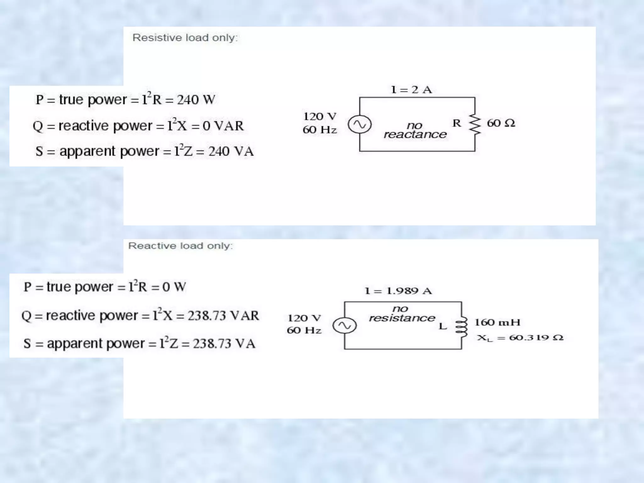
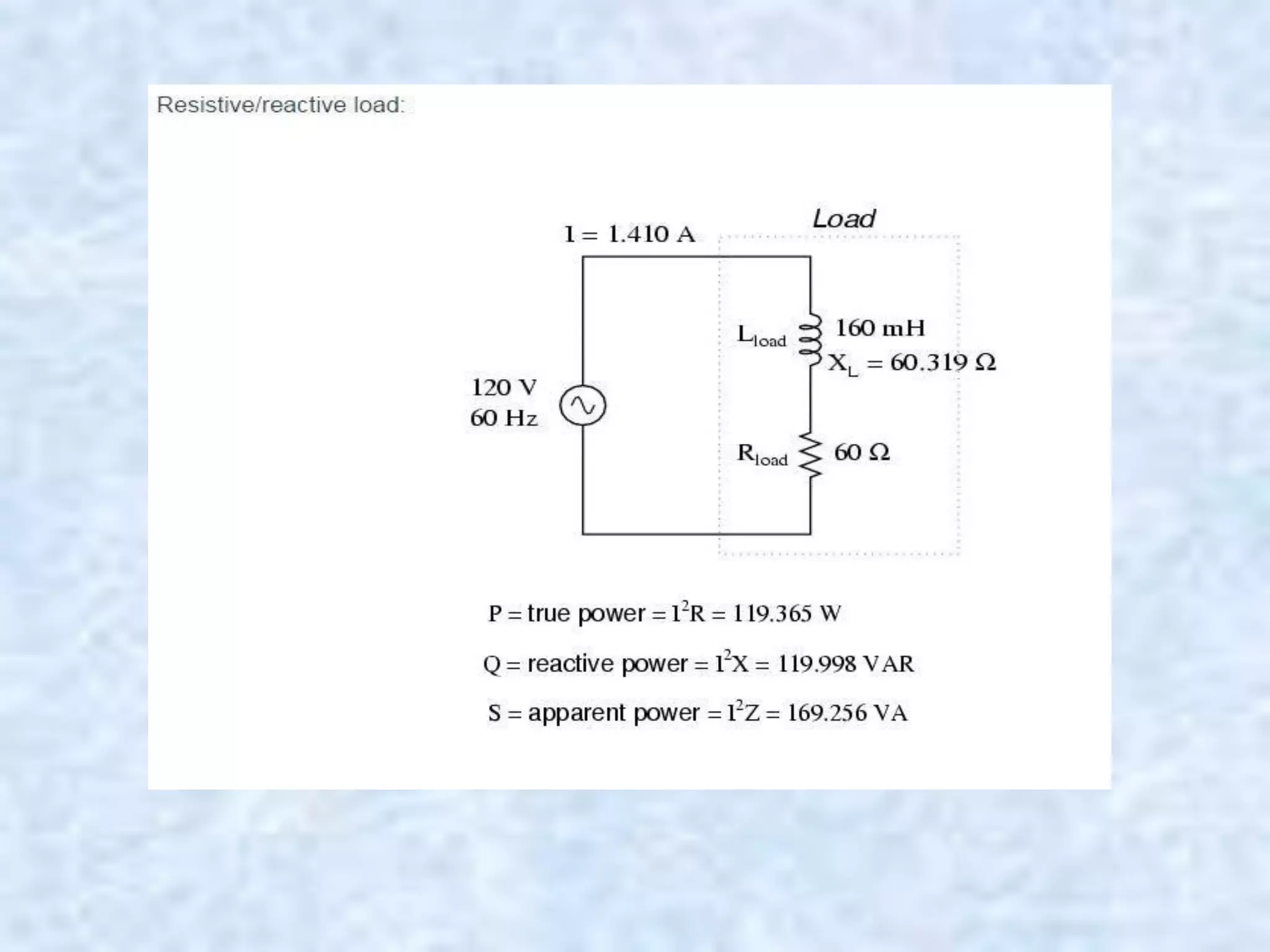

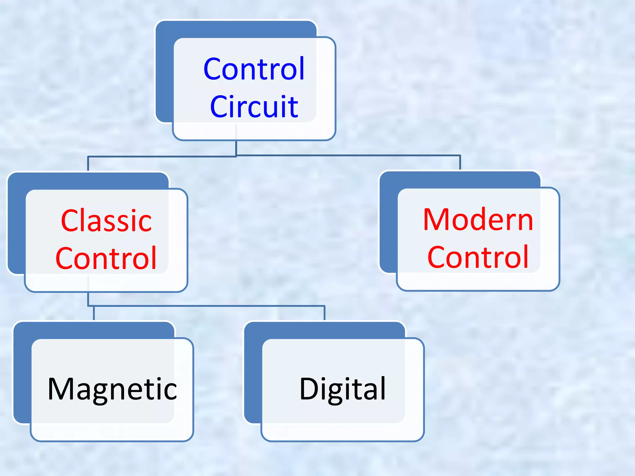
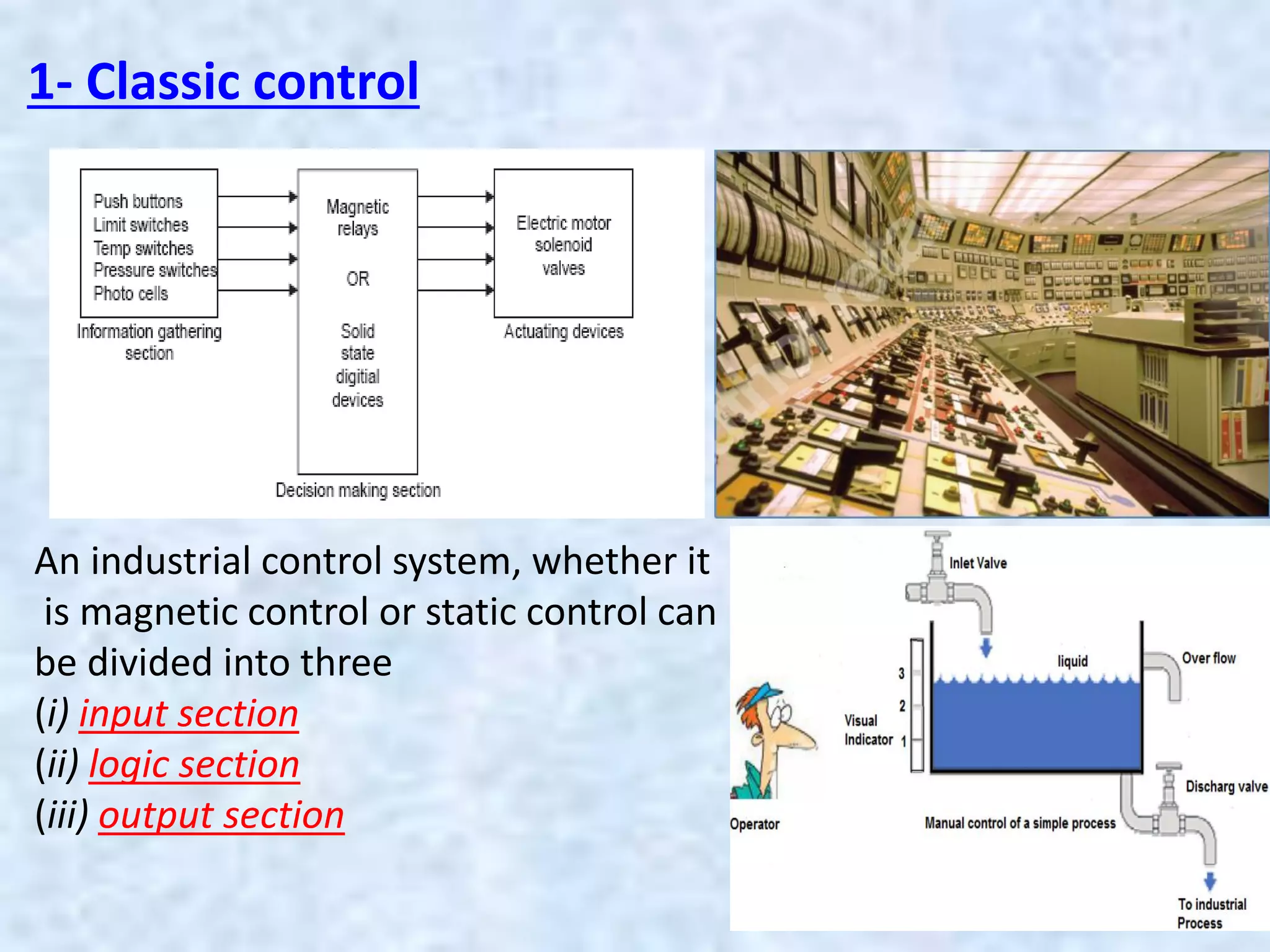
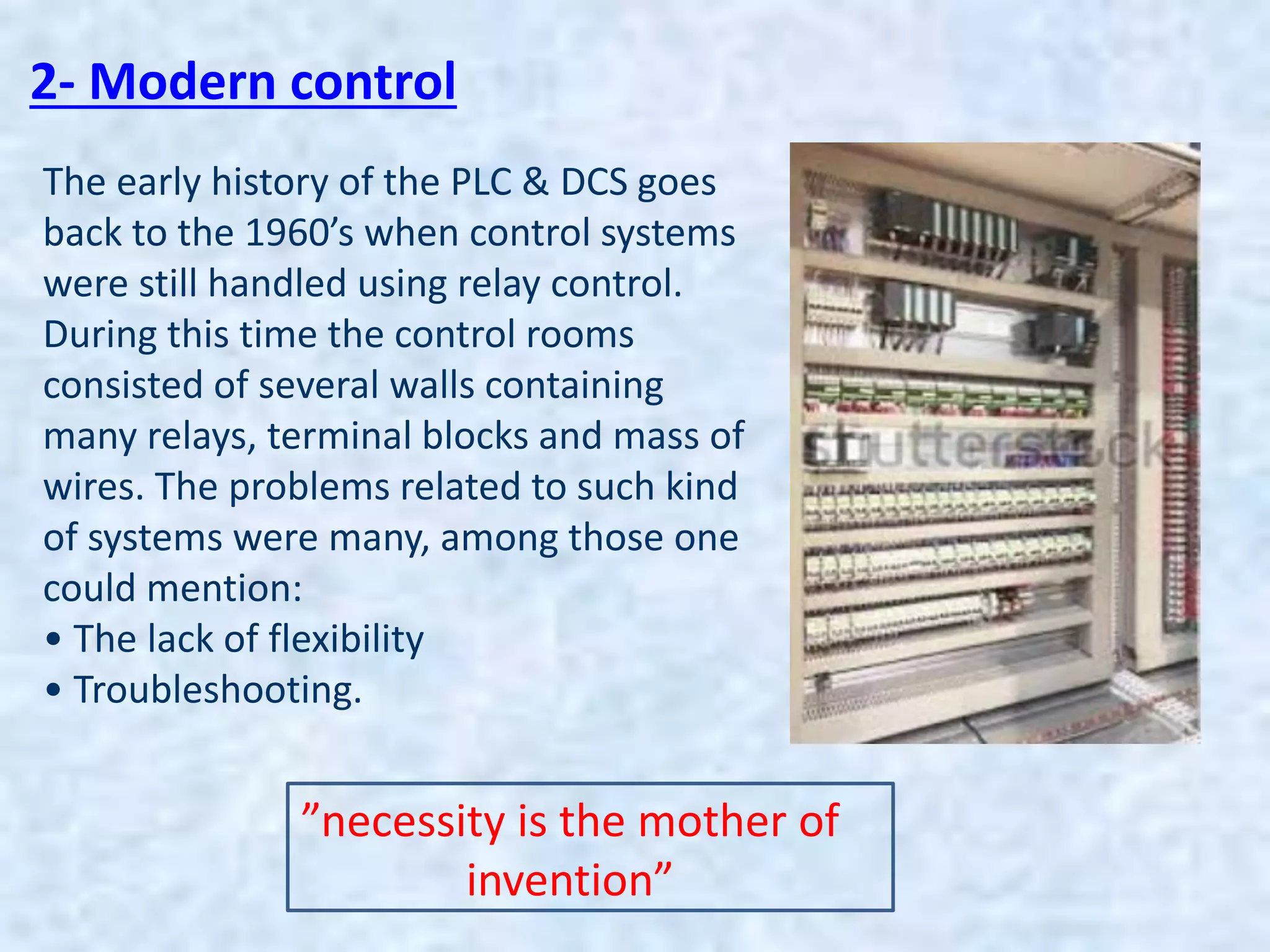
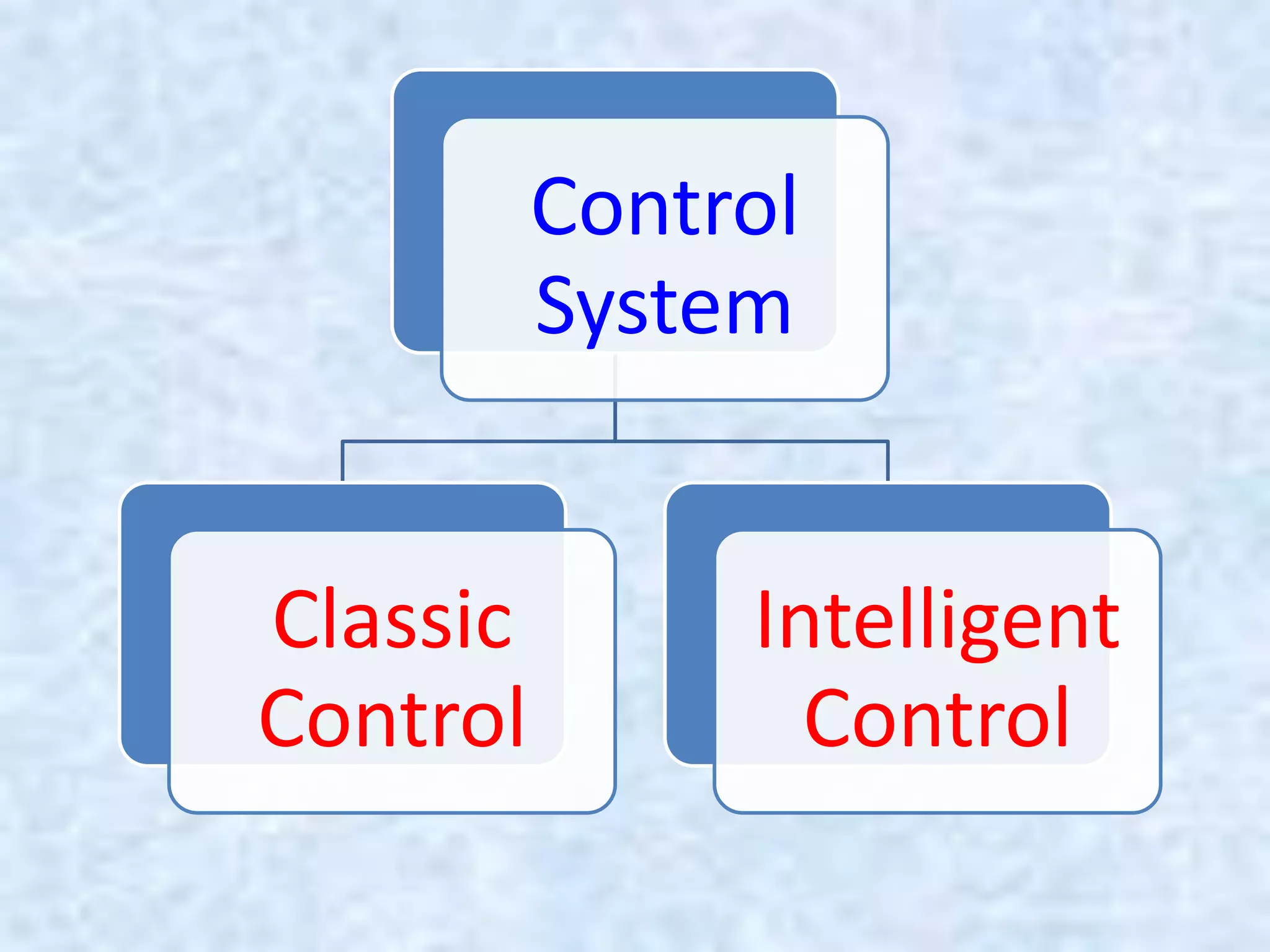


This document provides an overview of electrical basics and classic control systems. It includes 10 chapters that cover topics such as electrical circuits, direct and alternating current, control components, motor nameplates, types of AC motors, and motor control circuits. Chapter 1 discusses basic electrical concepts including circuits, voltage sources, current, and power. Chapter 2 examines different types of control systems including classic and modern control. Chapter 3 focuses on classic control components for power and control circuits.


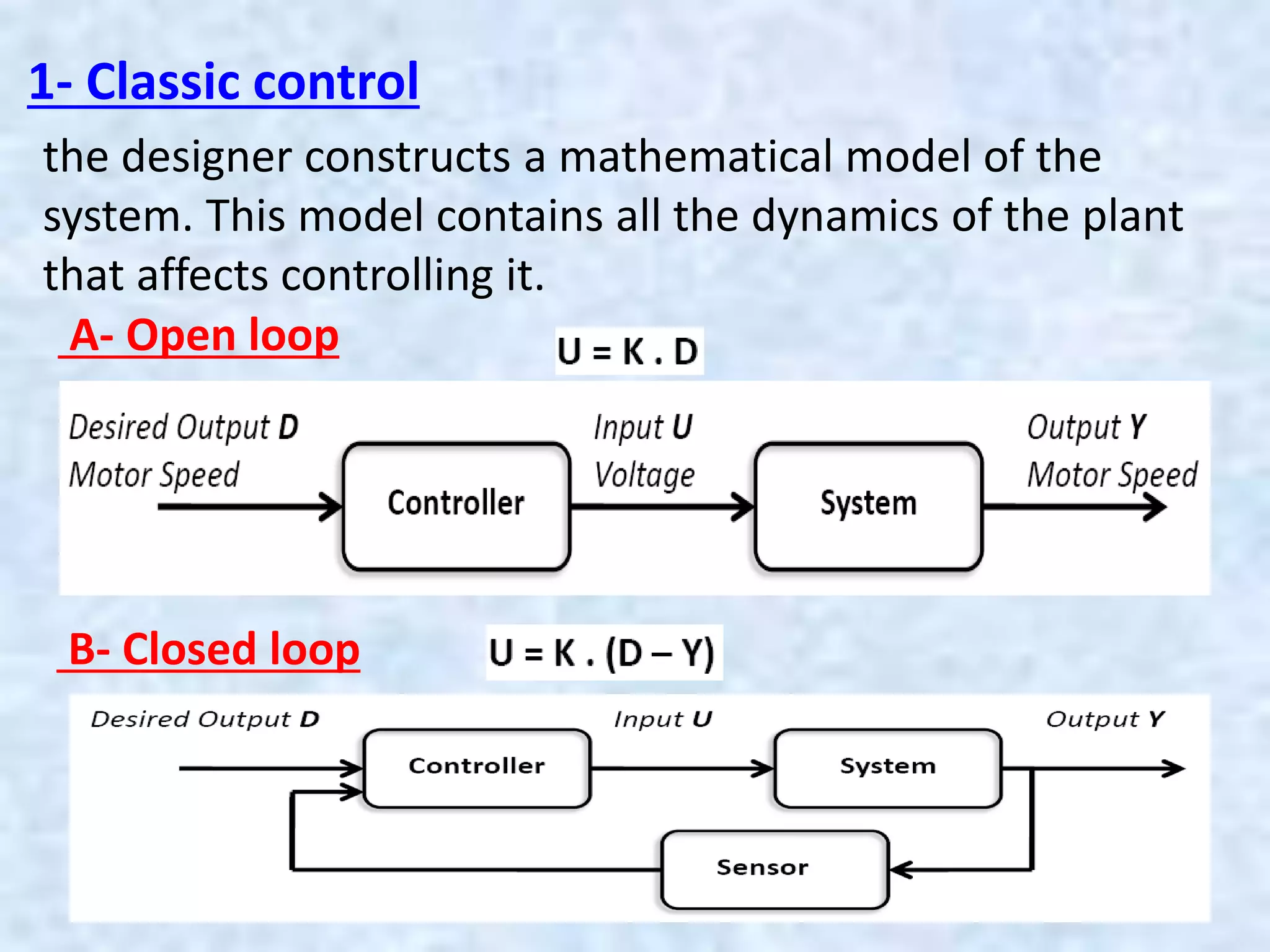
![protection of transmission lines[distance relay protection scheme]](https://cdn.slidesharecdn.com/ss_thumbnails/os-exe3-23-may2011-sr-i-776s21tr-lineprotection-120425095503-phpapp02-thumbnail.jpg?width=640&height=640&fit=bounds)


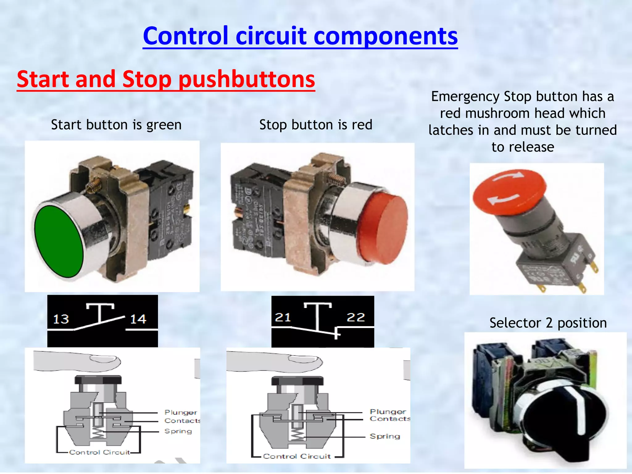
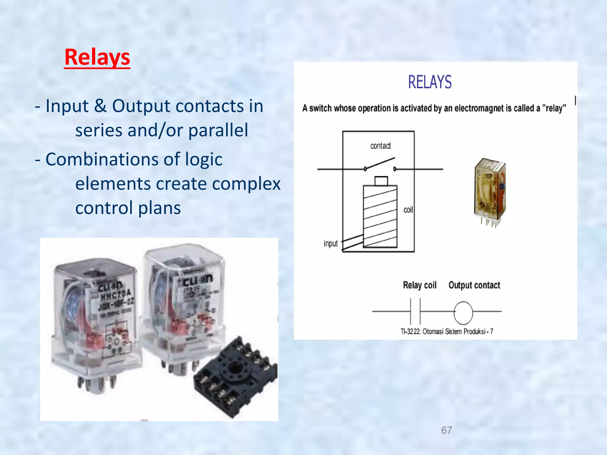
![[Daniel_W._Hart]_Power_Electronic(www.knowing.ir)-1 (1).pdf](https://cdn.slidesharecdn.com/ss_thumbnails/danielw-231119080747-193d829a-thumbnail.jpg?width=640&height=640&fit=bounds)


