Download as PDF, PPTX

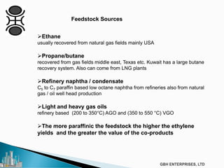
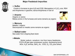
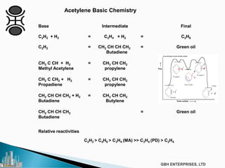
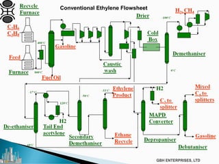
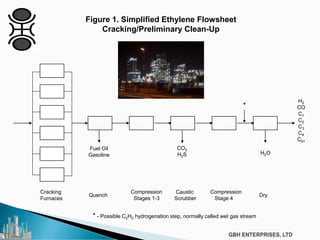
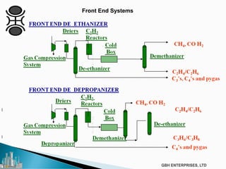
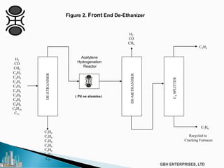
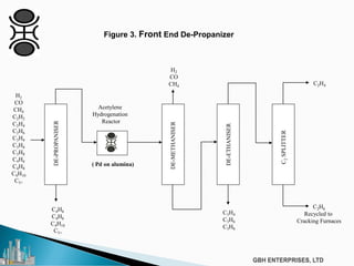
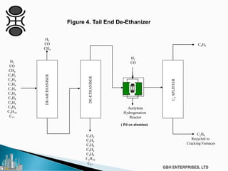
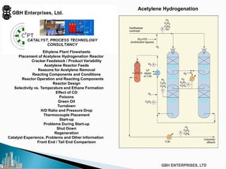


The document discusses the c2pt catalyst process technology for acetylene hydrogenation, detailing various feedstock sources such as ethane, propane/butane, and refinery naphtha. It outlines the significance of feedstock purity and composition on ethylene yields, as well as the chemical processes involved in acetylene hydrogenation and the configurations of ethylene plant flowsheets. Additionally, it highlights operational considerations, reactor design, and the challenges associated with catalyst use and impurities.


![Natural Gas to Olefins, Symposium[2]](https://cdn.slidesharecdn.com/ss_thumbnails/0b411131-d6a1-4822-ad58-dbcc1933154c-150612193624-lva1-app6891-thumbnail.jpg?width=640&height=640&fit=bounds)