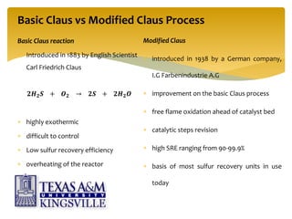
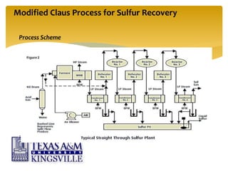
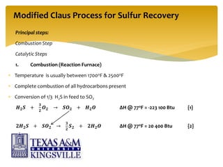
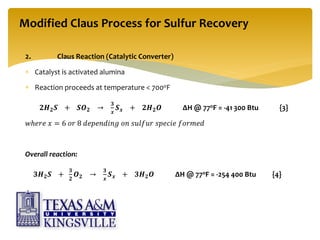
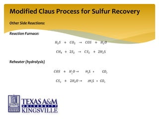
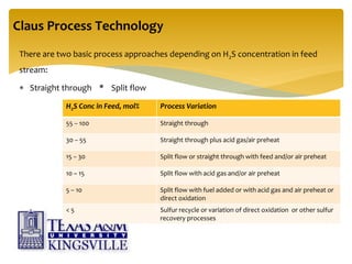
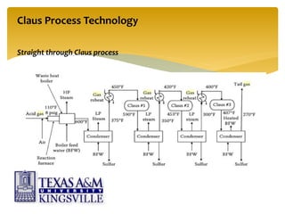
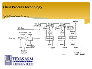
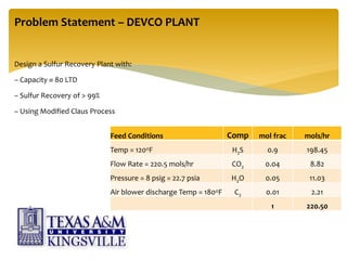
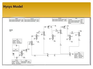
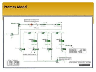
In the plant, ammonia is produced from synthesis gas containing hydrogen and nitrogen in the ratio of approximately 3:1. Besides these components, the synthesis gas contains inert gases such as argon and methane to a limited extent. The source of H2 is demineralized water and the hydrocarbons in the natural gas. The source of N2 is the atmospheric air. The source of CO2 is the hydrocarbons in the natural gas feed. Product ammonia and CO2 is sent to urea plant. The present article intended the description of ammonia plant for natural gas based plants and the possible material balance of some section.
Purpose
Key to good performance
Problem Areas
Catalysts, heat shields and plant up-rates
Burner Guns
Development of High Intensity Ring Burner
Case Studies
Conclusions
1. Introduction reasons for purification, types of poisons, and typical systems
2. Hydrogenation
3. Dechlorination
4. Sulfur Removal
5. Purification system start-up and shut-down
Catalytic Reactions in Catalytic Reforming
Catalytic Reforming Reactions
Sulfur Related Problems
Effects of Sulfur in Catalytic Reforming
Reactions in Catalytic Reforming
Catalytic Reforming Catalysts
Effect of Sulfur on Catalytic Reforming Catalysts
Catalytic Reformer Efficiency
VULCAN Sulfur Guards
VULCAN Sulfur Guards for Catalytic Reformers
VULCAN Guard Installation Protects Isomerization Catalysts
Liquid Phase vs Gas Phase: Relative Advantages
Liquid Phase Treating
Which active metal is best?
Thiophenes and Nickel Sulfur Guards
Sulfiding mechanisms with reduced metals
Thiophene adsorption on nickel
Advantages of Cu/Zn Over Nickel Sulfur Guards
Copper oxide vs Nickel
Nickel Sulfur Guards
Manganese Sulfur Guards
Introduction and Theoretical Aspects
Catalyst Reduction and Start-up
Normal Operation and Troubleshooting
Shutdown and Catalyst Discharge
Nickel Carbonyl Hazard
Modern Methanation Catalyst Requirements
Why have a Secondary Reformer ?
Need nitrogen to make ammonia
Wish to make primary as small as possible
Wish to minimise methane slip since methane is an inert in the ammonia synthesis loop
Other methods of achieving this
Braun Purifier process
Can address all these with an air blown secondary
Most modern ammonia processes are based on steam-reforming of natural gas or naphtha.
The 3 main technology suppliers are Uhde (Uhde/JM Partnership), Topsoe & KBR.
The process steps are very similar in all cases.
Other suppliers are Linde (LAC) & Ammonia Casale.
Calculation of an Ammonia Plant Energy Consumption: Gerard B. Hawkins
Calculation of an Ammonia Plant Energy Consumption:
Case Study: #06023300
Plant Note Book Series: PNBS-0602
CONTENTS
0 SCOPE
1 CALCULATION OF NATURAL GAS PROCESS FEED CONSUMPTION
2 CALCULATION OF NATURAL GAS PROCESS FUEL CONSUMPTION
3 CALCULATION OF NATURAL GAS CONSUMPTION FOR PILOT BURNERS OF FLARES
4 CALCULATION OF DEMIN. WATER FROM DEMIN. UNIT
5 CALCULATION OF DEMIN. WATER TO PACKAGE BOILERS
6 CALCULATION OF MP STEAM EXPORT
7 CALCULATION OF LP STEAM IMPORT
8 DETERMINATION OF ELECTRIC POWER CONSUMPTION
9 DETERMINATION OF THE TOTAL ENERGY CONSUMPTION OF THE AMMONIA PLANT ISBL
10 ADJUSTMENT OF ELECTRIC POWER CONSUMPTION FOR TEST RUN CONDITIONS
11 CALCULATION OF AMMONIA SHARE IN MP STEAM CONSUMPTION IN UTILITIES
12 CALCULATION OF AMMONIA SHARE IN ELECTRIC POWER CONSUMPTION IN UTILITIES
13 DETERMINATION OF THE TOTAL ENERGY CONSUMPTION OF THE AMMONIA PLANT OSBL
14 DETERMINATION OF THE TOTAL ENERGY CONSUMPTION OF THE AMMONIA PLANT
Debottlenecking Claus Sulfur Recovery Units: An Investigation of the applicat...Gerard B. Hawkins
Debottlenecking Claus Sulfur Recovery Units: An Investigation of the application of Zinc Titanates
1 Executive Summary
2 Claus Process
2.1 Partial Combustion Claus
2.2 Split Flow Claus
2.3 Sulfur Recycle Claus
3 Zinc Titanates
4 Application of Zinc Titanate to Debottleneck Partial Combustion Claus by 10%
4.1 Process
4.2 ASPEN Modeling Results
4.3 Cost of Zinc Titanate Bed Installation
4.3.1 Basis of Costing
4.3.2 Zinc Titanate Beds
4.3.3 Regen Cooler
4.3.4 Blowers
4.3.5 Results
4.4 Alternative Debottlenecking Technology for Partial Combustion Claus
4.5 Cost of 10% Debottlenecking Using COPE Process
5 Debottlenecking Claus Split Flow System by 10% with Zinc Titanates
6 Debottlenecking Claus Sulfur Recycle System With Zinc Titanate
7 Effect of Zinc Titanate Debottlenecking on Existing Tail; Gas Treatment Systems
7.1 Selectox
7.2 SuperClaus99
7.3 Superclaus 99.5
7.4 SCOT Process
7.5 Zinc Titanate as a Claus Tail Gas Treatment
7.6 H2S Removal Efficiency With Zinc Titanate
8 Effects on COS and CS2 Formation
9 Questions for further Investigation
FIGURES
Figure 1 Claus Unit and TGCU
Figure 2 Claus Process
Figure 3 Typical Claus Sulfur Recovery Unit
Figure 4 Two-Stage Claus SRU
Figure 5 The Super Claus Process
Figure 6 SCOT
Figure 7 SCOT/BSR-MDEA (or clone) TGCU
REFERENCES: PATENTS
US4333855_PROMOTED_ZINC_TITANATE_CATALYTIC_AGENT
US4394297_ZINC_TITANATE_CATALYST
US6338794B1_DESULFURIZATION_ZINC_TITANATE_SORBENTS
(HTS) High Temperature Shift Catalyst (VSG-F101) - Comprehensiev OverviewGerard B. Hawkins
The high temperature shift duty introduction and theory
HTS catalyst characteristics
developments over time
Typical HTS operational problems
Improved catalysts
VULCAN Series VSG-F101 Series
Summary
This is great Presentation with 3D effects which is all about production of ammonia from natural gas.
I am damn sure you will be getting everything here searching for.
its better to download it and then run in powerpoint 2013.
Revamp objectives
Revamp Philosophy
Revamp options
Semi-Regenerative Reforming Unit
Typical Flow Scheme
Continuous Reforming Unit
Typical Flow Scheme
Revamp to Hybrid Operation
What may be achieved?
Typical C5+ Yield at Decreasing Pressure
Changes Required for Full Conversion
Typical Benefits of Full Conversion
Revamping of Existing Continuous Reforming Units
Fired Heaters Revamp
Burners
Reactor Options
Regeneration Section
Summary
Amine Gas Treating Unit - Best Practices - Troubleshooting Guide Gerard B. Hawkins
Amine Gas Treating Unit Best Practices - Troubleshooting Guide for H2S/CO2 Amine Systems
Contents
Process Capabilities for gas treating process
Typical Amine Treating
Typical Amine System Improvements
Primary Equipment Overview
Inlet Gas Knockout
Absorber
Three Phase Flash Tank
Lean/Rich Heat Exchanger
Regenerator
Filtration
Amine Reclaimer
Operating Difficulties Overview
Foaming
Failure to Meet Gas Specification
Solvent Losses
Corrosion
Typical Amine System Improvements
Degradation of Amines and Alkanolamines during Sour Gas Treating
APPENDIX
Best Practices - Troubleshooting Guide
ALL ABOUT NATURAL GAS : DEFINITION,FORMATION,PROPERTIES,COMPOSITION,PHASE BEHAVIOR ,CONDITIONING"DEHYDRATION ,SWETENING" AND FINAL PROCESSING TO END USER PRODUCTS
We ensure safe execution of all natural gas dehydration processes. Formulated solvents are used for acid gas treatment to achieve proper bio gas processing. If you getting more information about that visit on to http://www.deltapurification.com/ or call (306)-352-6132
Sweetening and sulfur recovery of sour associated gas in the middle eastFrames
Effective and efficient removal of hydrogen sulfide (H2S) is an essential step when sweetening gas for downstream processes. By simultaneously turning the captured hydrogen sulfide into elemental sulfur, a Frames THIOPAQ O&G system improves gas value, while creating a saleable chemical widely sought after in the agricultural and bulk chemical industry.
Sweetening and sulfur recovery of sour associated gas and lean acid gas in th...Frames
Effective and efficient removal of hydrogen sulfide (H2S) is an essential step when sweetening gas for downstream processes. By simultaneously turning the captured hydrogen sulfide into elemental sulfur, a Frames THIOPAQ O&G system improves gas value, while creating a saleable chemical widely sought after in the agricultural and bulk chemical industry.
Natural gas processing: Production of LPG Asma-ul Husna
This is a presentation on a process designed for a natural gas processing plant that can use NGL and condensate to produce LPG. The designed process yields a product with 50 percent of propane and 20 percent of butane, which meets the specification for a high quality LPG.
Gasifi cation is a process in which combustible materials are partially oxi-dized or partially combusted. The product of gasifi cation is a combustible synthesis gas, or syngas. Because gasifi cation involves the partial, rather than complete, oxidization of the feed, gasifi cation processes operate in an oxygen-lean environment. As fi gure 1 indicates, the stoichiometric oxygen-to-coal ratio for combustion is almost four times the stoichiometric oxygen-to-coal ratio for gasifi cation of Illinois #6coal.
5. Basic Claus vs Modified Claus Process
Basic Claus reaction
Introduced in 1883 by English Scientist
Carl Friedrich Claus
𝟐𝑯 𝟐 𝑺 + 𝑶 𝟐 → 𝟐𝑺 + 𝟐𝑯 𝟐 𝑶
highly exothermic
difficult to control
Low sulfur recovery efficiency
overheating of the reactor
Modified Claus
introduced in 1938 by a German company,
I.G Farbenindustrie A.G
improvement on the basic Claus process
free flame oxidation ahead of catalyst bed
catalytic steps revision
high SRE ranging from 90-99.9%
basis of most sulfur recovery units in use
today
9. Other Side Reactions:
Reaction Furnace:
𝐻2 𝑆 + 𝐶𝑂2 → 𝐶𝑂𝑆 + 𝐻2 𝑂
𝐶𝐻4 + 2𝑆2 → 𝐶𝑆2 + 2𝐻2S
Reheater (hydrolysis)
𝐶𝑂𝑆 + 𝐻2
𝑂 → H2S + CO2
𝐶𝑆2 + 2𝐻2 𝑂 → 2H2S + CO2
Modified Claus Process for Sulfur Recovery
10. Process Control:
Optimum conversion of H2S to sulfur is governed by:
constant 2:1 stoichiometric ratio of H2S to SO2
achieved by varying furnace air flow rate
deviation from ratio results in decreased SRE
Modified Claus Process for Sulfur Recovery
11. There are two basic process approaches depending on H2S concentration in feed
stream:
Straight through * Split flow
Claus Process Technology
H2S Conc in Feed, mol% Process Variation
55 – 100 Straight through
30 – 55 Straight through plus acid gas/air preheat
15 – 30 Split flow or straight through with feed and/or air preheat
10 – 15 Split flow with acid gas and/or air preheat
5 – 10 Split flow with fuel added or with acid gas and air preheat or
direct oxidation
< 5 Sulfur recycle or variation of direct oxidation or other sulfur
recovery processes
14. Other Variations
Oxygen Enrichment
use of pure oxygen instead of air
higher and stable flame temperatures
low H2S concentration feed and smaller equipment use
used in combination with other variations
Acid Gas Enrichment
applied ahead of SRU to achieve richer acid gas stream
a solvent that selectively absorbs all the H2S from the feed gas stream is used
The straight through process can then be used for sulfur recovery
Claus Process Technology
15. Tail Gas:
Contains N2, CO2, H2O, CO, H2, unreacted H2S and SO2, COS, CS2, sulfur vapor, etc.
Limits overall sulfur recovery efficiency to 96-97%
Tail gas is incinerated or treated in TGCU depending on local EPA regulation
Incineration - < 5000 ppmv H2S
< 2500 ppmv SO2
TGCU Processes (Tail Gas Clean Up)
higher H2S conversion efficiencies (>99.9 %)
further reduction in SO2 amount vented out
Claus Tail Gas Handling
16. TGCU (Tail Gas Clean Up) Processes
Process Example Company
1. Sub-dewpoint Processes Cold Bed Adsorption (CBA) BP Amoco, Black & Veatch
2. Direct Oxidation SuperClaus, MODOP Jacobs Engineering & Mobil
3. SO2 Recovery Well-man Lord Luigi Bamag
(oxidize to SO2, absorb and
recycle to Claus)
4. H2S Recovery BSR Parsons
(reduce to H2S, absorb &
recycle to Claus)
SCOT
MDEA
Shell
UOP
20. Sulfur & its properties
Solid at ambient temperatures
Solid sulfur at ambient temperature
Gaseous sulfur allotropes
S8
S6
S2
S3, S4, S5, S7 – detected but not fully characterized
Sulfur
Crystalline Amorphous
slowly changes to
rhombic form at
ambient temperaturesRhombic Monoclinic
stable at <
204°F
stable at
>204oF
prepared by rapidly
chilling liquid sulfur
Both exists in octatomic
crystalline structures
presence not desired
28. Result – Hand Calculation
Furnace Temperature & Conversion:
From Equilibrium constant chart
x (mols/hr) (assumed)
Kp (calculated) Equilibrium
Temp (F)
89.52 20.00351623 1875
93.54
30.01536222
2150
96.231 40.00228095 2387.5
x (mols/hr)
Equilibrium
Temp (Fig
Flame
Temperatute (F)
89.52 1875 2,479.68
93.54 2150 2,474.45
96.231 2400 2,395.94
From Plot:
x = 96.2 mols/hr
This is amt of H2S that actually reacted
(96.2/132.3)*100%
% Conversion in furnace = 72.71 %
Furnace Temp = 2390 F
29. Result – Hand Calculation
y, mols/hr
Stream
Enthalpy
(Btu/hr)
Converter Heat
Balance (Btu/hr)
20.15 2,908,018 2,638,763
21.96 2,795,414 2,766,609
23.13 2,573,013 2,792,969
From Plot,
y = 22.18mols/hr
% Conversion = (22.18*(2/3 H2S in feed) = 16.76 %
At y = 22.18 mols/hr, Kp = 3166.17
@ Kp = 3166.17 T = 603 F
Converter Outlet Temperature = 603 F
1st Catalyst Converter
30. Result - Hand Calculation
2nd catalytic converter outlet temperature 3rd catalytic converter outlet temperature