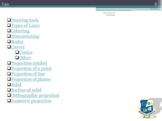
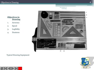
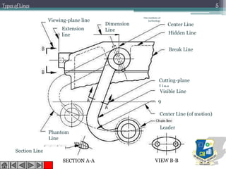
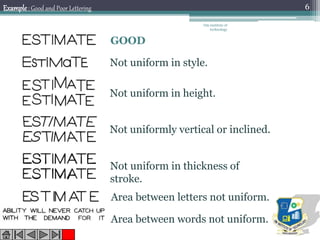
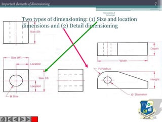
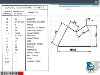
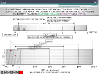
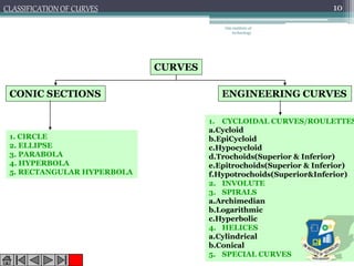
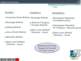
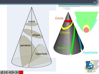
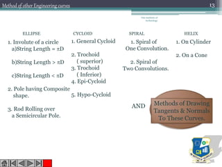
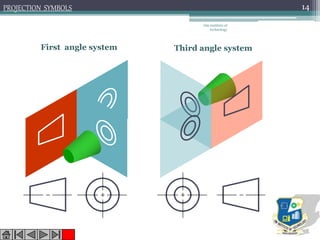
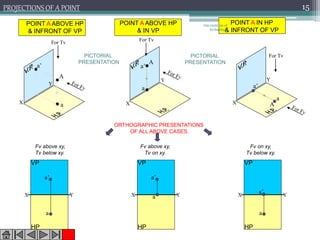
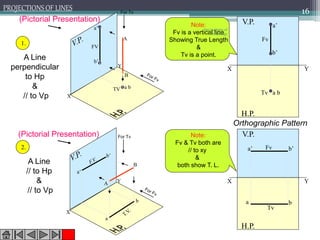
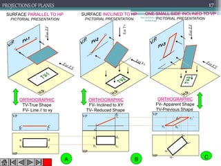
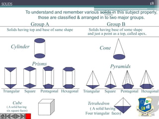
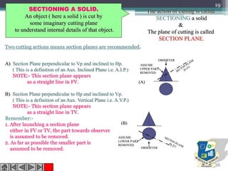
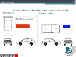
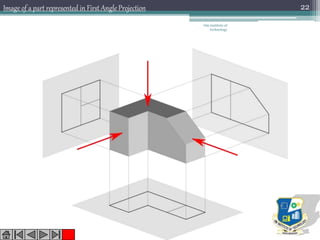
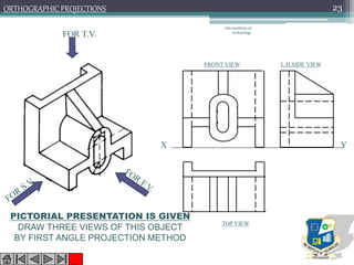
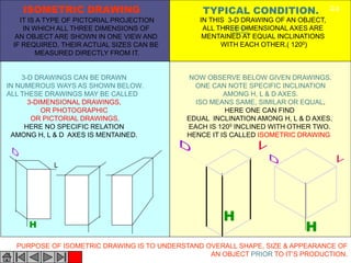
Subject code: 2110013
Om institute of
technology
2
Om institute of
technology
3Topic
Drawing tools
Types of Lines
Lettering
Dimensioning
Scales
Curves
Conics
Other
Projection symbol
Projection of a point
Projection of line
Projection of planes
Solid
Section of solid
Orthographic projection
Isometric projection
Om institute of
technology
4Objectives in Drawing
Typical Drawing Equipment
Objectives in
Drawing
1. Accuracy
2. Speed
3. Legibility
4. Neatness
1
2
3 4
5
6
7
8
9
10
14
13
12 11
Viewing-plane line
Extension
line
Dimension
Line
Center Line
Hidden Line
Break Line
Cutting-plane
Line
Visible Line
Center Line (of motion)
Leader
VIEW B-BSECTION A-A
Section Line
Phantom
Line
Om institute of
technology
5Types of Lines
GOOD
Not uniform in style.
Not uniform in height.
Not uniformly vertical or inclined.
Not uniform in thickness of
stroke.
Area between letters not uniform.
Area between words not uniform.
Example: Good and Poor Lettering
Om institute of
technology
6
Om institute of
technology
7Important elements of dimensioning
Two types of dimensioning: (1) Size and location
dimensions and (2) Detail dimensioning
Om institute of
technology
8
Om institute of
technology
9
DIMENSIONS OF LARGE OBJECTS MUST BE REDUCED TO ACCOMMODATE ON STANDARD SIZE
DRAWING SHEET. THIS REDUCTION CREATES A SCALE OF THAT REDUCTION RATIO, WHICH IS
GENERALLY A FRACTION..THAT RATIO IS CALLED REPRESENTATIVE FACTOR.
REPRESENTATIVE FACTOR (R.F.) =
DIMENSION OF DRAWING
DIMENSION OF OBJECT
0 1 2 3 4 510 METERS
DECIMETERS R.F. = 1/100
4 M 6 DM
PLANE SCALE SHOWING METERS AND DECIMETERS.
R.F. = 1 / 40,00,000
DIAGONAL SCALE SHOWING KILOMETERS.
0 100 200 300 400 500100 50
1
0
9
8
7
6
5
4
3
2
1
0
KM
KM
KM
569 km
459 km
336 km
222 km
Scales
Om institute of
technology
10CLASSIFICATION OF CURVES
CURVES
CONIC SECTIONS ENGINEERING CURVES
1. CIRCLE
2. ELLIPSE
3. PARABOLA
4. HYPERBOLA
5. RECTANGULAR HYPERBOLA
1. CYCLOIDAL CURVES/ROULETTES
a.Cycloid
b.EpiCycloid
c.Hypocycloid
d.Trochoids(Superior & Inferior)
e.Epitrochoids(Superior & Inferior)
f.Hypotrochoids(Superior&Inferior)
2. INVOLUTE
3. SPIRALS
a.Archimedian
b.Logarithmic
c.Hyperbolic
4. HELICES
a.Cylindrical
b.Conical
5. SPECIAL CURVES
Om institute of
technology
11
ELLIPSE
1.Concentric Circle Method
2.Rectangle Method
3.Oblong Method
4.Arcs of Circle Method
5.Rhombus Method
6.Basic Locus Method
(Directrix – focus)
HYPERBOLA
1.Rectangular Hyperbola
(coordinates given)
2 Rectangular Hyperbola
(P-V diagram - Equation given)
3.Basic Locus Method
(Directrix – focus)
PARABOLA
1.Rectangle Method
2 Method of Tangents
( Triangle Method)
3.Basic Locus Method
(Directrix – focus)
Methods of Drawing
Tangents & Normals
To These Curves.
Methods in Conic sections
Om institute of
technology
12
Om institute of
technology
13
ELLIPSE CYCLOID SPIRAL HELIX
1. Involute of a circle
a)String Length = D
b)String Length > D
c)String Length < D
2. Pole having Composite
shape.
3. Rod Rolling over
a Semicircular Pole.
1. General Cycloid
2. Trochoid
( superior)
3. Trochoid
( Inferior)
4. Epi-Cycloid
5. Hypo-Cycloid
1. Spiral of
One Convolution.
2. Spiral of
Two Convolutions.
1. On Cylinder
2. On a Cone
Methods of Drawing
Tangents & Normals
To These Curves.
AND
Method of other Engineering curves
First angle system Third angle system
PROJECTION SYMBOLS
Om institute of
technology
14
A
a
a’
A
a
a’
A
a
a’
X
Y
X
Y
X
Y
For Tv
For Tv
For Tv
POINT A ABOVE HP
& INFRONT OF VP
POINT A IN HP
& INFRONT OF VP
POINT A ABOVE HP
& IN VP
PROJECTIONS OF A POINT
PICTORIAL
PRESENTATION
PICTORIAL
PRESENTATION
ORTHOGRAPHIC PRESENTATIONS
OF ALL ABOVE CASES.
X Y
a
a’
VP
HP
X Y
a’
VP
HP
a X Y
a
VP
HP
a’
Fv above xy,
Tv below xy.
Fv above xy,
Tv on xy.
Fv on xy,
Tv below xy.
Om institute of
technology
15
X
Y
X
Y
b’
a’
b
a
a b
a’
b’
B
A
TV
FV
A
B
X Y
H.P.
V.P. a’
b’
a b
Fv
Tv
X Y
H.P.
V.P.
a b
a’ b’Fv
Tv
For Tv
For Tv
Note:
Fv is a vertical line
Showing True Length
&
Tv is a point.
Note:
Fv & Tv both are
// to xy
&
both show T. L.
1.
2.
A Line
perpendicular
to Hp
&
// to Vp
A Line
// to Hp
&
// to Vp
Orthographic Pattern
(Pictorial Presentation)
Om institute of
technology
16PROJECTIONS OF LINES
HP
VP
VPVP
a’ d’
c’b’
HP
a
b c
d
a1’
d1’ c1’
b1’
HP
a1
b1 c1
d1
SURFACE PARALLEL TO HP
PICTORIAL PRESENTATION
SURFACE INCLINED TO HP
PICTORIAL PRESENTATION
ONE SMALL SIDE INCLINED TO VP
PICTORIAL PRESENTATION
ORTHOGRAPHIC
TV-True Shape
FV- Line // to xy
ORTHOGRAPHIC
FV- Inclined to XY
TV- Reduced Shape
ORTHOGRAPHIC
FV- Apparent Shape
TV-Previous Shape
A B C
Om institute of
technology
17PROJECTIONS OF PLANES
SOLIDS
To understand and remember various solids in this subject properly,
those are classified & arranged in to two major groups.
Group A
Solids having top and base of same shape
Cylinder
Prisms
Triangular Square Pentagonal Hexagonal
Cube
Triangular Square Pentagonal Hexagonal
Cone
Tetrahedron
Pyramids
( A solid having
six square faces)
( A solid having
Four triangular faces)
Group B
Solids having base of some shape
and just a point as a top, called apex.
Om institute of
technology
18
SECTIONING A SOLID.
An object ( here a solid ) is cut by
some imaginary cutting plane
to understand internal details of that object.
The action of cutting is called
SECTIONING a solid
&
The plane of cutting is called
SECTION PLANE.
Two cutting actions means section planes are recommended.
A) Section Plane perpendicular to Vp and inclined to Hp.
( This is a definition of an Aux. Inclined Plane i.e. A.I.P.)
NOTE:- This section plane appears
as a straight line in FV.
B) Section Plane perpendicular to Hp and inclined to Vp.
( This is a definition of an Aux. Vertical Plane i.e. A.V.P.)
NOTE:- This section plane appears
as a straight line in TV.
Remember:-
1. After launching a section plane
either in FV or TV, the part towards observer
is assumed to be removed.
2. As far as possible the smaller part is
assumed to be removed.
OBSERVER
ASSUME
UPPER PART
REMOVED
OBSERVER
ASSUME
LOWER PART
REMOVED
(A)
(B)
19
TOP VIEW
R22
2040
10
FRONT VIEW
RIGHT SIDE
VIEW
14020
80
SCALE: 1:1
3030
66
26
30
Om institute of
technology
20
Select a Front View
The object’s longest dimension should be presented as a width.
Inappropriate
First choice
GOOD
Second choice
Waste more space
Om institute of
technology
21
Om institute of
technology
22Image of a part represented in First Angle Projection
FOR T.V.
PICTORIAL PRESENTATION IS GIVEN
DRAW THREE VIEWS OF THIS OBJECT
BY FIRST ANGLE PROJECTION METHOD
ORTHOGRAPHIC PROJECTIONS
FRONT VIEW
TOP VIEW
L.H.SIDE VIEW
X Y
Om institute of
technology
23
H
3-D DRAWINGS CAN BE DRAWN
IN NUMEROUS WAYS AS SHOWN BELOW.
ALL THESE DRAWINGS MAY BE CALLED
3-DIMENSIONAL DRAWINGS,
OR PHOTOGRAPHIC
OR PICTORIAL DRAWINGS.
HERE NO SPECIFIC RELATION
AMONG H, L & D AXES IS MENTAINED.
H
NOW OBSERVE BELOW GIVEN DRAWINGS.
ONE CAN NOTE SPECIFIC INCLINATION
AMONG H, L & D AXES.
ISO MEANS SAME, SIMILAR OR EQUAL.
HERE ONE CAN FIND
EDUAL INCLINATION AMONG H, L & D AXES.
EACH IS 1200 INCLINED WITH OTHER TWO.
HENCE IT IS CALLED ISOMETRIC DRAWING
H
L
IT IS A TYPE OF PICTORIAL PROJECTION
IN WHICH ALL THREE DIMENSIONS OF
AN OBJECT ARE SHOWN IN ONE VIEW AND
IF REQUIRED, THEIR ACTUAL SIZES CAN BE
MEASURED DIRECTLY FROM IT.
IN THIS 3-D DRAWING OF AN OBJECT,
ALL THREE DIMENSIONAL AXES ARE
MENTAINED AT EQUAL INCLINATIONS
WITH EACH OTHER.( 1200)
PURPOSE OF ISOMETRIC DRAWING IS TO UNDERSTAND OVERALL SHAPE, SIZE & APPEARANCE OF
AN OBJECT PRIOR TO IT’S PRODUCTION.
ISOMETRIC DRAWING TYPICAL CONDITION.
Om institute of
technology
24
Om institute of
technology
25

Engineering graphics 2110013

  • 1.
  • 2.
  • 3.
    Om institute of technology 3Topic Drawingtools Types of Lines Lettering Dimensioning Scales Curves Conics Other Projection symbol Projection of a point Projection of line Projection of planes Solid Section of solid Orthographic projection Isometric projection
  • 4.
    Om institute of technology 4Objectivesin Drawing Typical Drawing Equipment Objectives in Drawing 1. Accuracy 2. Speed 3. Legibility 4. Neatness
  • 5.
    1 2 3 4 5 6 7 8 9 10 14 13 12 11 Viewing-planeline Extension line Dimension Line Center Line Hidden Line Break Line Cutting-plane Line Visible Line Center Line (of motion) Leader VIEW B-BSECTION A-A Section Line Phantom Line Om institute of technology 5Types of Lines
  • 6.
    GOOD Not uniform instyle. Not uniform in height. Not uniformly vertical or inclined. Not uniform in thickness of stroke. Area between letters not uniform. Area between words not uniform. Example: Good and Poor Lettering Om institute of technology 6
  • 7.
    Om institute of technology 7Importantelements of dimensioning Two types of dimensioning: (1) Size and location dimensions and (2) Detail dimensioning
  • 8.
  • 9.
    Om institute of technology 9 DIMENSIONSOF LARGE OBJECTS MUST BE REDUCED TO ACCOMMODATE ON STANDARD SIZE DRAWING SHEET. THIS REDUCTION CREATES A SCALE OF THAT REDUCTION RATIO, WHICH IS GENERALLY A FRACTION..THAT RATIO IS CALLED REPRESENTATIVE FACTOR. REPRESENTATIVE FACTOR (R.F.) = DIMENSION OF DRAWING DIMENSION OF OBJECT 0 1 2 3 4 510 METERS DECIMETERS R.F. = 1/100 4 M 6 DM PLANE SCALE SHOWING METERS AND DECIMETERS. R.F. = 1 / 40,00,000 DIAGONAL SCALE SHOWING KILOMETERS. 0 100 200 300 400 500100 50 1 0 9 8 7 6 5 4 3 2 1 0 KM KM KM 569 km 459 km 336 km 222 km Scales
  • 10.
    Om institute of technology 10CLASSIFICATIONOF CURVES CURVES CONIC SECTIONS ENGINEERING CURVES 1. CIRCLE 2. ELLIPSE 3. PARABOLA 4. HYPERBOLA 5. RECTANGULAR HYPERBOLA 1. CYCLOIDAL CURVES/ROULETTES a.Cycloid b.EpiCycloid c.Hypocycloid d.Trochoids(Superior & Inferior) e.Epitrochoids(Superior & Inferior) f.Hypotrochoids(Superior&Inferior) 2. INVOLUTE 3. SPIRALS a.Archimedian b.Logarithmic c.Hyperbolic 4. HELICES a.Cylindrical b.Conical 5. SPECIAL CURVES
  • 11.
    Om institute of technology 11 ELLIPSE 1.ConcentricCircle Method 2.Rectangle Method 3.Oblong Method 4.Arcs of Circle Method 5.Rhombus Method 6.Basic Locus Method (Directrix – focus) HYPERBOLA 1.Rectangular Hyperbola (coordinates given) 2 Rectangular Hyperbola (P-V diagram - Equation given) 3.Basic Locus Method (Directrix – focus) PARABOLA 1.Rectangle Method 2 Method of Tangents ( Triangle Method) 3.Basic Locus Method (Directrix – focus) Methods of Drawing Tangents & Normals To These Curves. Methods in Conic sections
  • 12.
  • 13.
    Om institute of technology 13 ELLIPSECYCLOID SPIRAL HELIX 1. Involute of a circle a)String Length = D b)String Length > D c)String Length < D 2. Pole having Composite shape. 3. Rod Rolling over a Semicircular Pole. 1. General Cycloid 2. Trochoid ( superior) 3. Trochoid ( Inferior) 4. Epi-Cycloid 5. Hypo-Cycloid 1. Spiral of One Convolution. 2. Spiral of Two Convolutions. 1. On Cylinder 2. On a Cone Methods of Drawing Tangents & Normals To These Curves. AND Method of other Engineering curves
  • 14.
    First angle systemThird angle system PROJECTION SYMBOLS Om institute of technology 14
  • 15.
    A a a’ A a a’ A a a’ X Y X Y X Y For Tv For Tv ForTv POINT A ABOVE HP & INFRONT OF VP POINT A IN HP & INFRONT OF VP POINT A ABOVE HP & IN VP PROJECTIONS OF A POINT PICTORIAL PRESENTATION PICTORIAL PRESENTATION ORTHOGRAPHIC PRESENTATIONS OF ALL ABOVE CASES. X Y a a’ VP HP X Y a’ VP HP a X Y a VP HP a’ Fv above xy, Tv below xy. Fv above xy, Tv on xy. Fv on xy, Tv below xy. Om institute of technology 15
  • 16.
    X Y X Y b’ a’ b a a b a’ b’ B A TV FV A B X Y H.P. V.P.a’ b’ a b Fv Tv X Y H.P. V.P. a b a’ b’Fv Tv For Tv For Tv Note: Fv is a vertical line Showing True Length & Tv is a point. Note: Fv & Tv both are // to xy & both show T. L. 1. 2. A Line perpendicular to Hp & // to Vp A Line // to Hp & // to Vp Orthographic Pattern (Pictorial Presentation) (Pictorial Presentation) Om institute of technology 16PROJECTIONS OF LINES
  • 17.
    HP VP VPVP a’ d’ c’b’ HP a b c d a1’ d1’c1’ b1’ HP a1 b1 c1 d1 SURFACE PARALLEL TO HP PICTORIAL PRESENTATION SURFACE INCLINED TO HP PICTORIAL PRESENTATION ONE SMALL SIDE INCLINED TO VP PICTORIAL PRESENTATION ORTHOGRAPHIC TV-True Shape FV- Line // to xy ORTHOGRAPHIC FV- Inclined to XY TV- Reduced Shape ORTHOGRAPHIC FV- Apparent Shape TV-Previous Shape A B C Om institute of technology 17PROJECTIONS OF PLANES
  • 18.
    SOLIDS To understand andremember various solids in this subject properly, those are classified & arranged in to two major groups. Group A Solids having top and base of same shape Cylinder Prisms Triangular Square Pentagonal Hexagonal Cube Triangular Square Pentagonal Hexagonal Cone Tetrahedron Pyramids ( A solid having six square faces) ( A solid having Four triangular faces) Group B Solids having base of some shape and just a point as a top, called apex. Om institute of technology 18
  • 19.
    SECTIONING A SOLID. Anobject ( here a solid ) is cut by some imaginary cutting plane to understand internal details of that object. The action of cutting is called SECTIONING a solid & The plane of cutting is called SECTION PLANE. Two cutting actions means section planes are recommended. A) Section Plane perpendicular to Vp and inclined to Hp. ( This is a definition of an Aux. Inclined Plane i.e. A.I.P.) NOTE:- This section plane appears as a straight line in FV. B) Section Plane perpendicular to Hp and inclined to Vp. ( This is a definition of an Aux. Vertical Plane i.e. A.V.P.) NOTE:- This section plane appears as a straight line in TV. Remember:- 1. After launching a section plane either in FV or TV, the part towards observer is assumed to be removed. 2. As far as possible the smaller part is assumed to be removed. OBSERVER ASSUME UPPER PART REMOVED OBSERVER ASSUME LOWER PART REMOVED (A) (B) 19
  • 20.
    TOP VIEW R22 2040 10 FRONT VIEW RIGHTSIDE VIEW 14020 80 SCALE: 1:1 3030 66 26 30 Om institute of technology 20
  • 21.
    Select a FrontView The object’s longest dimension should be presented as a width. Inappropriate First choice GOOD Second choice Waste more space Om institute of technology 21
  • 22.
    Om institute of technology 22Imageof a part represented in First Angle Projection
  • 23.
    FOR T.V. PICTORIAL PRESENTATIONIS GIVEN DRAW THREE VIEWS OF THIS OBJECT BY FIRST ANGLE PROJECTION METHOD ORTHOGRAPHIC PROJECTIONS FRONT VIEW TOP VIEW L.H.SIDE VIEW X Y Om institute of technology 23
  • 24.
    H 3-D DRAWINGS CANBE DRAWN IN NUMEROUS WAYS AS SHOWN BELOW. ALL THESE DRAWINGS MAY BE CALLED 3-DIMENSIONAL DRAWINGS, OR PHOTOGRAPHIC OR PICTORIAL DRAWINGS. HERE NO SPECIFIC RELATION AMONG H, L & D AXES IS MENTAINED. H NOW OBSERVE BELOW GIVEN DRAWINGS. ONE CAN NOTE SPECIFIC INCLINATION AMONG H, L & D AXES. ISO MEANS SAME, SIMILAR OR EQUAL. HERE ONE CAN FIND EDUAL INCLINATION AMONG H, L & D AXES. EACH IS 1200 INCLINED WITH OTHER TWO. HENCE IT IS CALLED ISOMETRIC DRAWING H L IT IS A TYPE OF PICTORIAL PROJECTION IN WHICH ALL THREE DIMENSIONS OF AN OBJECT ARE SHOWN IN ONE VIEW AND IF REQUIRED, THEIR ACTUAL SIZES CAN BE MEASURED DIRECTLY FROM IT. IN THIS 3-D DRAWING OF AN OBJECT, ALL THREE DIMENSIONAL AXES ARE MENTAINED AT EQUAL INCLINATIONS WITH EACH OTHER.( 1200) PURPOSE OF ISOMETRIC DRAWING IS TO UNDERSTAND OVERALL SHAPE, SIZE & APPEARANCE OF AN OBJECT PRIOR TO IT’S PRODUCTION. ISOMETRIC DRAWING TYPICAL CONDITION. Om institute of technology 24
  • 25.