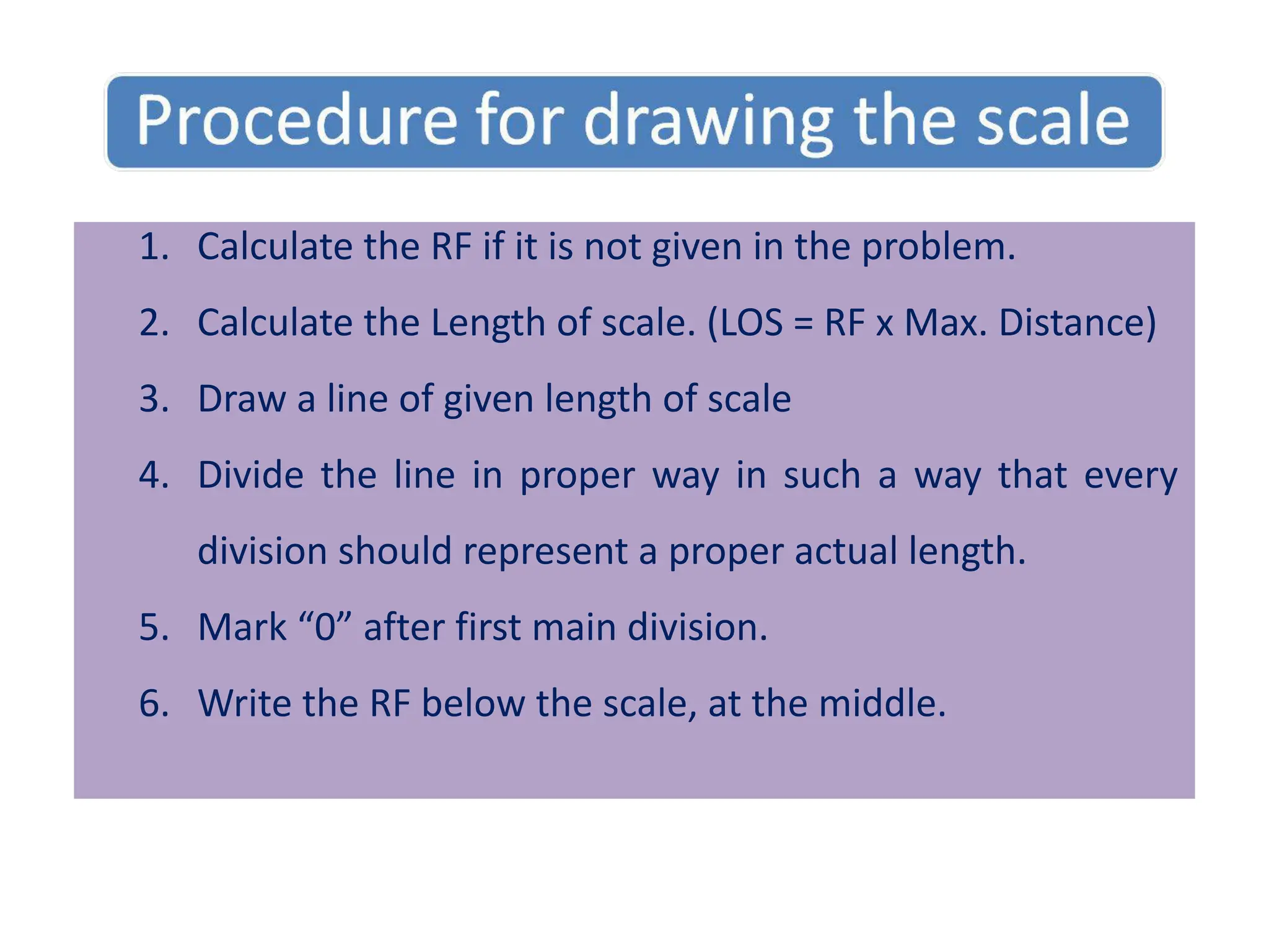
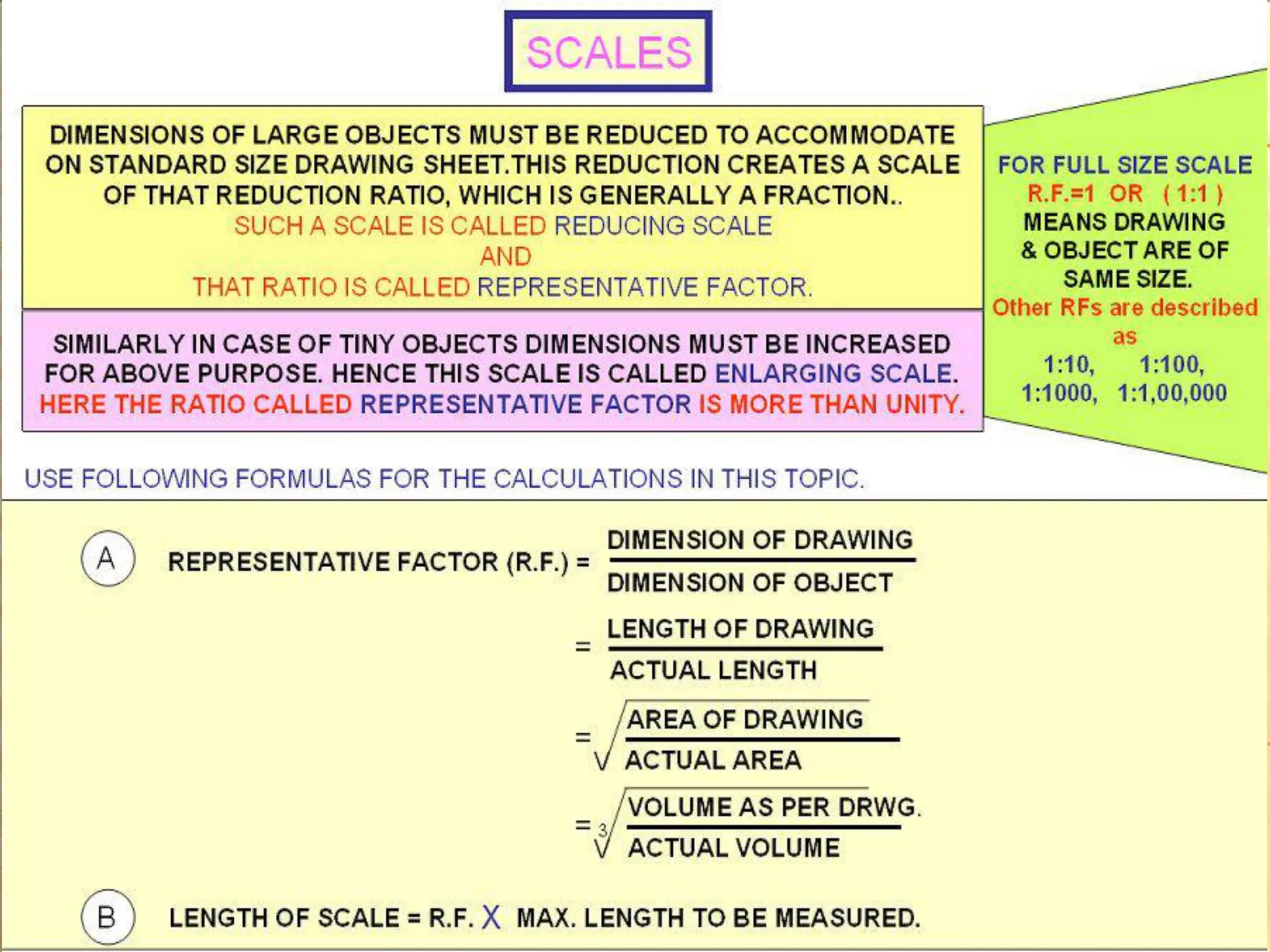
1. Calculate theRF if it is not given in the problem.
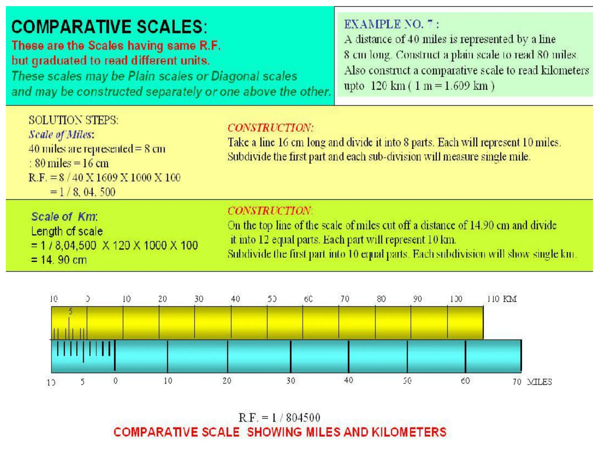
2. Calculate the Length of scale. (LOS = RF x Max. Distance)
3. Draw a line of given length of scale
4. Divide the line in proper way in such a way that every
division should represent a proper actual length.
5. Mark “0” after first main division.
6. Write the RF below the scale, at the middle.
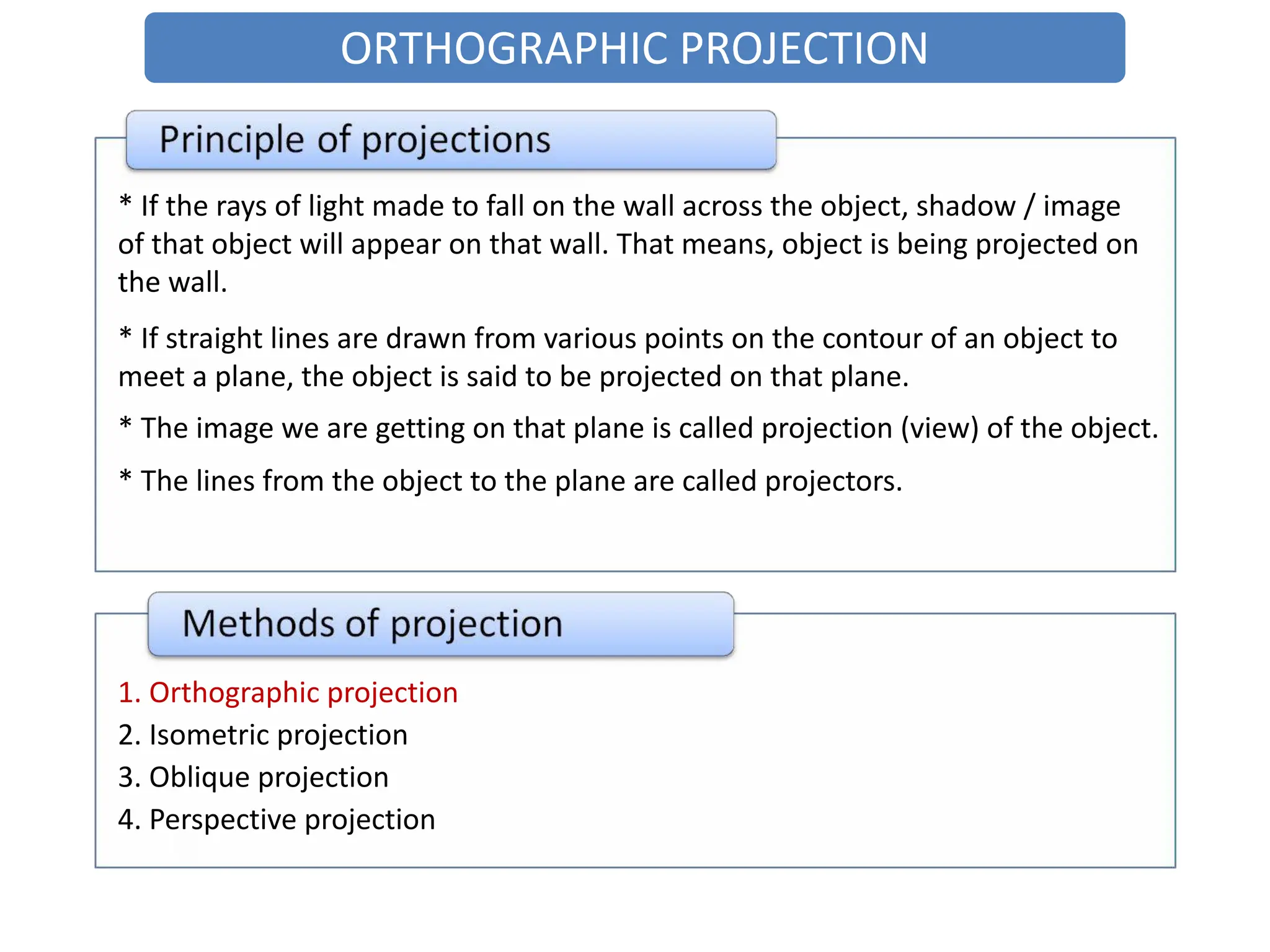
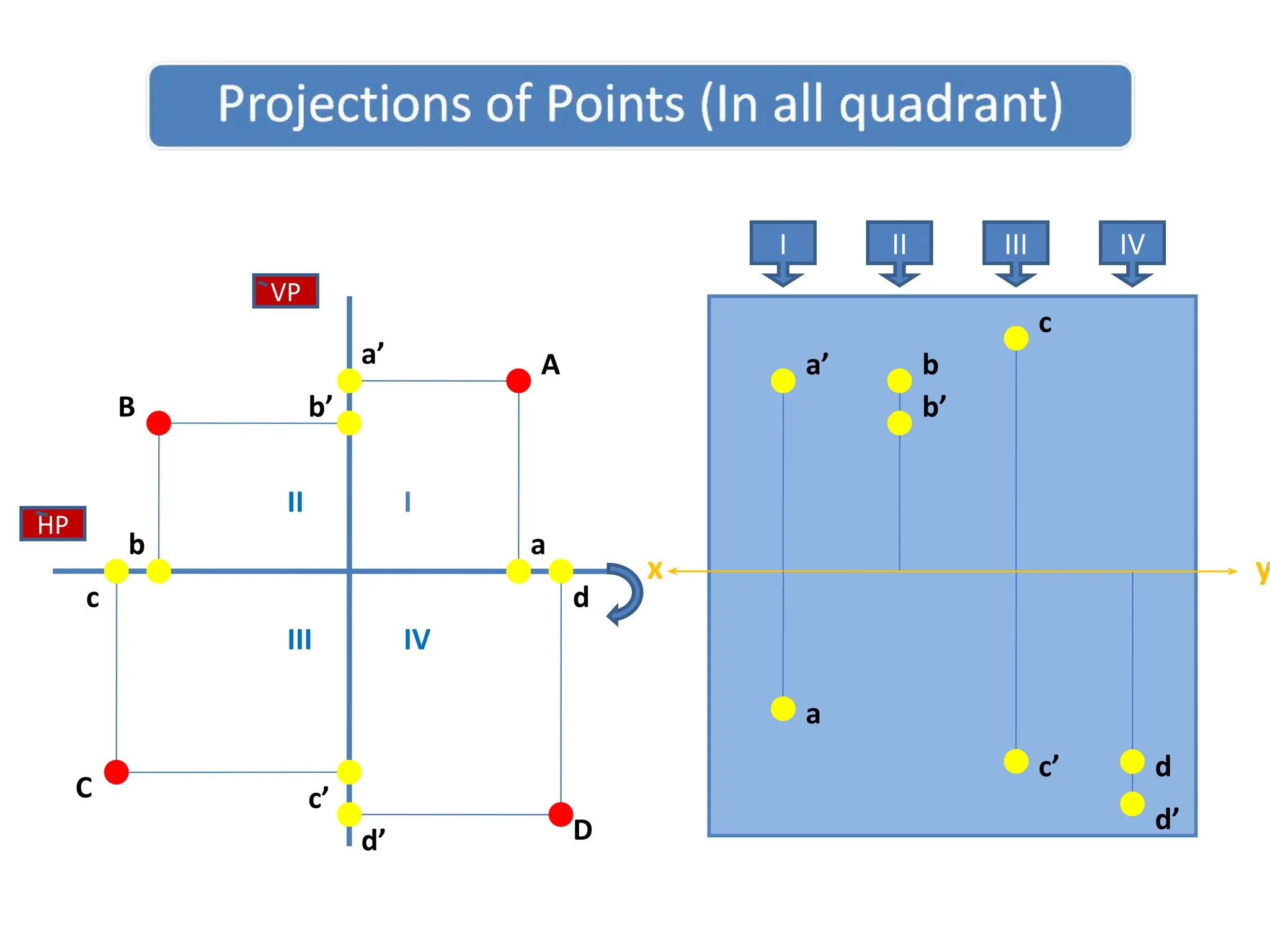
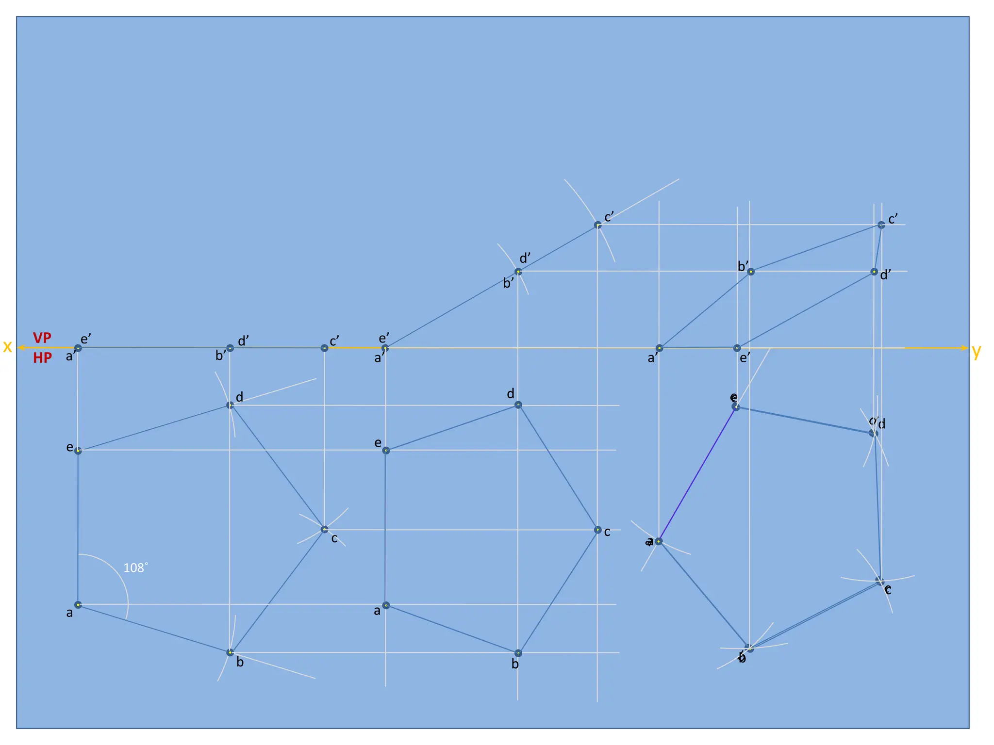
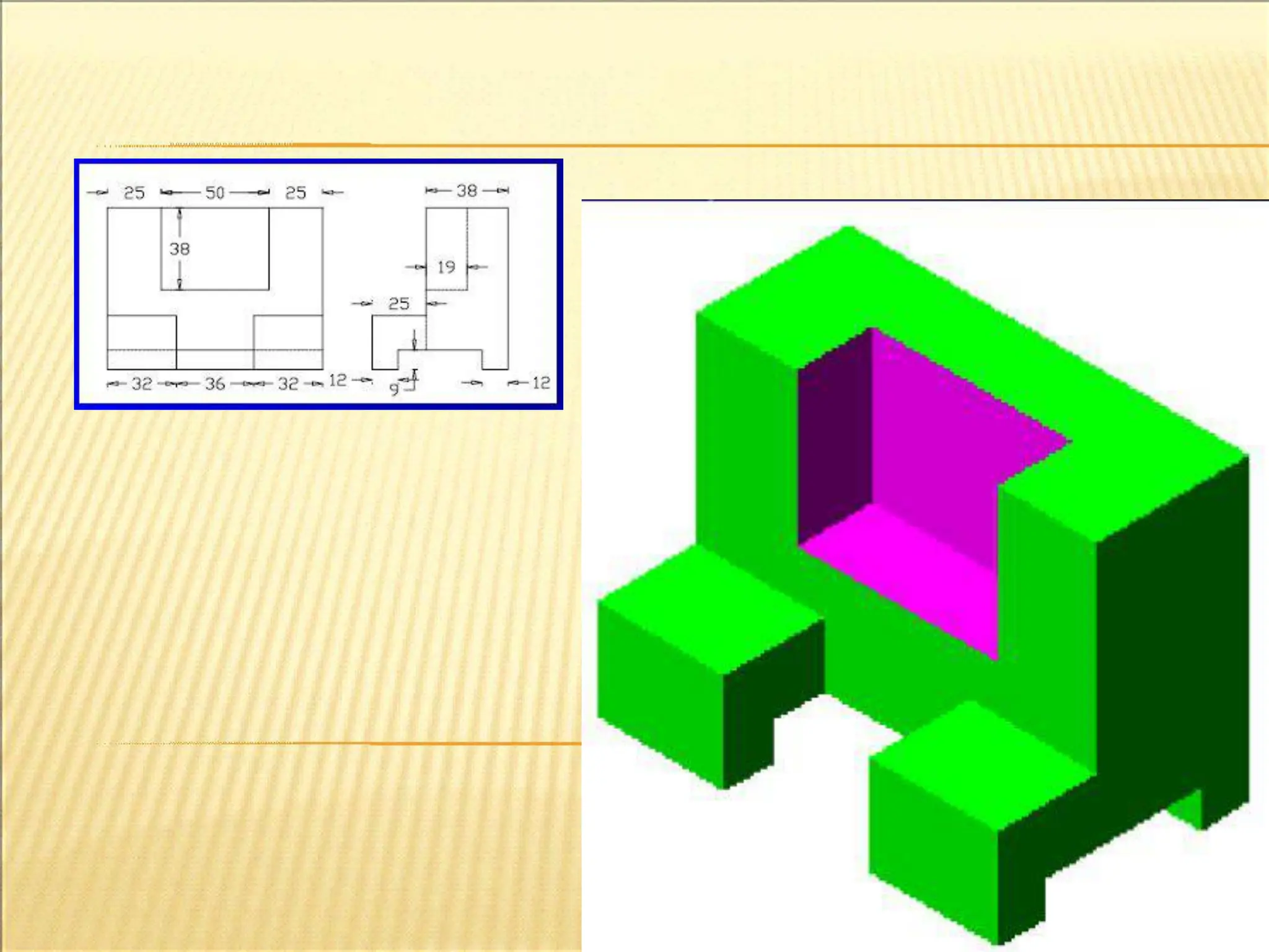
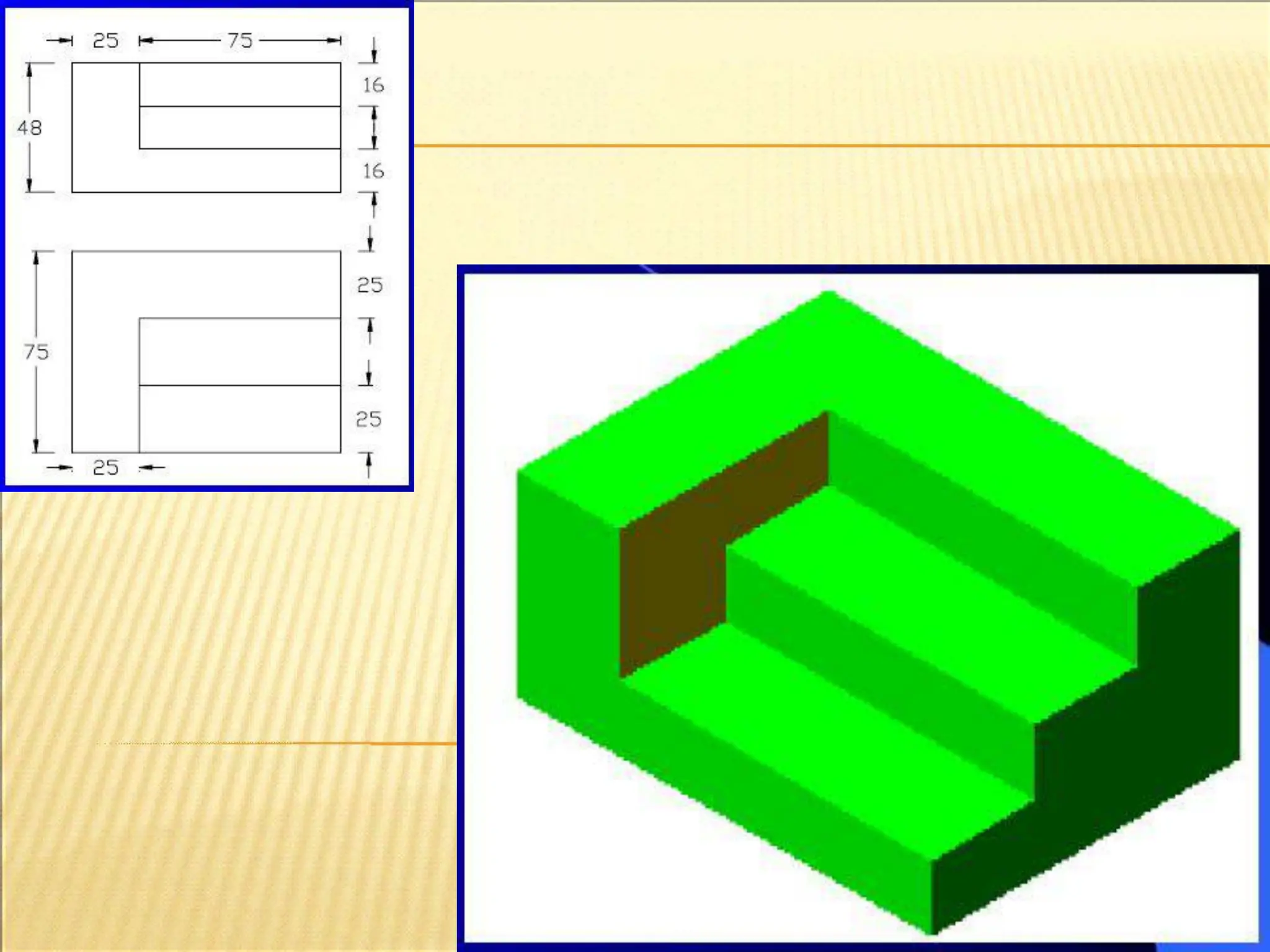
ORTHOGRAPHIC PROJECTION
* Ifthe rays of light made to fall on the wall across the object, shadow / image
of that object will appear on that wall. That means, object is being projected on
the wall.
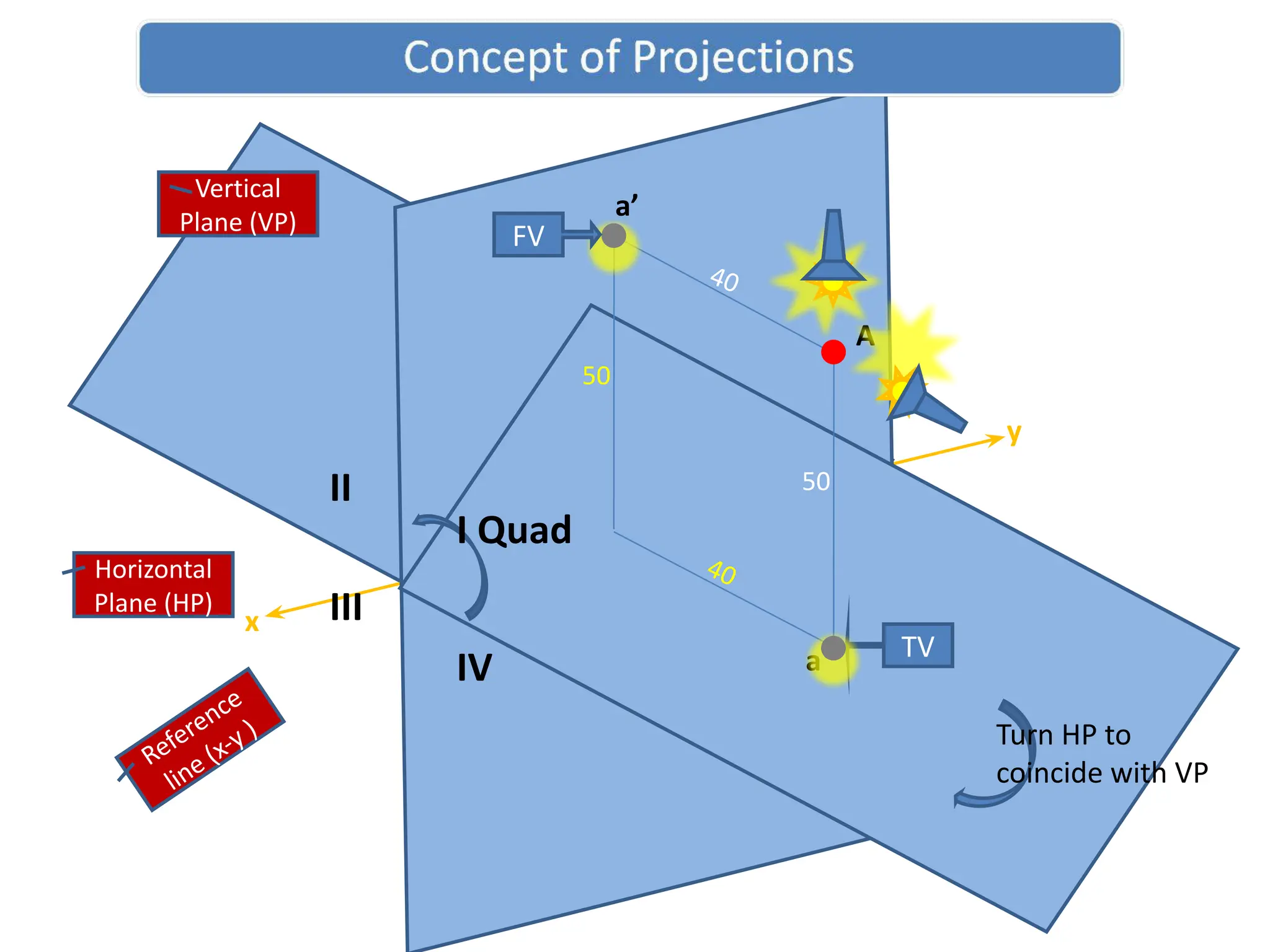
* If straight lines are drawn from various points on the contour of an object to
meet a plane, the object is said to be projected on that plane.
* The image we are getting on that plane is called projection (view) of the object.
* The lines from the object to the plane are called projectors.
1. Orthographic projection
2. Isometric projection
3. Oblique projection
4. Perspective projection
43.
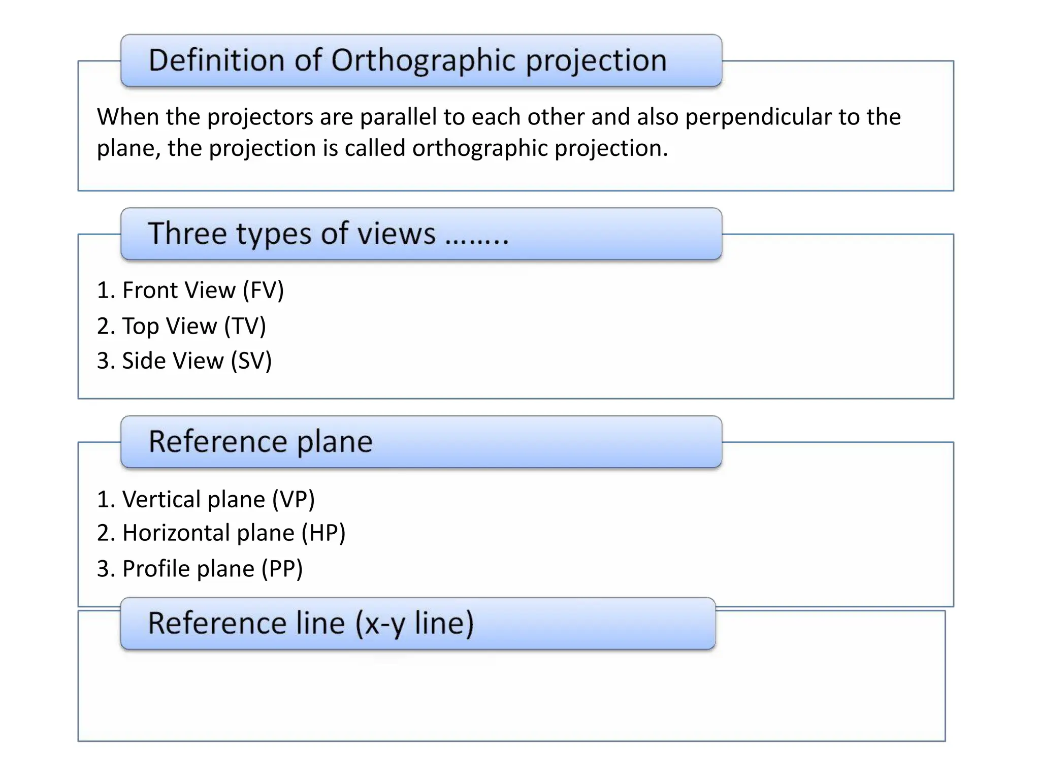
When the projectorsare parallel to each other and also perpendicular to the
plane, the projection is called orthographic projection.
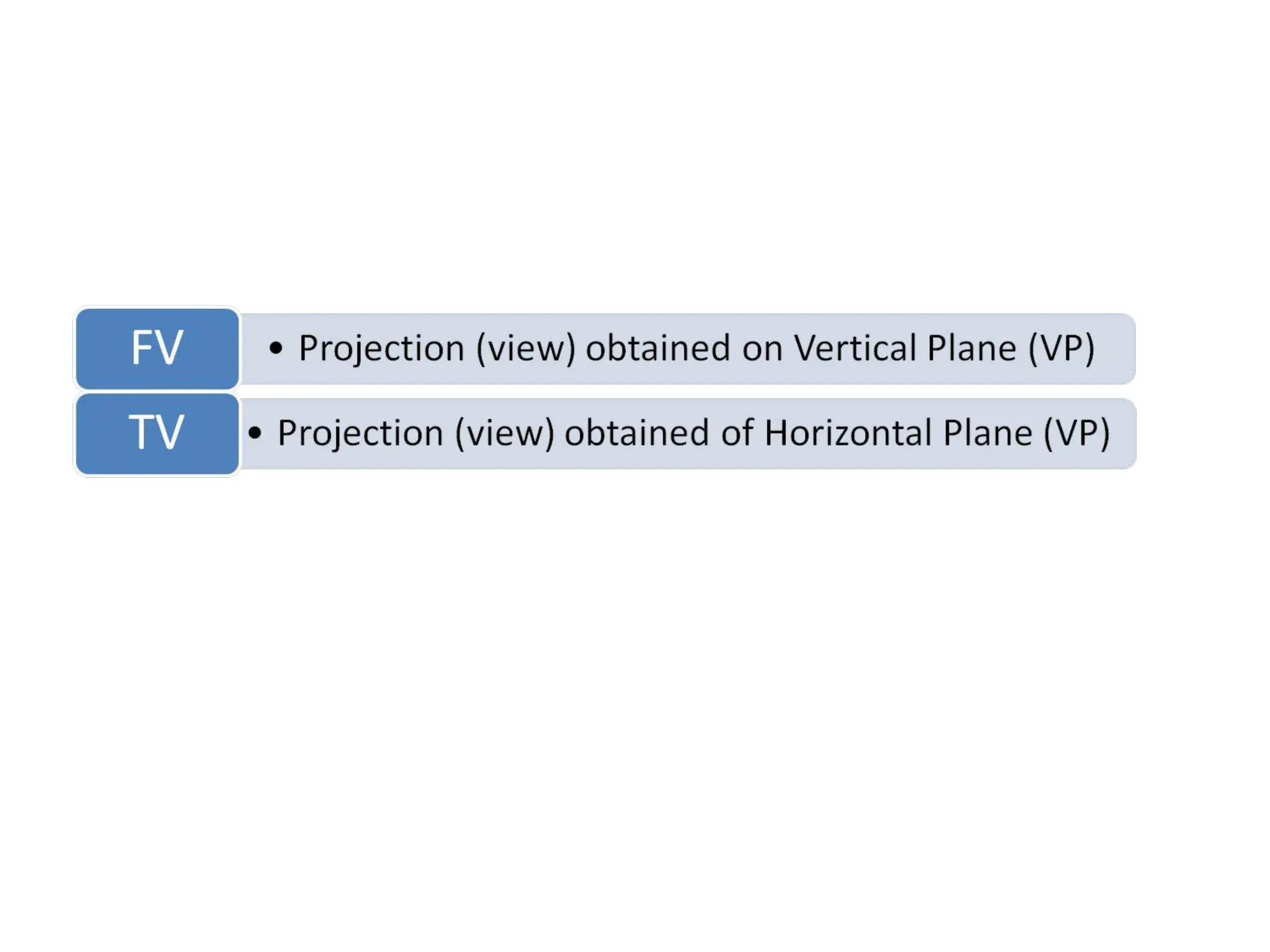
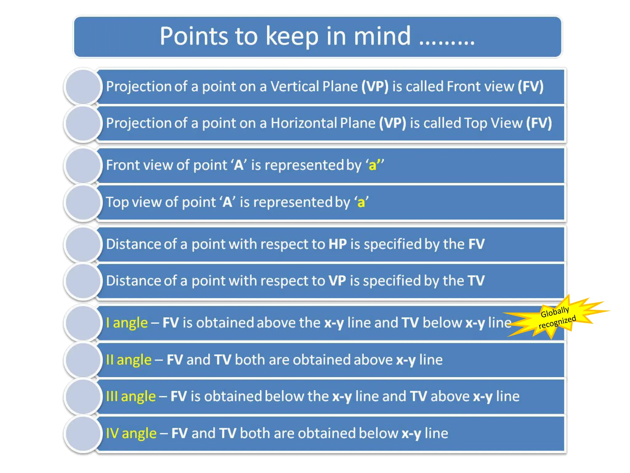
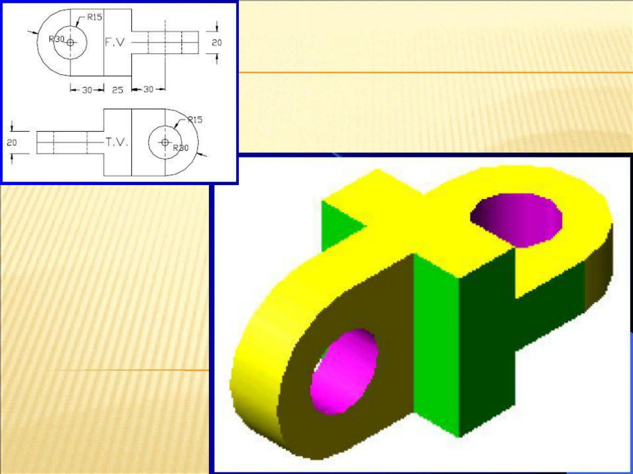
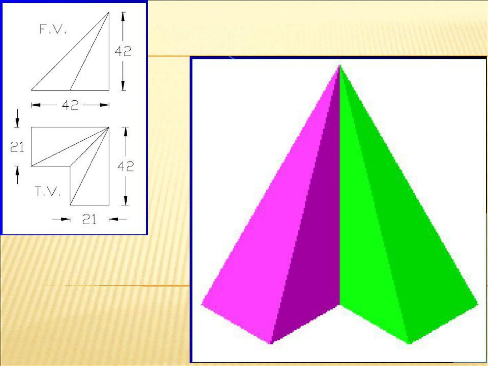
1. Front View (FV)
2. Top View (TV)
3. Side View (SV)
1. Vertical plane (VP)
2. Horizontal plane (HP)
3. Profile plane (PP)
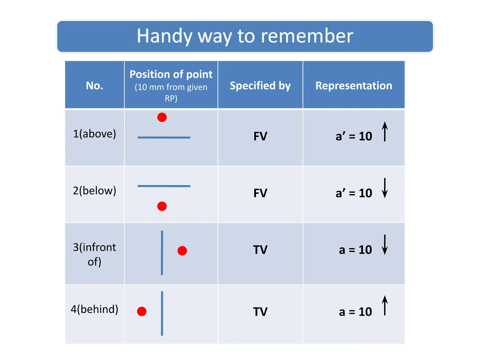
No.
Position of point
(10mm from given
RP)
Specified by Representation
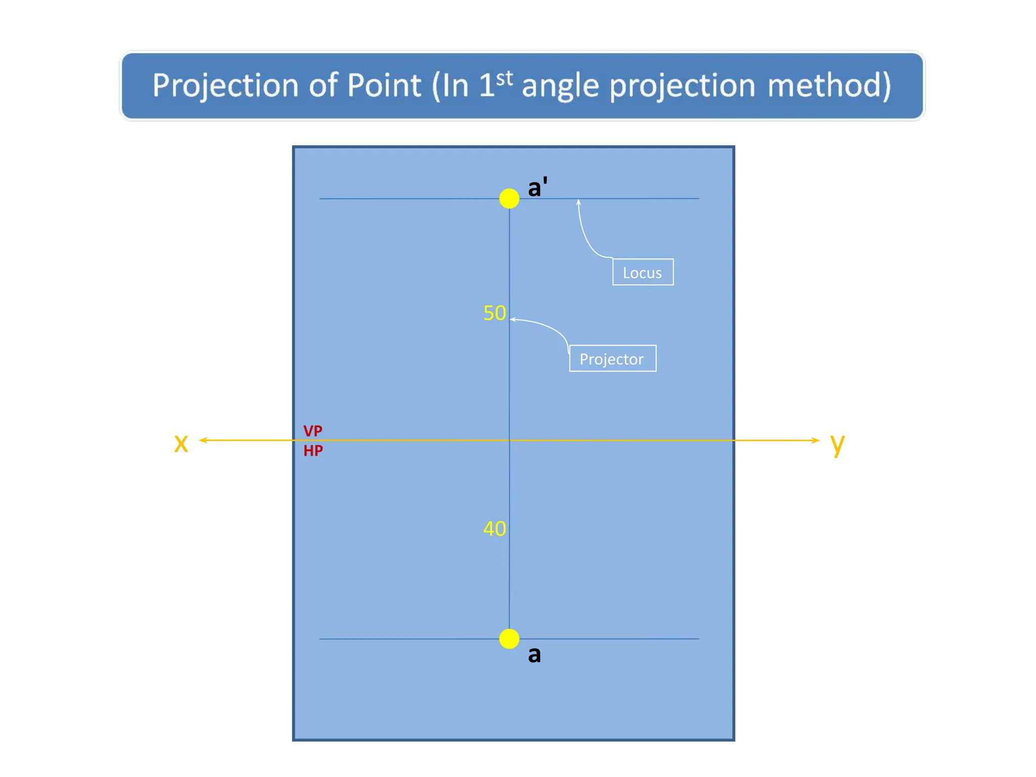
1(above) FV a’ = 10
2(below) FV a’ = 10
3(infront
of)
TV a = 10
4(behind) TV a = 10
50.
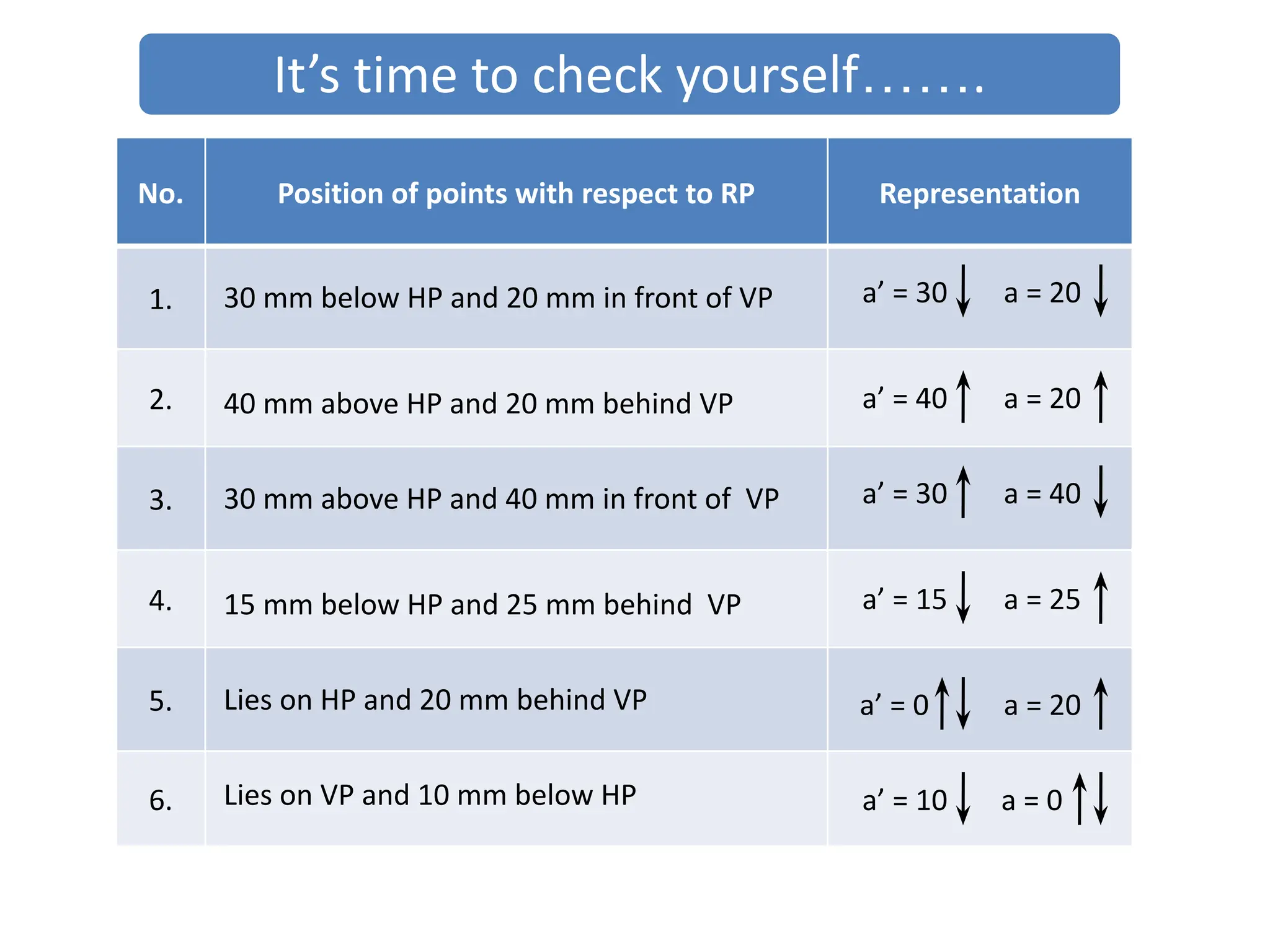
No. Position ofpoints with respect to RP Representation
1.
2.
3.
4.
5.
6.
30 mm below HP and 20 mm in front of VP a’ = 30 a = 20
40 mm above HP and 20 mm behind VP a’ = 40 a = 20
30 mm above HP and 40 mm in front of VP a’ = 30 a = 40
15 mm below HP and 25 mm behind VP a’ = 15 a = 25
Lies on HP and 20 mm behind VP a’ = 0 a = 20
Lies on VP and 10 mm below HP a’ = 10 a = 0
It’s time to check yourself…….
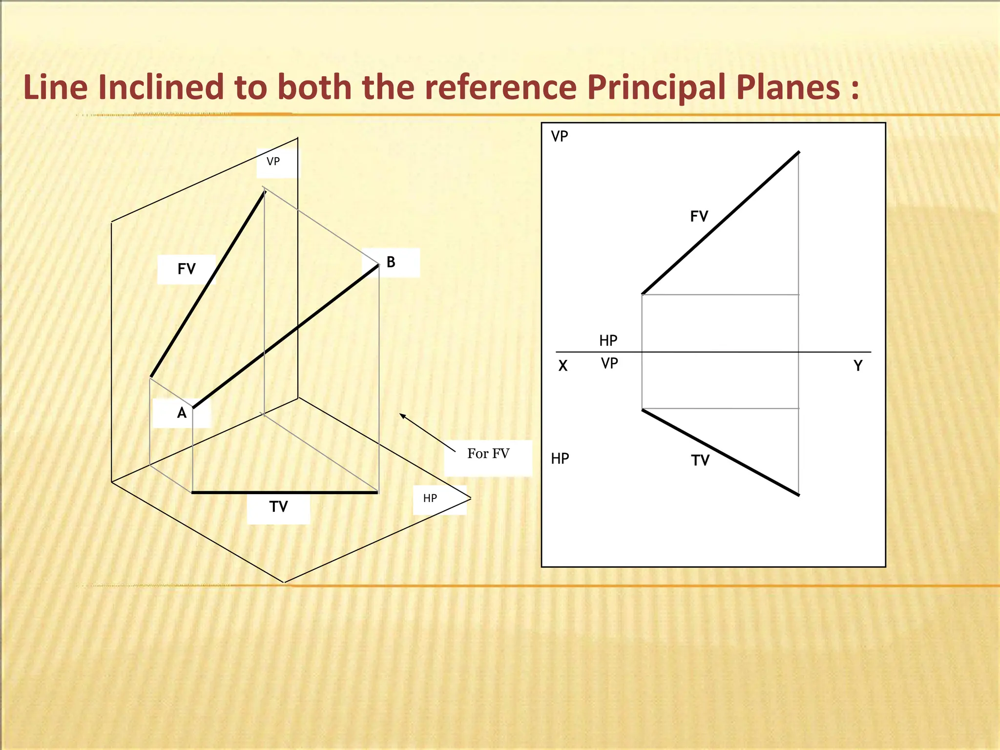
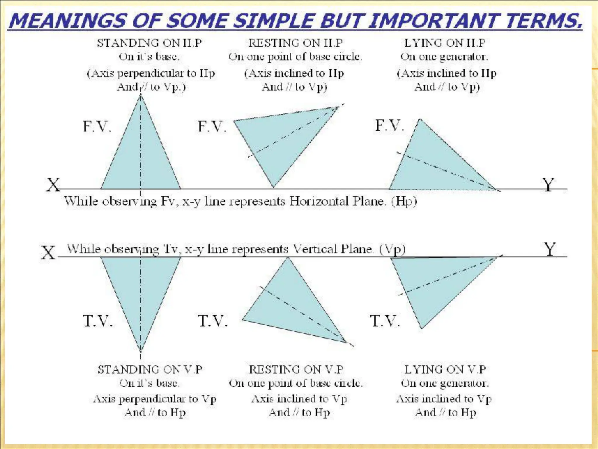
Lines in spaceare of three types considering their position with
respect to principal planes :
1) Line parallel to both HP and VP.
2) Line perpendicular to one and parallel to other.
3) Line parallel to one and inclined to other.
4) Line inclined to both principal planes.
53.
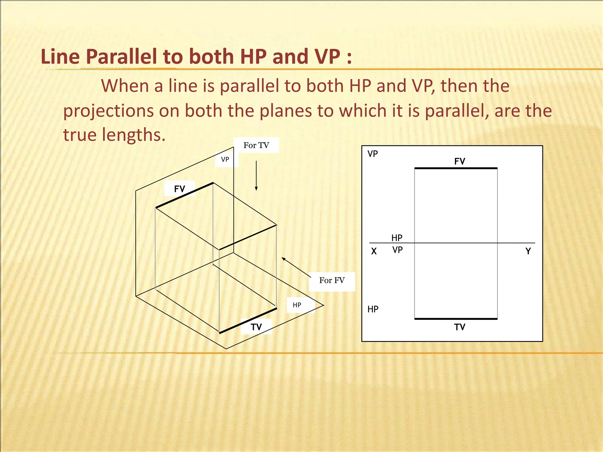
Line Parallel toboth HP and VP :
When a line is parallel to both HP and VP, then the
projections on both the planes to which it is parallel, are the
true lengths.
VP
HP
HP
VP
For FV
For TV
FV
TV
FV
TV
X Y
HP
VP
54.
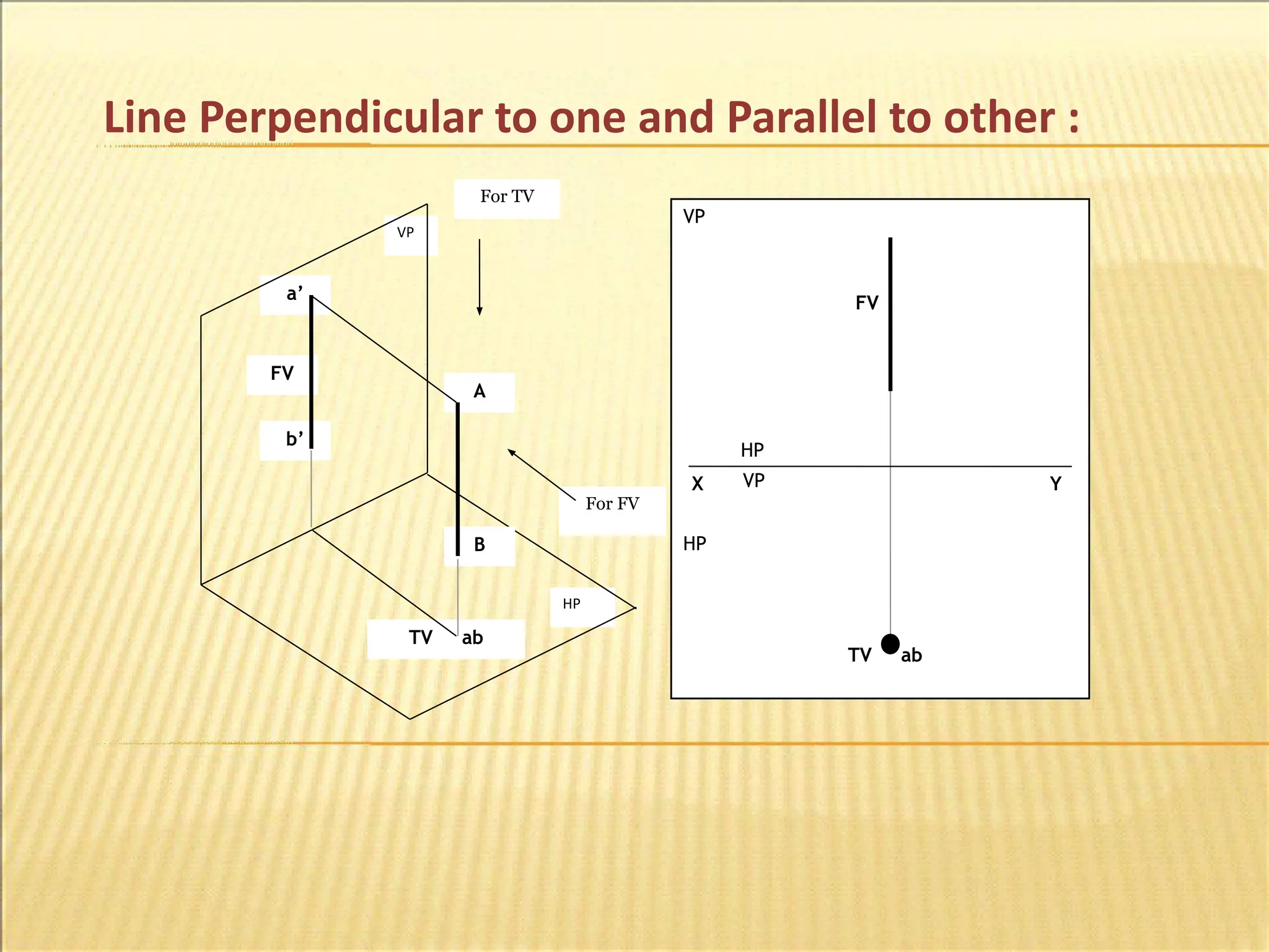
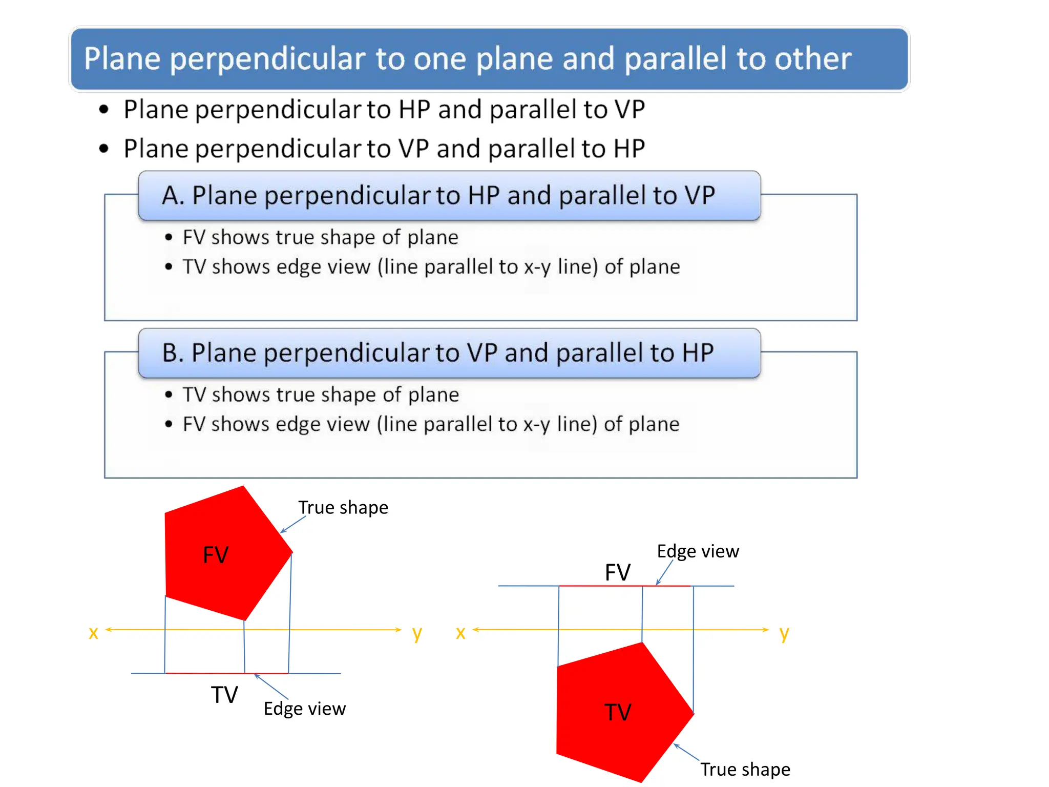
Line Perpendicular toone and Parallel to other :
VP
HP
HP
VP
For FV
For TV
A
B
a’
b’
TV ab
FV
FV
TV ab
X Y
HP
VP
55.
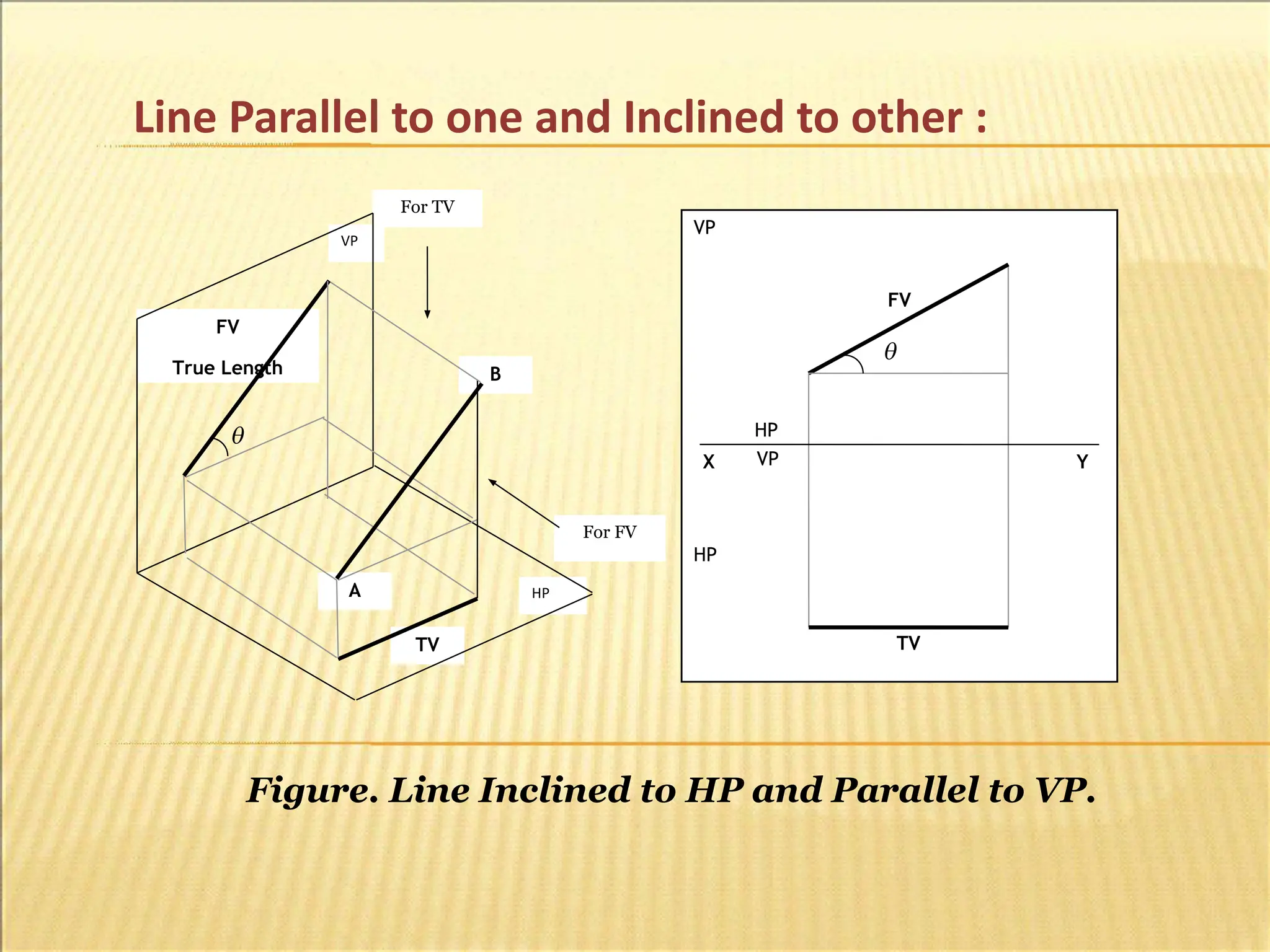
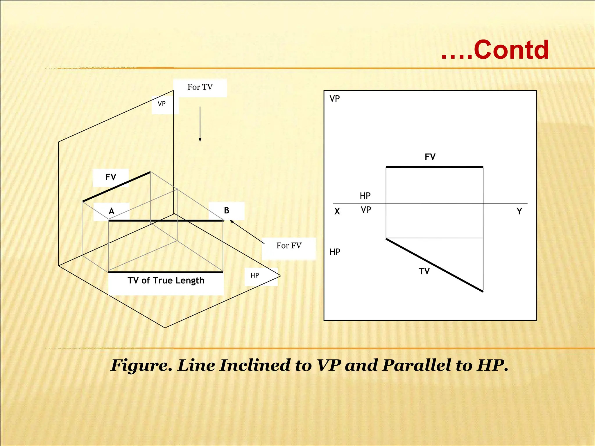
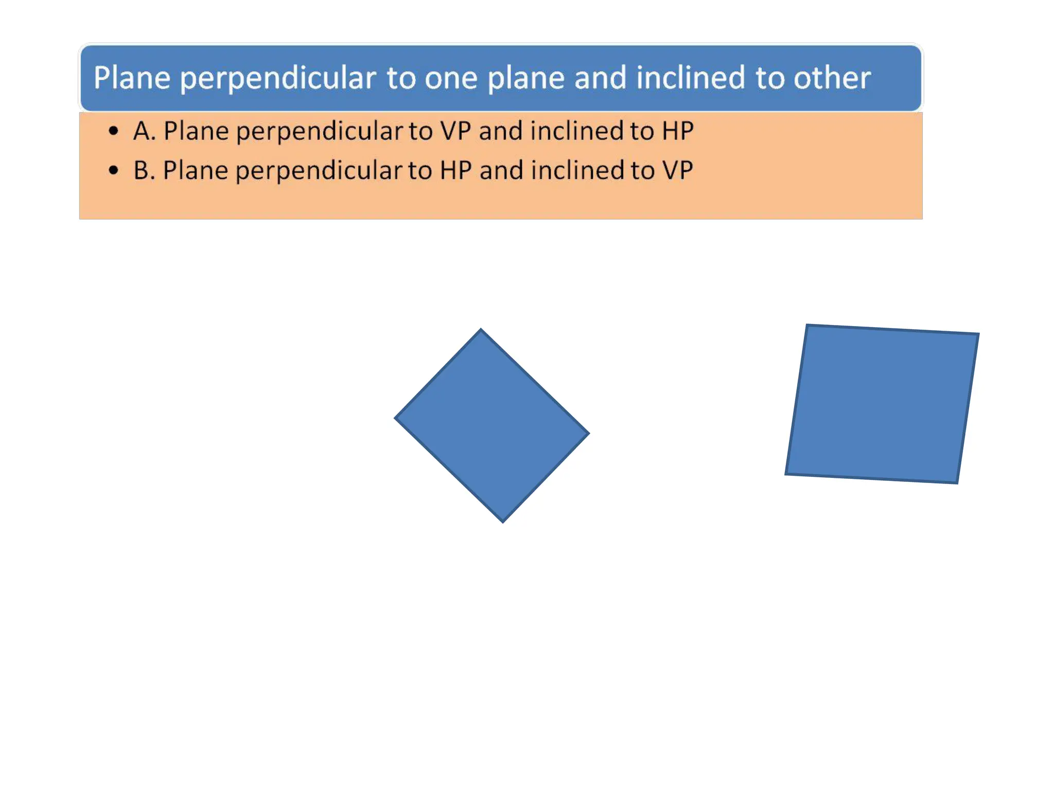
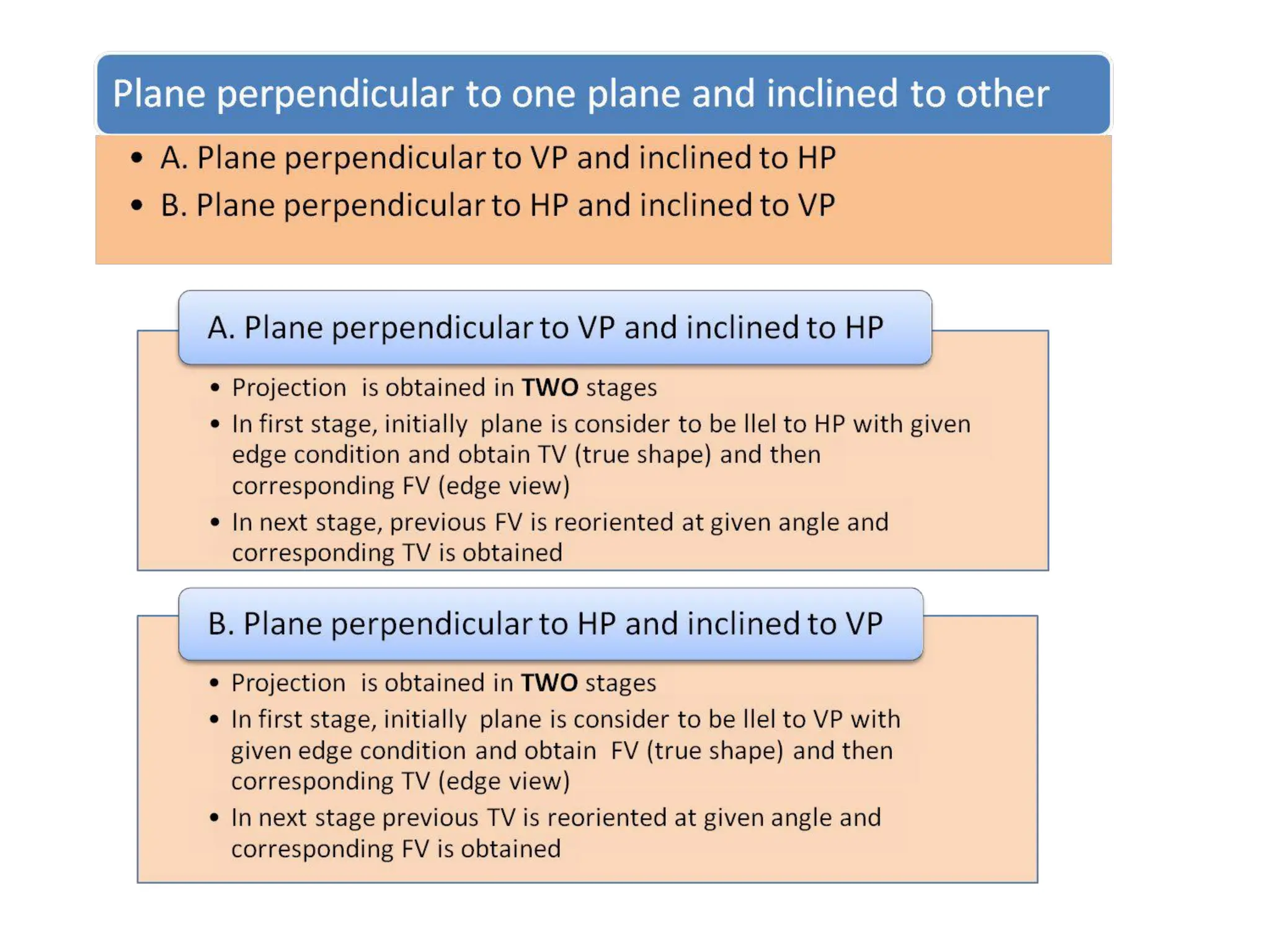
Line Parallel toone and Inclined to other :
VP
HP
HP
VP
For FV
For TV
FV
True Length
TV
FV
TV
X Y
HP
VP
A
B
Figure. Line Inclined to HP and Parallel to VP.
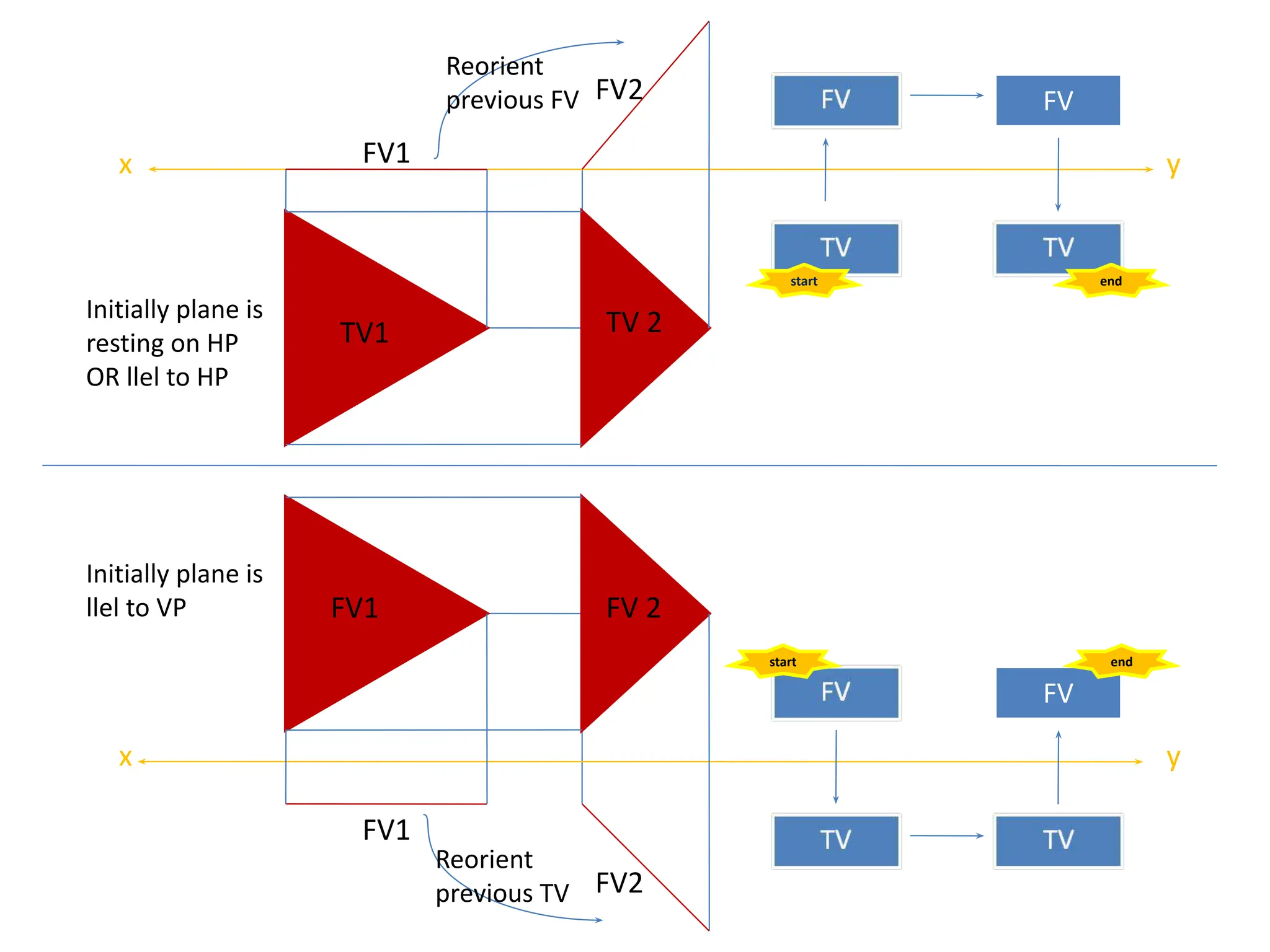
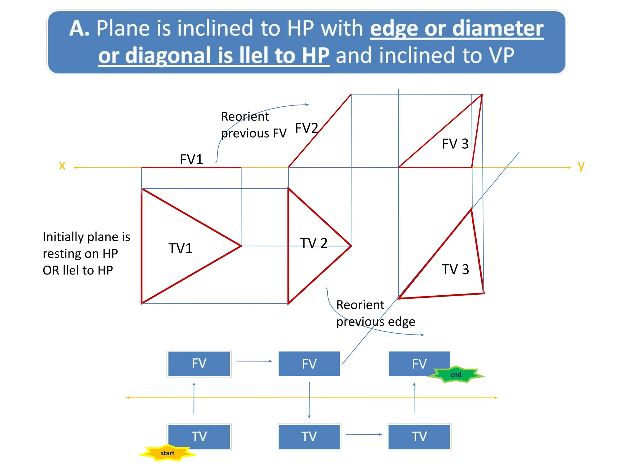
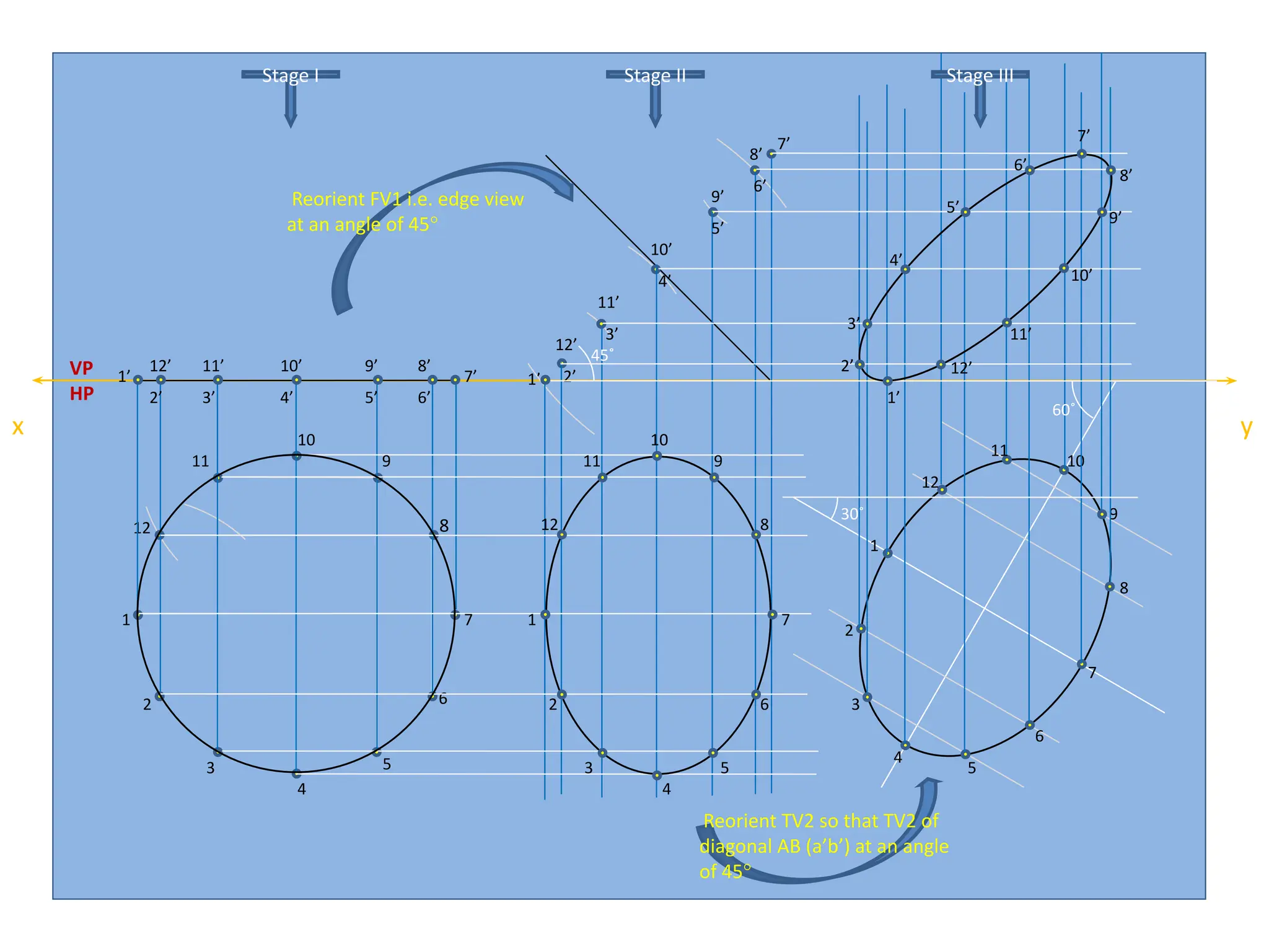
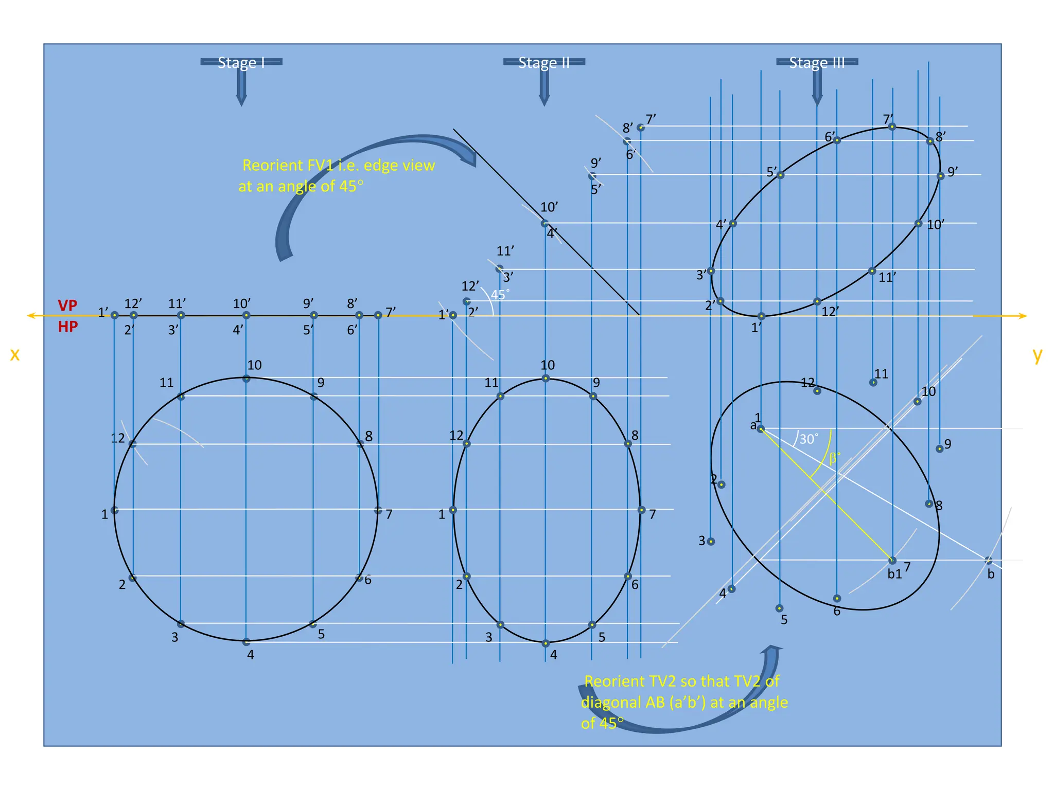
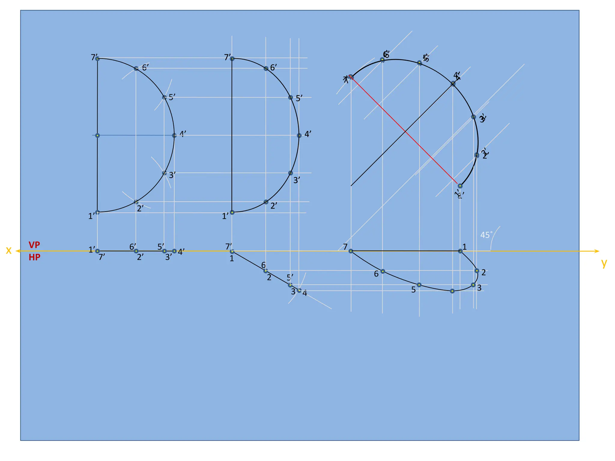
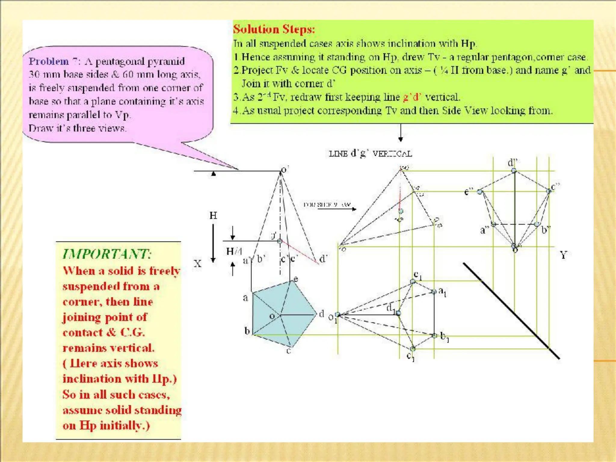
Initially plane is
restingon HP
OR llel to HP
TV1
FV1
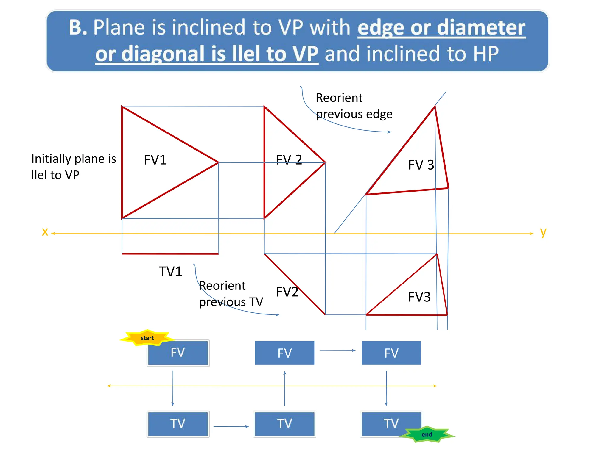
Initially plane is
llel to VP
FV
FV
FV1
FV1
FV2
FV2
x y
x y
Reorient
previous FV
Reorient
previous TV
FV 2
TV 2
start
start end
end
66.
Initially plane is
restingon HP
OR llel to HP
TV1
FV1
FV2
x y
Reorient
previous FV
TV 2
Reorient
previous edge
TV 3
FV 3
FV
start
FV
end
67.
FV1
x y
FV 2
Initiallyplane is
llel to VP
Reorient
previous TV
Reorient
previous edge
FV 3
FV2 FV3
FV
start
FV
end
TV1
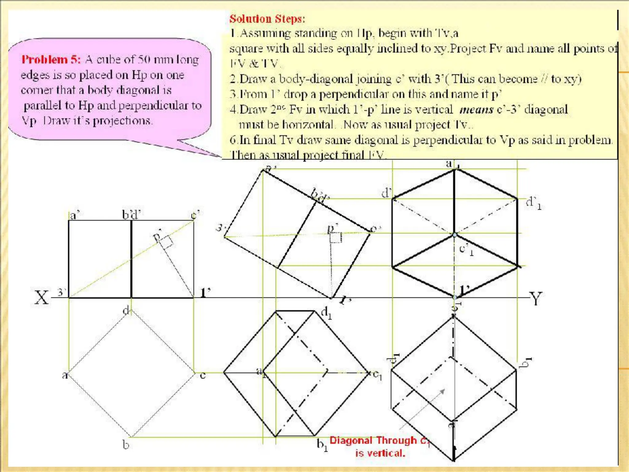
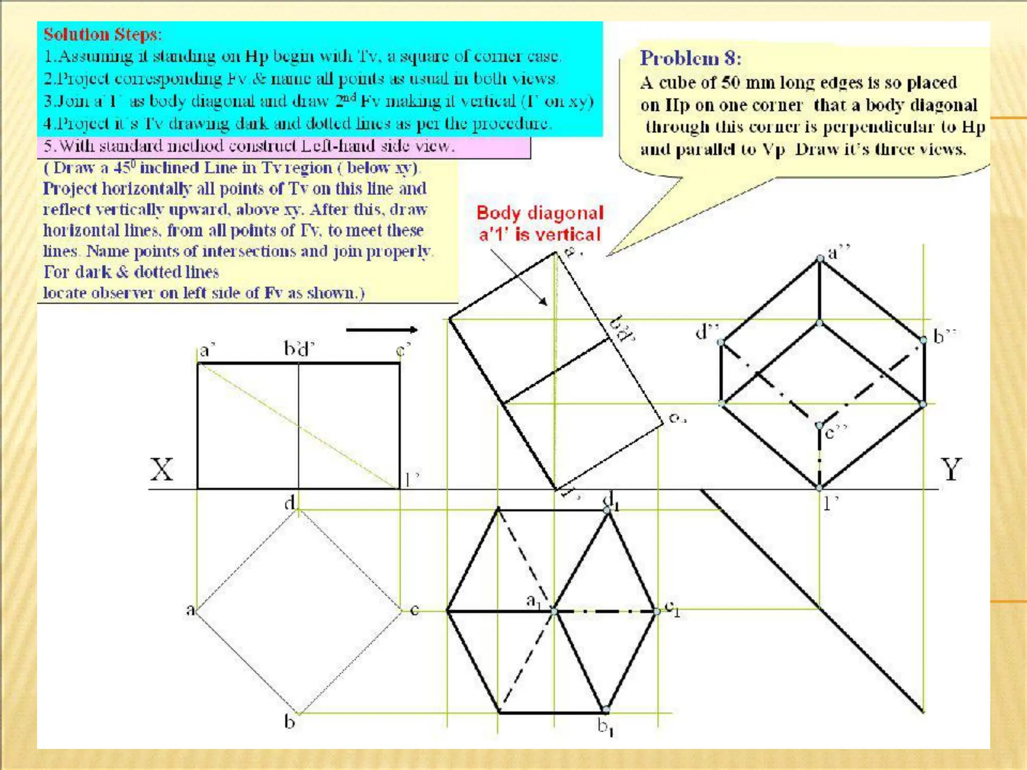
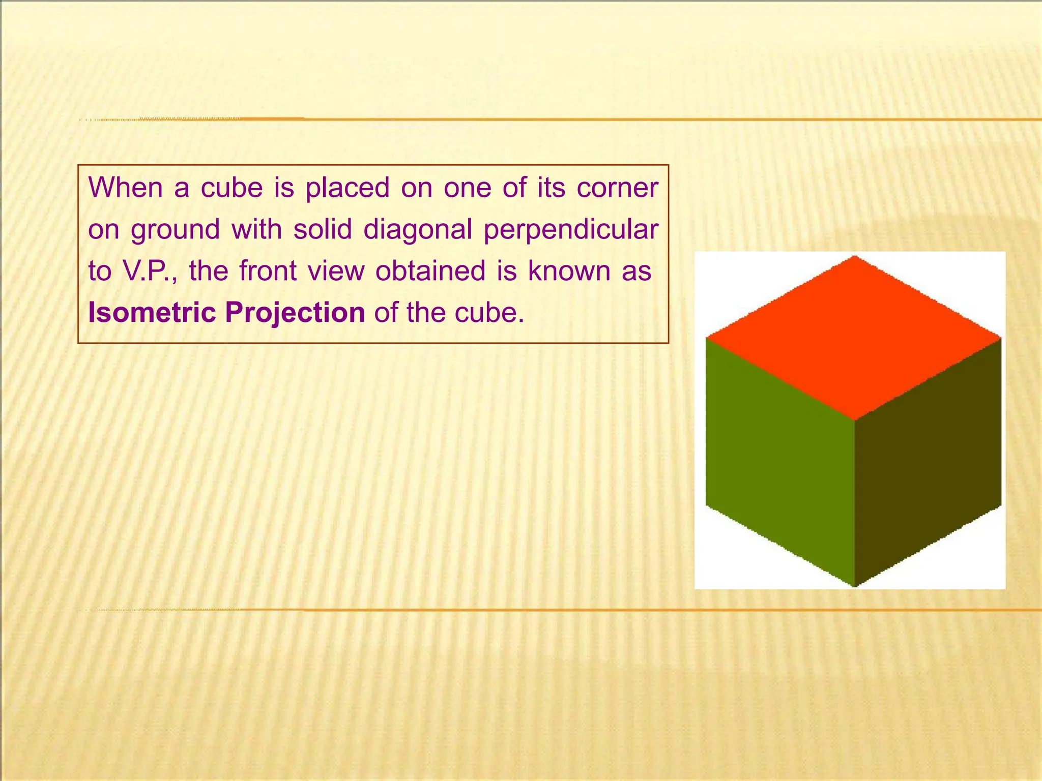
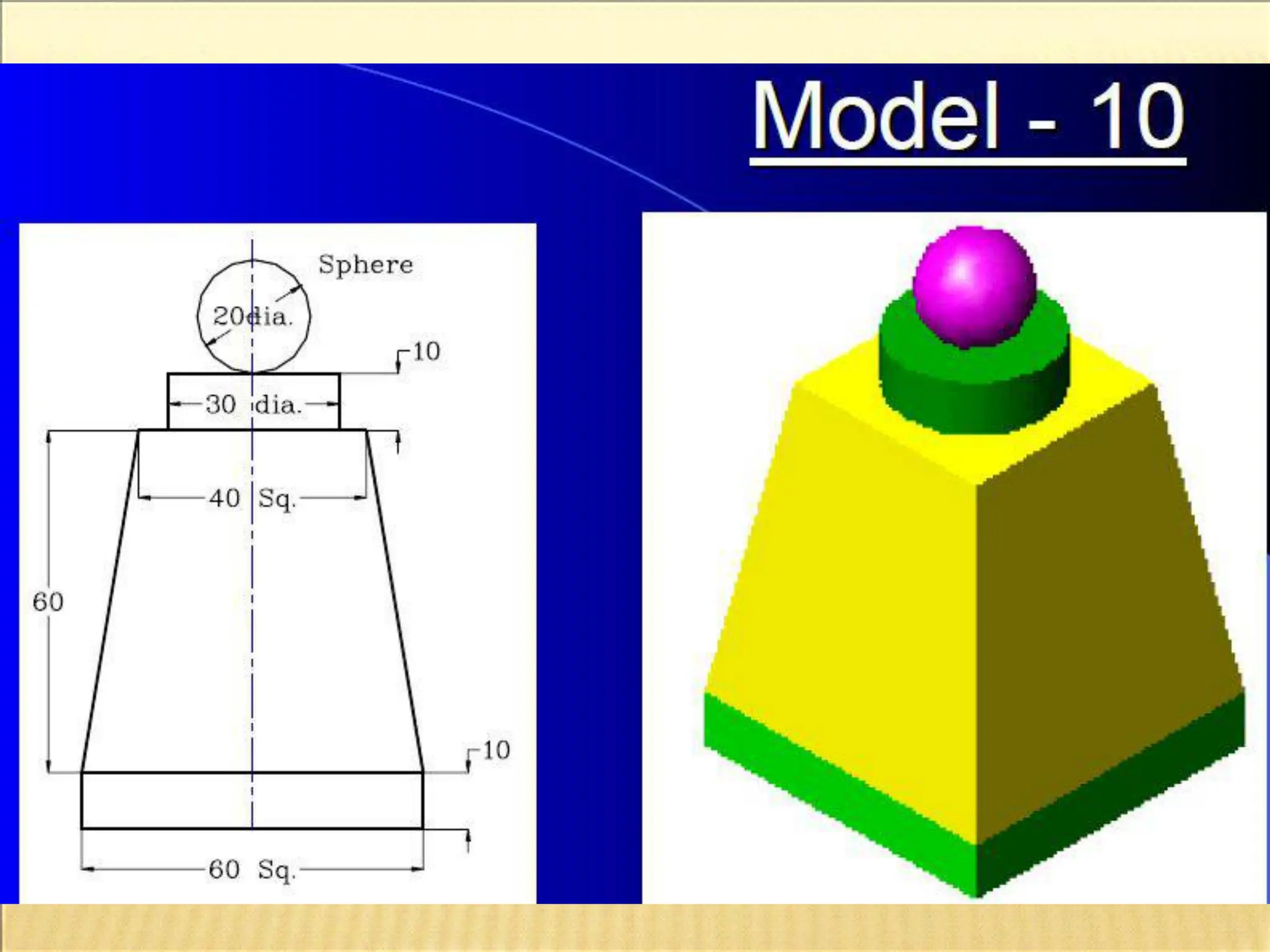
When a cubeis placed on one of its corner
on ground with solid diagonal perpendicular
to V.P., the front view obtained is known as
Isometric Projection of the cube.
108.
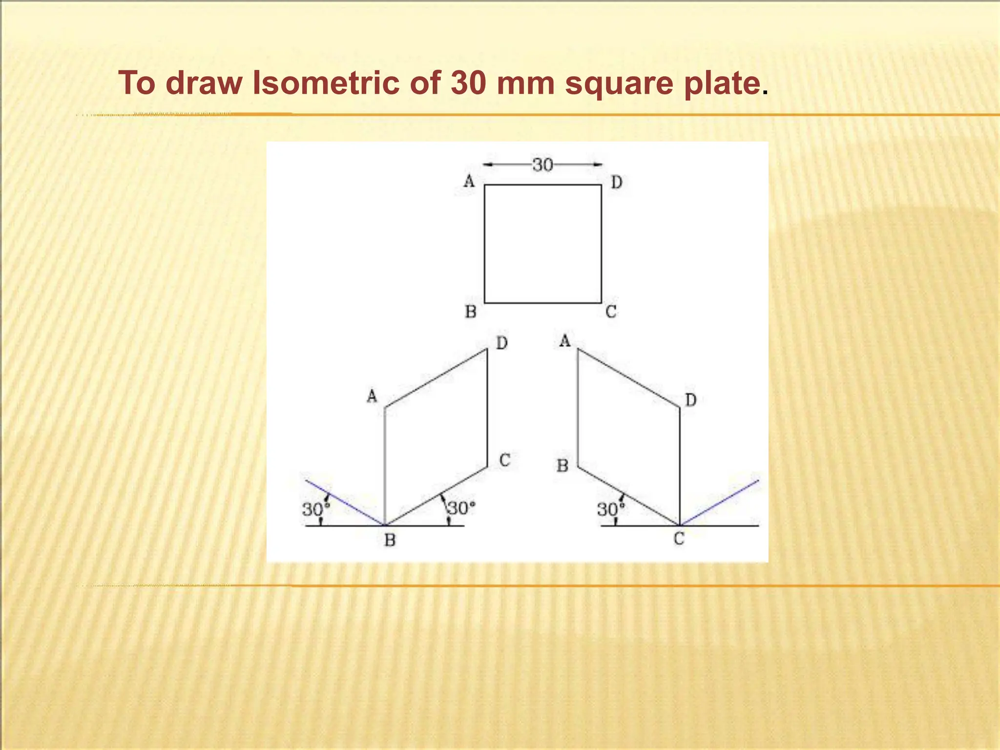
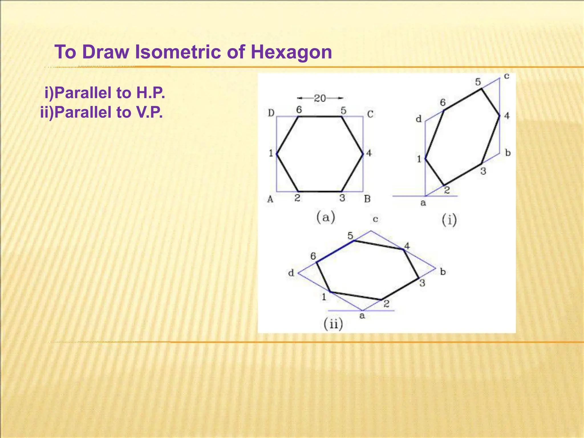
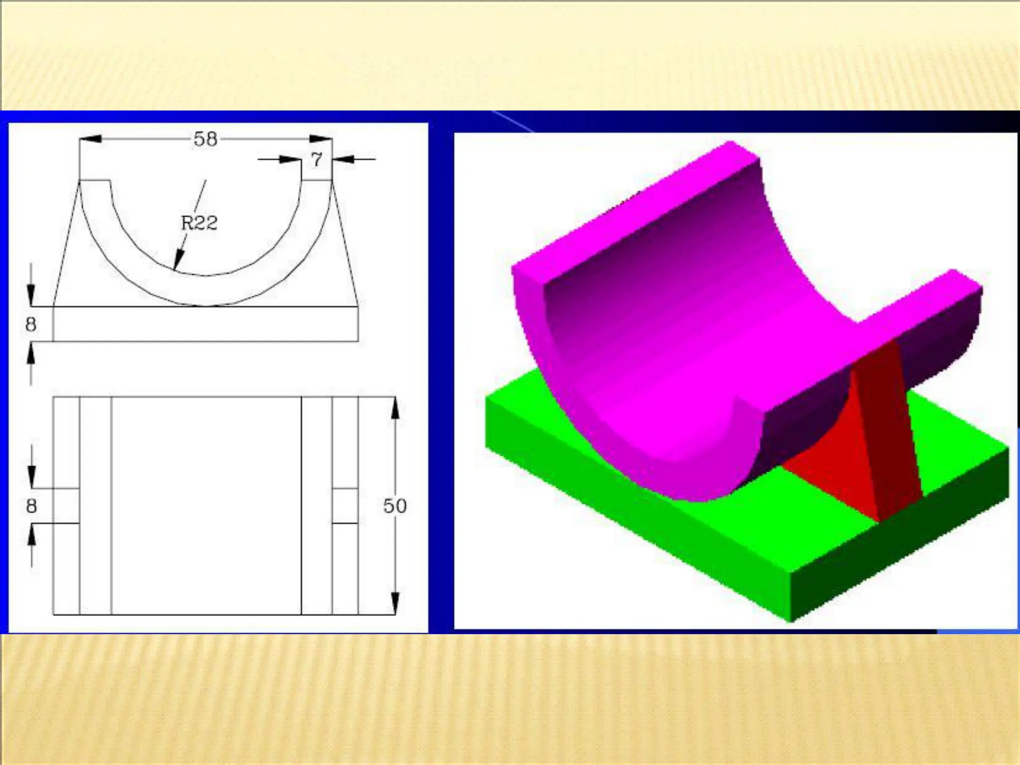
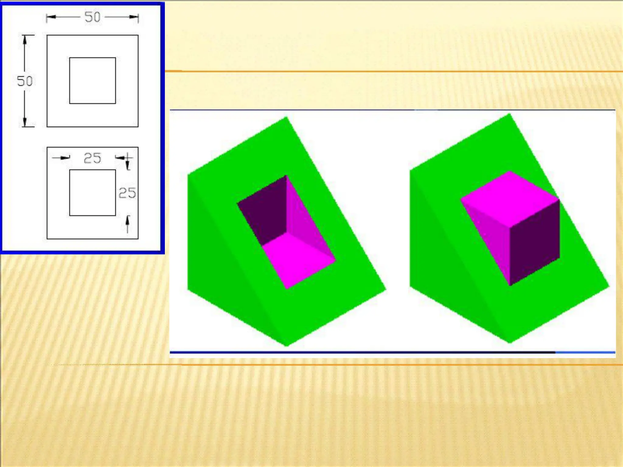
Isometric Axes, Lines& Planes:
Iso. View: For simplicity actual/True lengths are considered
and the radius of sphere is taken as 11/9*radius.
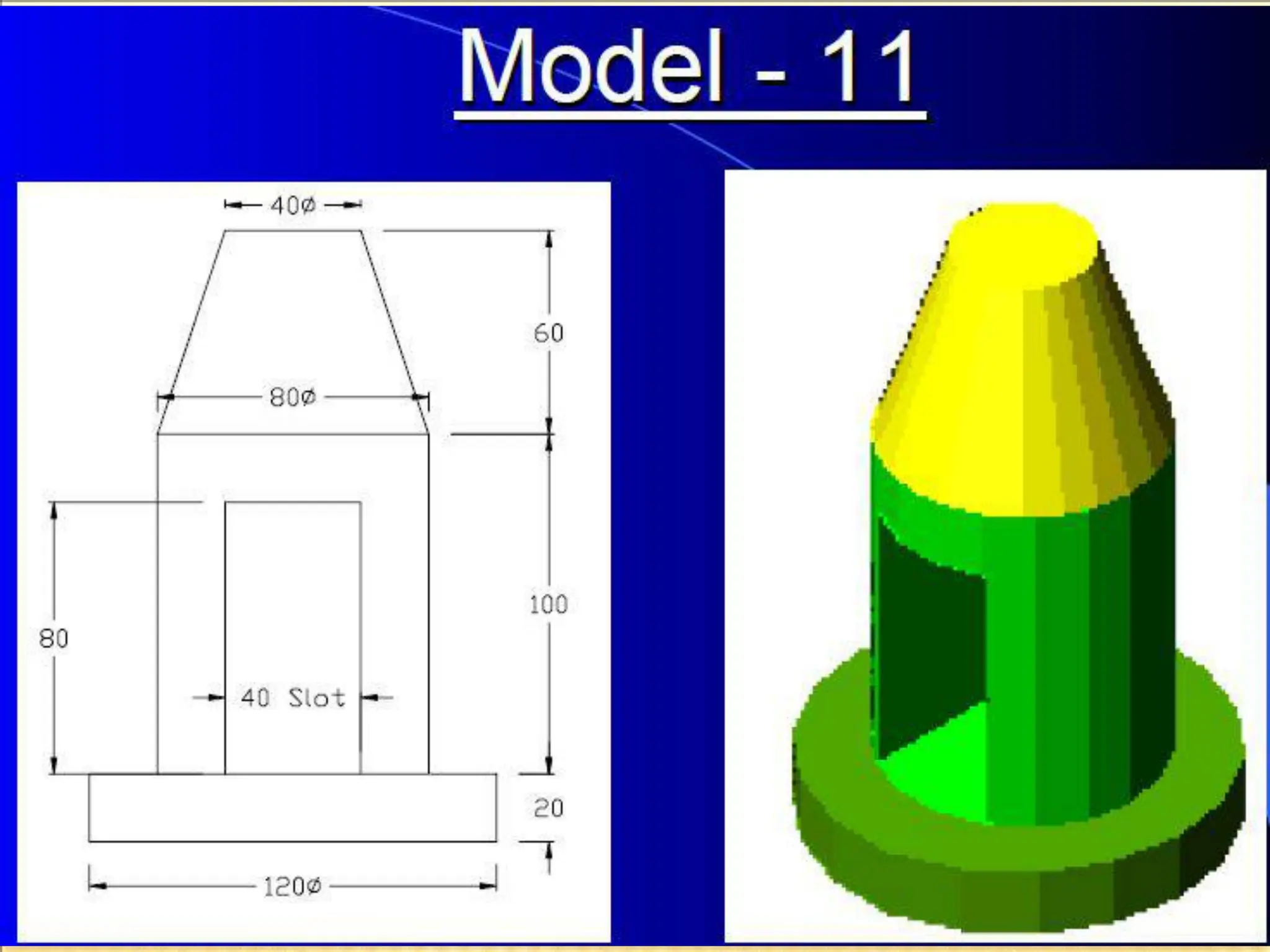
The ratio, Isometric Length / True Length = 9/11 approx.
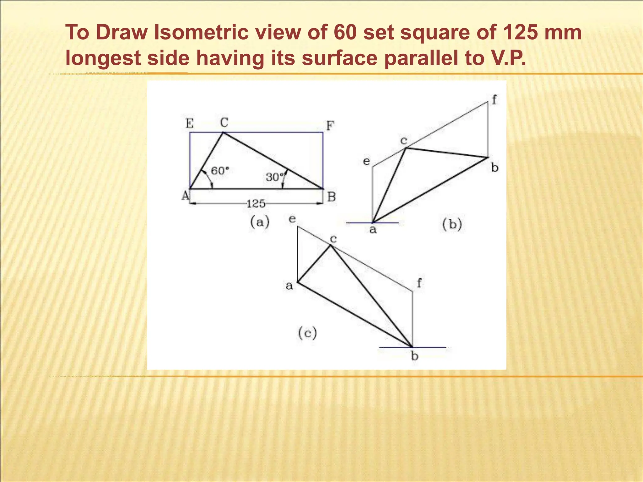
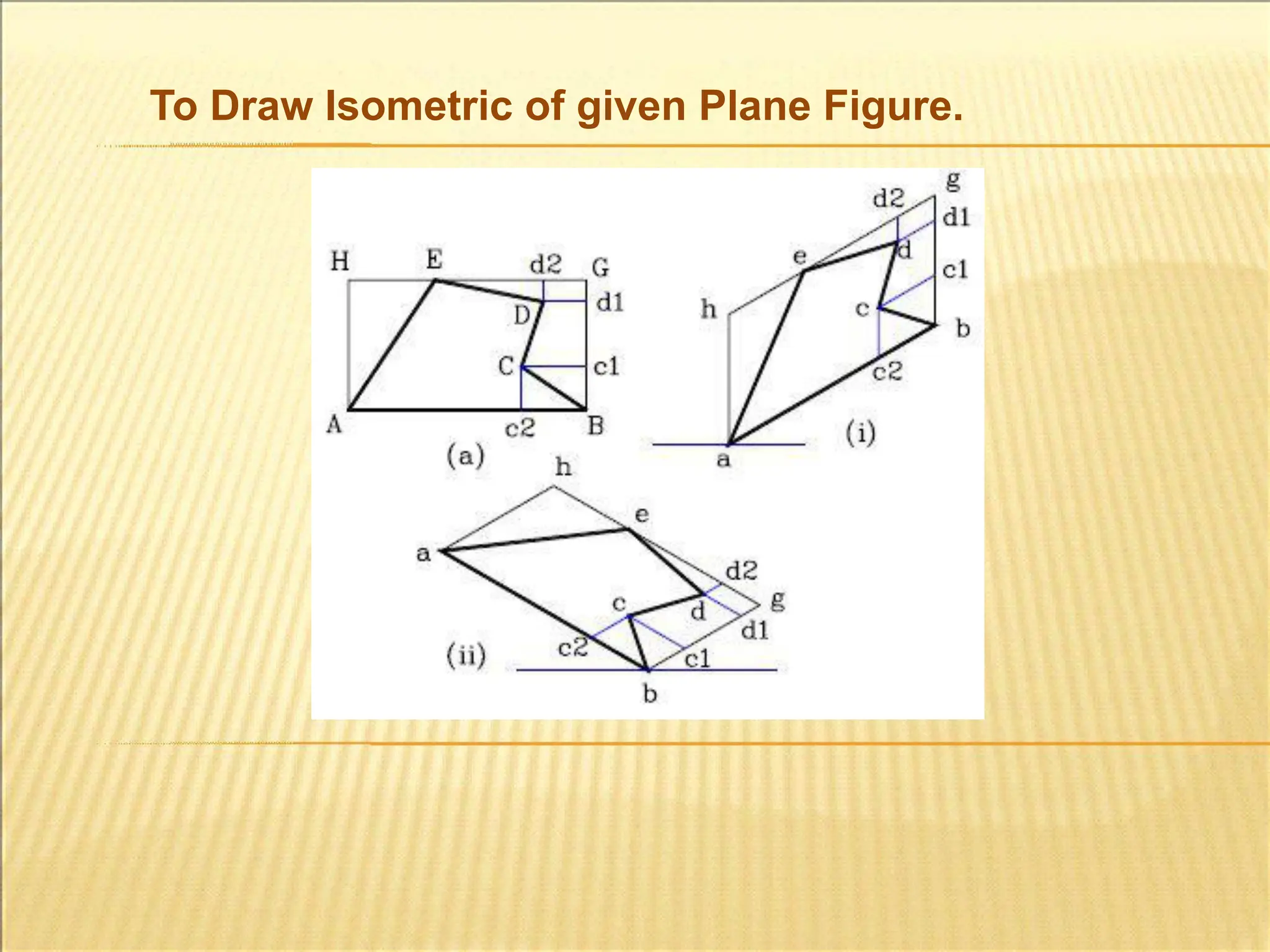
It is necessary that while drawing Iso. Projections, true
lengths should be converted toIso. Length.
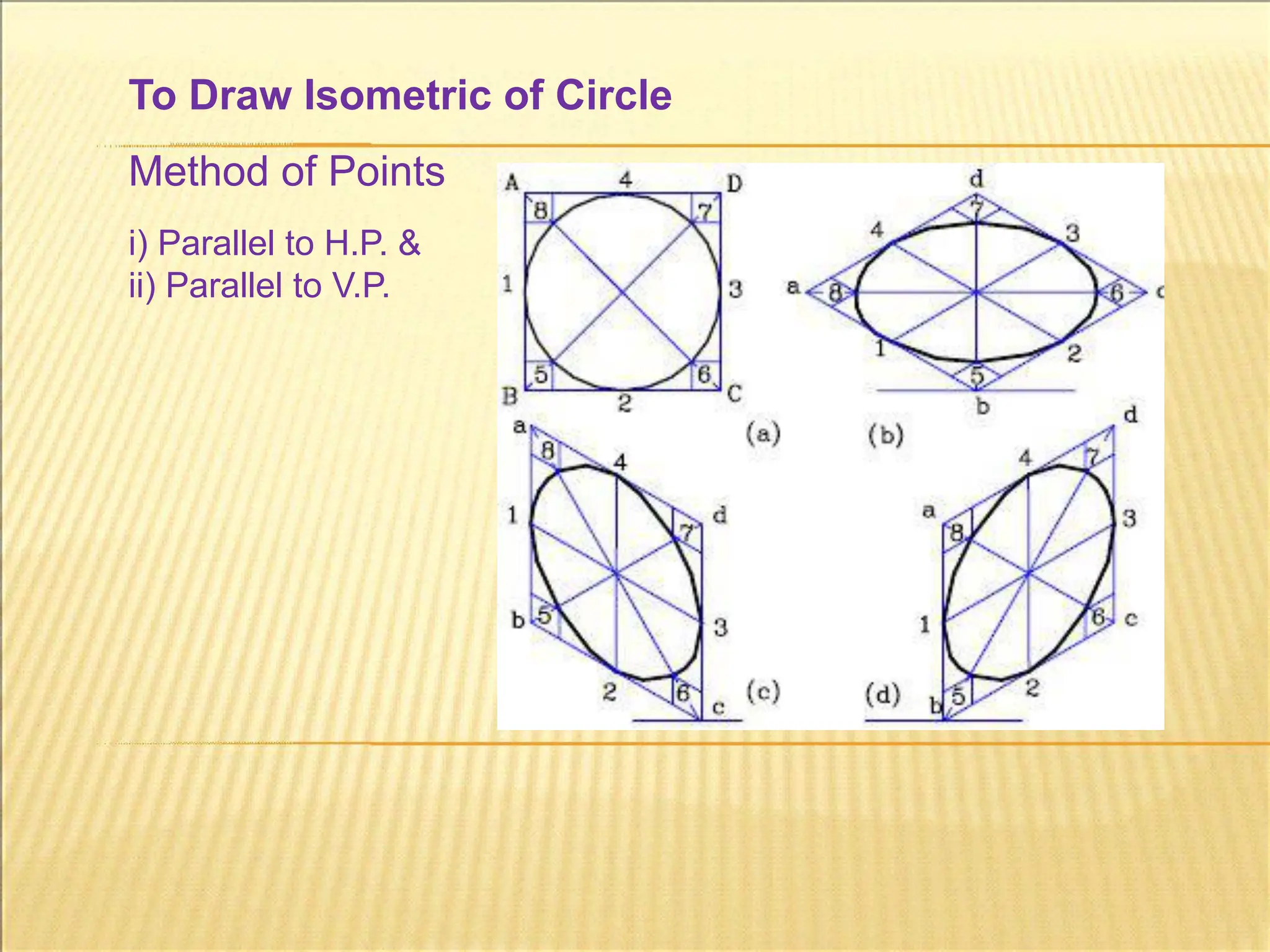
Iso. Projection: All lengths should be converted to Iso.
Length i.e. 9/11*True Length, except the radius of the
sphere.
109.
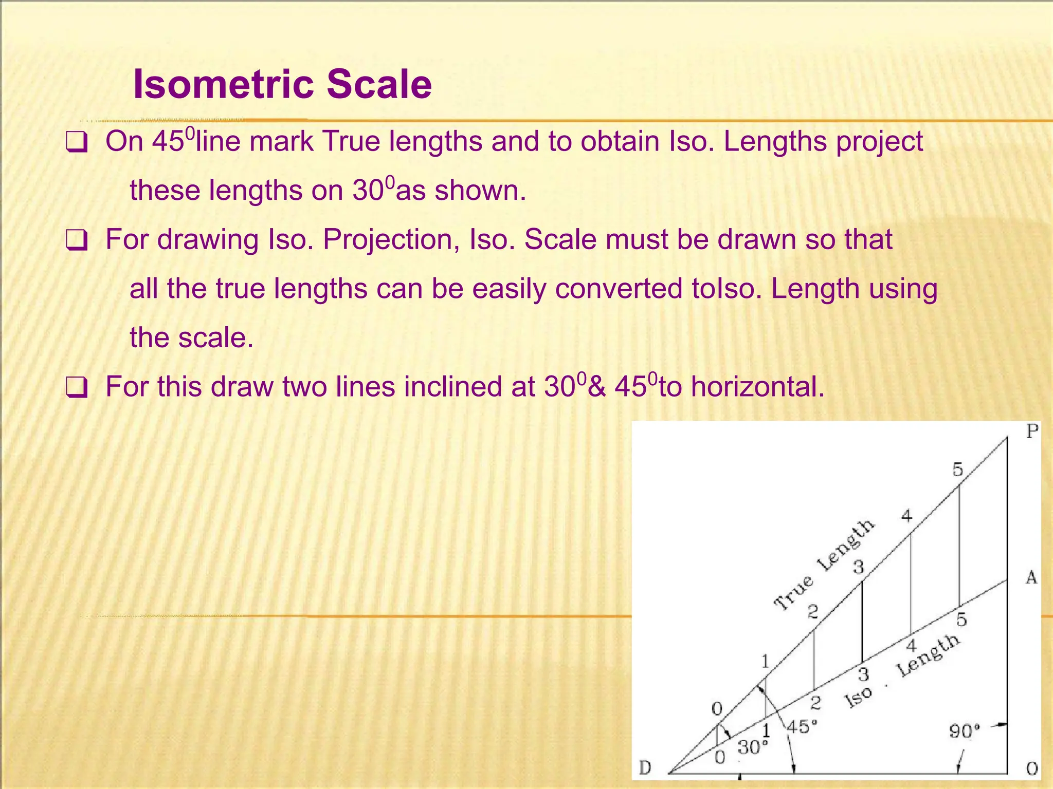
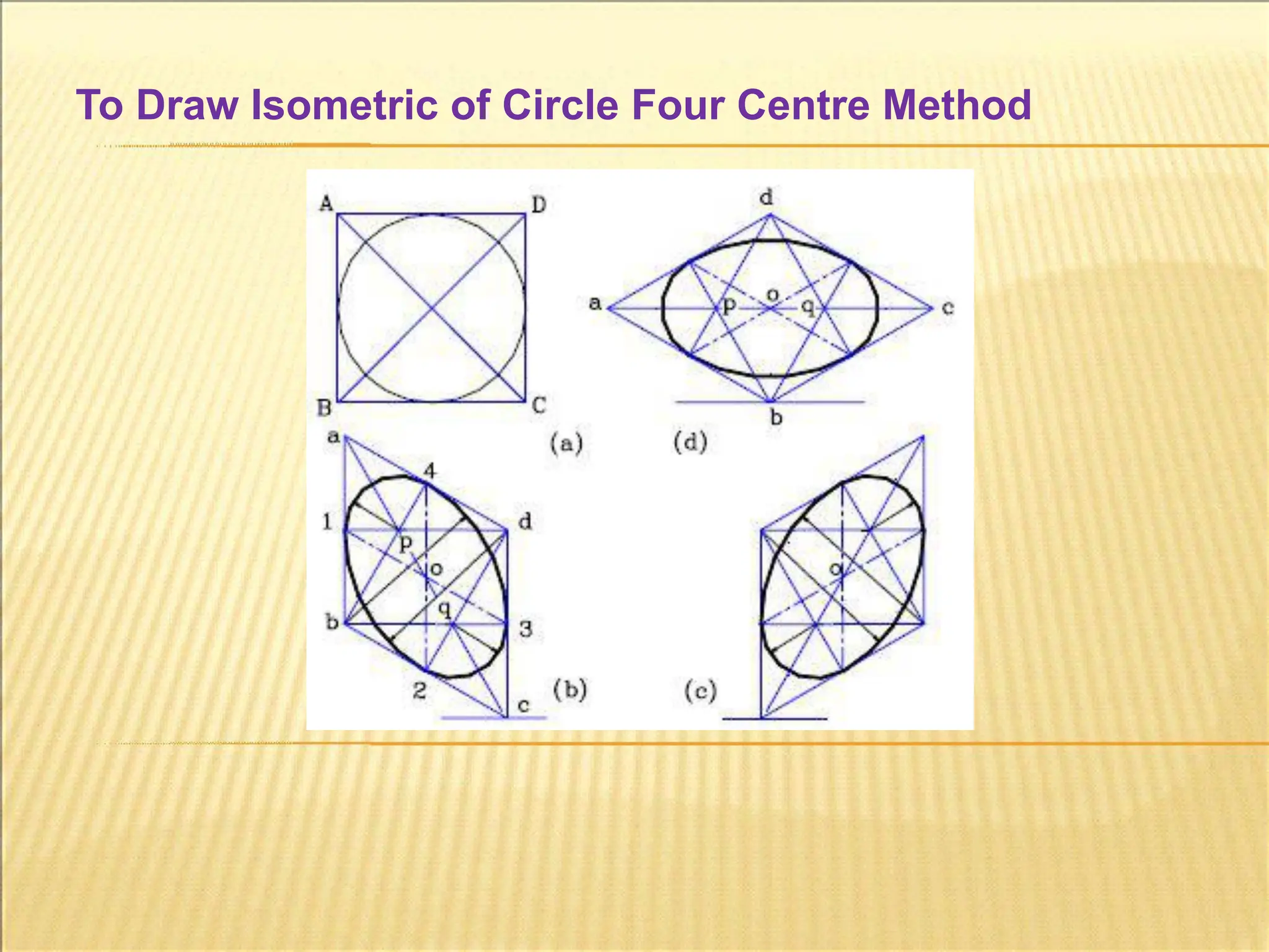
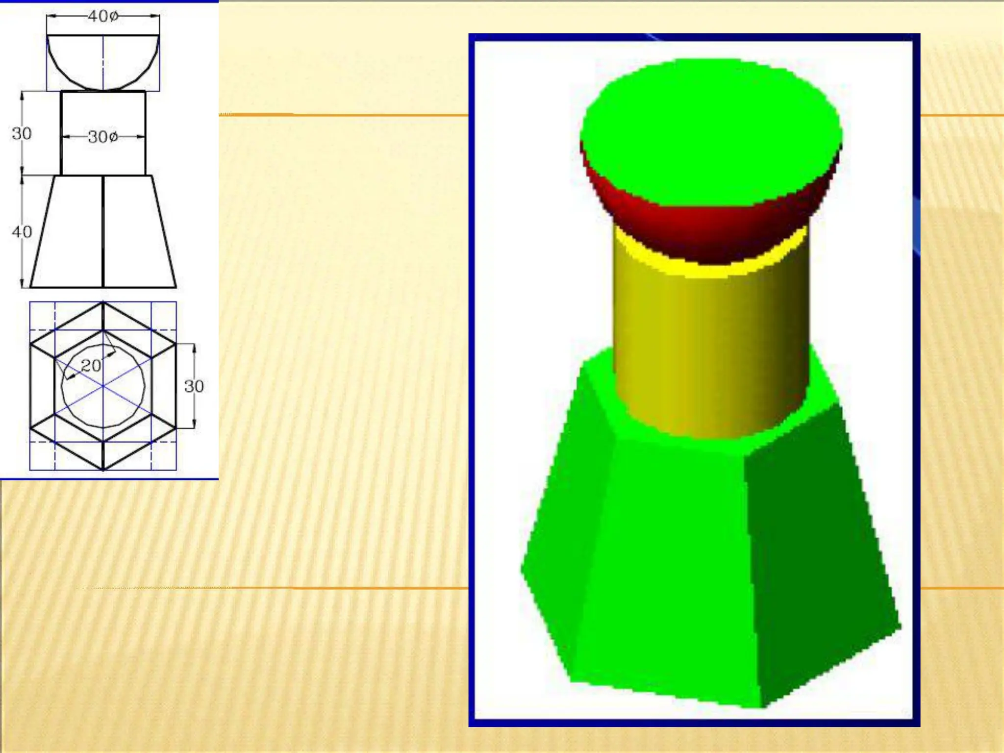
Isometric Scale
❑ On450
line mark True lengths and to obtain Iso. Lengths project
these lengths on 300
as shown.
❑ For drawing Iso. Projection, Iso. Scale must be drawn so that
all the true lengths can be easily converted toIso. Length using
the scale.
❑ For this draw two lines inclined at 300
& 450
to horizontal.
110.
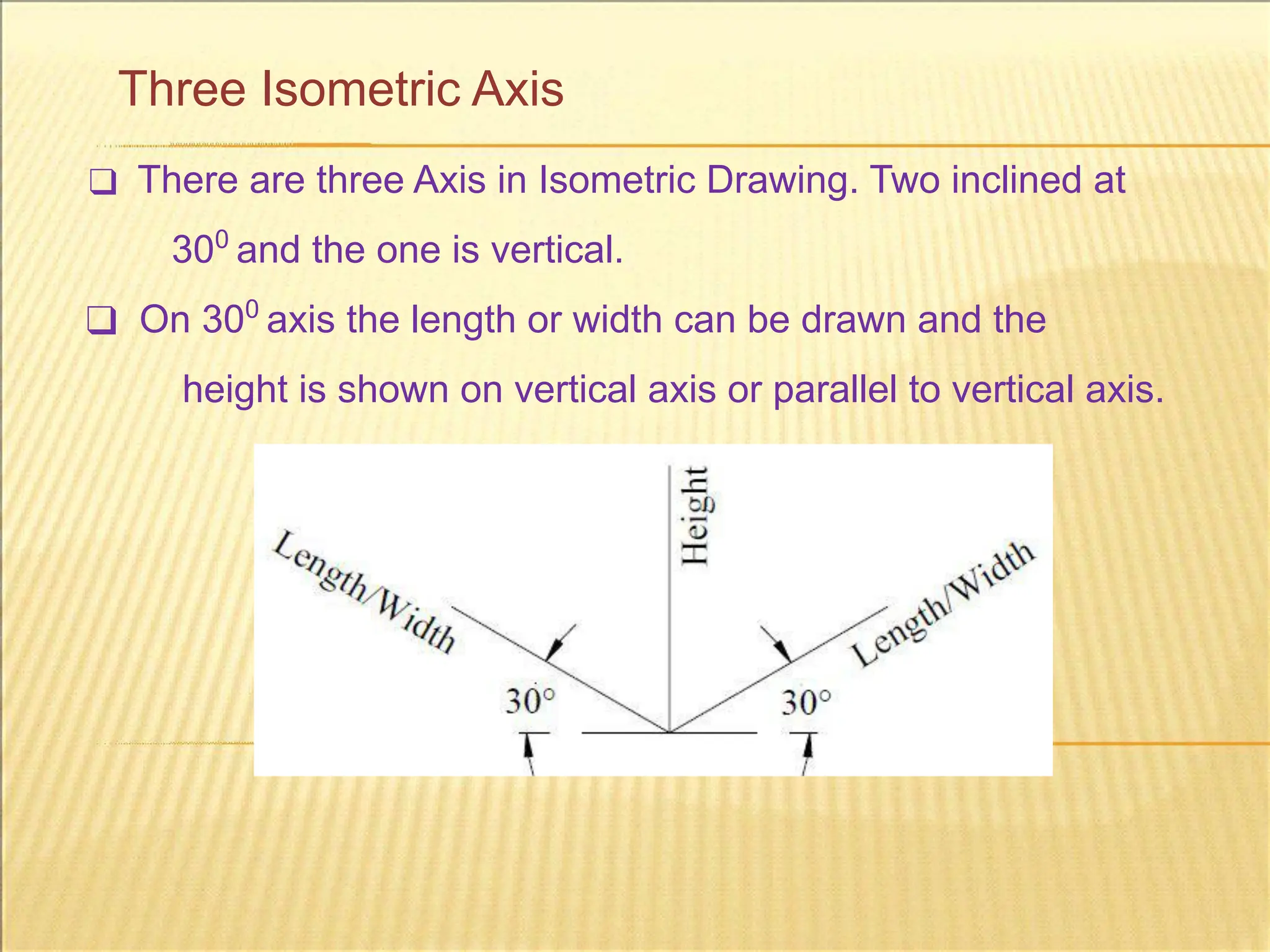
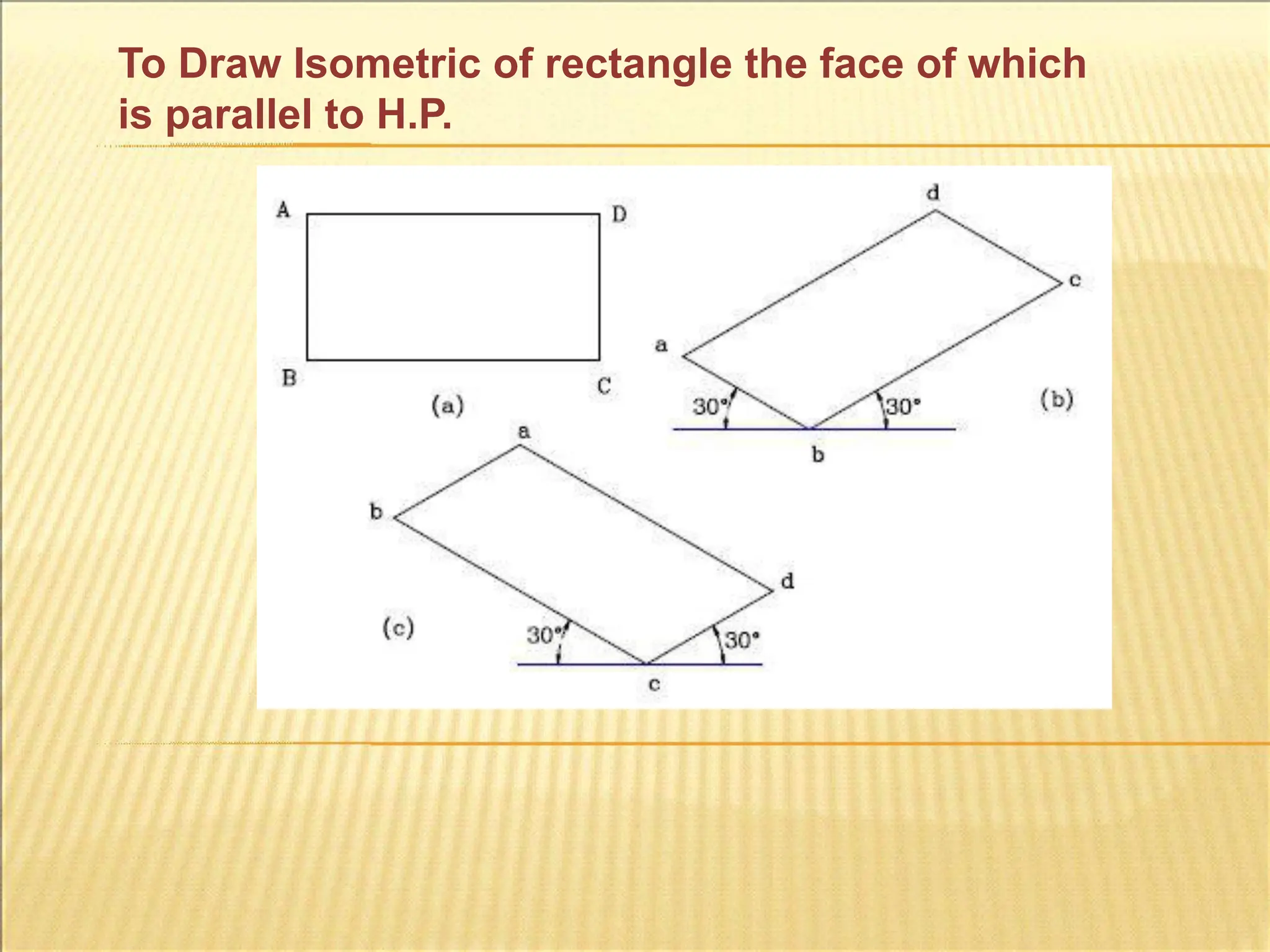
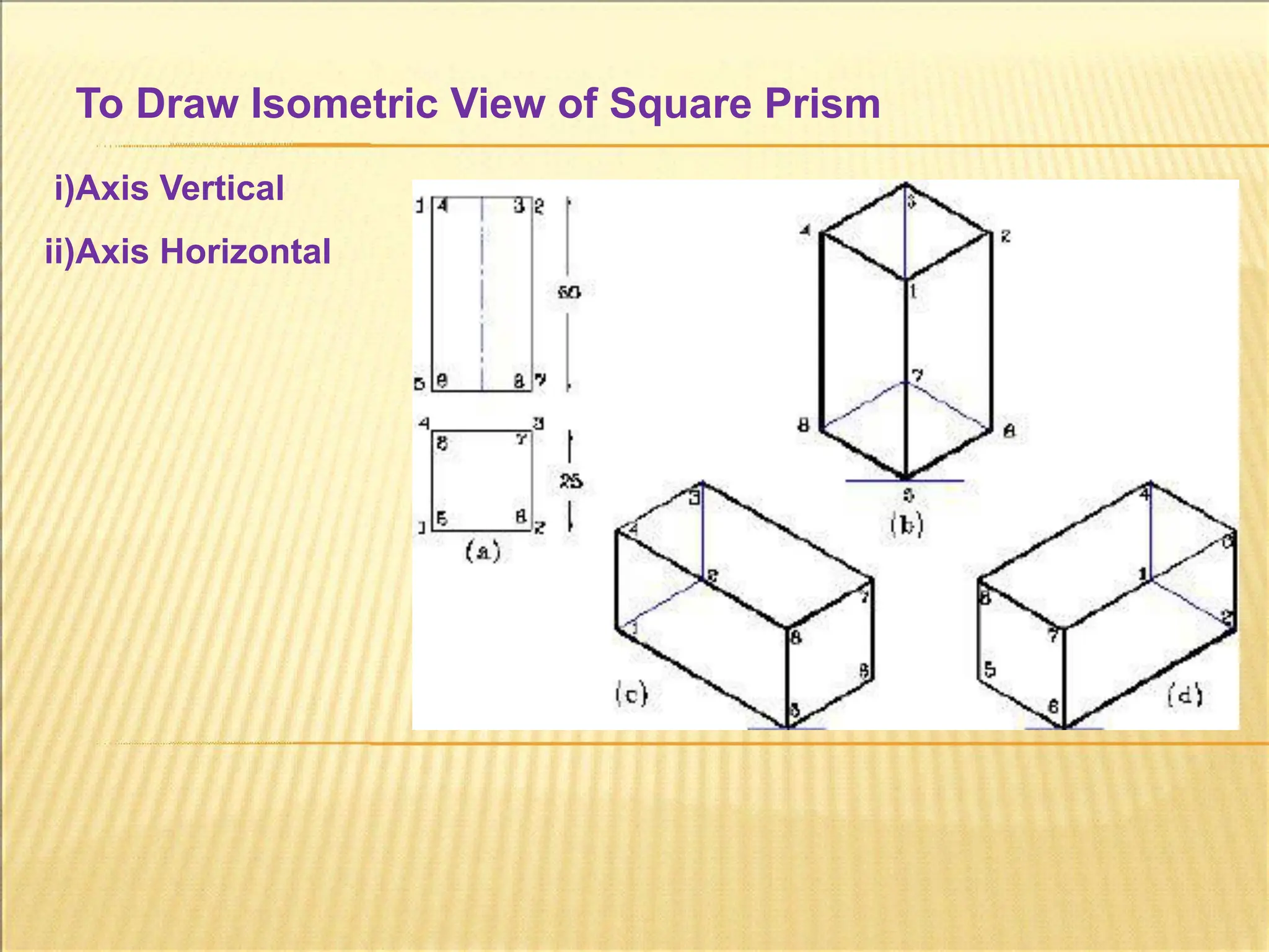
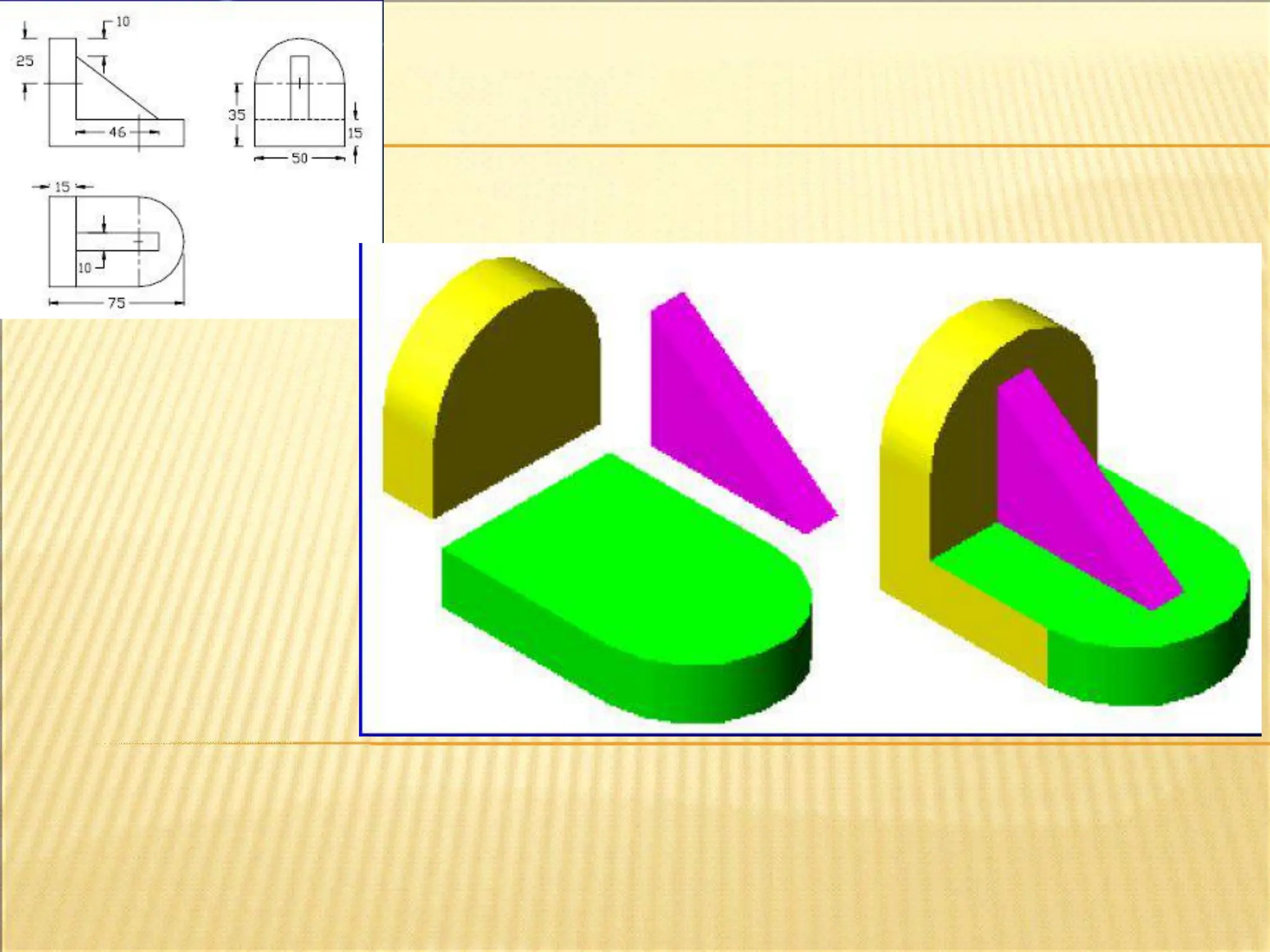
Three Isometric Axis
❑There are three Axis in Isometric Drawing. Two inclined at
300
and the one is vertical.
❑ On 300
axis the length or width can be drawn and the
height is shown on vertical axis or parallel to vertical axis.


![Excerciseeg(thedirectdata[1].com)](https://cdn.slidesharecdn.com/ss_thumbnails/excerciseegthedirectdata1-170802182329-thumbnail.jpg?width=640&height=640&fit=bounds)


