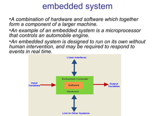
This document provides an overview of embedded systems and microcontrollers including the 8051 and 8086. It discusses key aspects of embedded systems such as they combine both hardware and software to perform a specific task. Examples are given of microcontrollers that control functions like engine control. The document then focuses on details of the 8051 microcontroller including its features, pins, and ports. It also provides details on the architecture and components of the 8086 microprocessor such as its execution unit, registers, bus interface unit, and segment registers.
To understand the basic concepts of 8085 microprocessor, microcontroller. The students will also learn about the programming methods and integration of peripherals to the micro-controller.
A microprocessor is an electronic component that is used by a computer to do its work. It is a central processing unit on a single integrated circuit chip containing millions of very small components including transistors, resistors, and diodes that work together. Some microprocessors in the 20th century required several chips. Microprocessors help to do everything from controlling elevators to searching the Web. Everything a computer does is described by instructions of computer programs, and microprocessors carry out these instructions many millions of times a second. [1]
Microprocessors were invented in the 1970s for use in embedded systems. The majority are still used that way, in such things as mobile phones, cars, military weapons, and home appliances. Some microprocessors are microcontrollers, so small and inexpensive that they are used to control very simple products like flashlights and greeting cards that play music when you open them. A few especially powerful microprocessors are used in personal computers.
A introduction to 8086 microprocessor
Your Crash course in your Pocket! Microprocessors: 8085, 8086, 80386, Pentium… Microcontrollers: 8051, ARM… Computer Organisation & Architecture
what is 8086 microprocessor, and its features
But we couldn’t pass up celebrating the 8086's anniversary in style. Time for a little DIY action to turn it into a work of art!
On this channel you can get education and knowledge for general issues and topics
SYBSC IT SEM IV EMBEDDED SYSTEMS UNIT III The 8051 MicrocontrollersArti Parab Academics
The 8051 Microcontrollers: Microcontrollers and Embedded processors, Overview of 8051 family. 8051 Microcontroller hardware, Input/output pins, Ports, and Circuits, External Memory. 8051 Programming in C: Data Types and time delay in 8051 C, I/O Programming, Logic operations, Data conversion Programs
Microcontrollers and Embedded Processors. Architecture – Block diagram of 8051, Pin configuration, Registers, Internal Memory, Timers, Port Structures, Interrupts. Assembly Language Programming - Addressing Modes, Instruction set of 8051, Simple programming examples in assembly language
This comprehensive program covers essential aspects of performance marketing, growth strategies, and tactics, such as search engine optimization (SEO), pay-per-click (PPC) advertising, content marketing, social media marketing, and more
Want to move your career forward? Looking to build your leadership skills while helping others learn, grow, and improve their skills? Seeking someone who can guide you in achieving these goals?
You can accomplish this through a mentoring partnership. Learn more about the PMISSC Mentoring Program, where you’ll discover the incredible benefits of becoming a mentor or mentee. This program is designed to foster professional growth, enhance skills, and build a strong network within the project management community. Whether you're looking to share your expertise or seeking guidance to advance your career, the PMI Mentoring Program offers valuable opportunities for personal and professional development.
Watch this to learn:
* Overview of the PMISSC Mentoring Program: Mission, vision, and objectives.
* Benefits for Volunteer Mentors: Professional development, networking, personal satisfaction, and recognition.
* Advantages for Mentees: Career advancement, skill development, networking, and confidence building.
* Program Structure and Expectations: Mentor-mentee matching process, program phases, and time commitment.
* Success Stories and Testimonials: Inspiring examples from past participants.
* How to Get Involved: Steps to participate and resources available for support throughout the program.
Learn how you can make a difference in the project management community and take the next step in your professional journey.
About Hector Del Castillo
Hector is VP of Professional Development at the PMI Silver Spring Chapter, and CEO of Bold PM. He's a mid-market growth product executive and changemaker. He works with mid-market product-driven software executives to solve their biggest growth problems. He scales product growth, optimizes ops and builds loyal customers. He has reduced customer churn 33%, and boosted sales 47% for clients. He makes a significant impact by building and launching world-changing AI-powered products. If you're looking for an engaging and inspiring speaker to spark creativity and innovation within your organization, set up an appointment to discuss your specific needs and identify a suitable topic to inspire your audience at your next corporate conference, symposium, executive summit, or planning retreat.
About PMI Silver Spring Chapter
We are a branch of the Project Management Institute. We offer a platform for project management professionals in Silver Spring, MD, and the DC/Baltimore metro area. Monthly meetings facilitate networking, knowledge sharing, and professional development. For event details, visit pmissc.org.
New Explore Careers and College Majors 2024.pdfDr. Mary Askew
Explore Careers and College Majors is a new online, interactive, self-guided career, major and college planning system.
The career system works on all devices!
For more Information, go to https://bit.ly/3SW5w8W
2. embedded system
•A combination of hardware and software which together
form a component of a larger machine.
•An example of an embedded system is a microprocessor
that controls an automobile engine.
•An embedded system is designed to run on its own without
human intervention, and may be required to respond to
events in real time.
3.
4.
5.
6. User interface
• Embedded systems range from no user
interface at all, in systems dedicated only to one
task, to complex graphical user interfaces that
resemble modern computer desktop operating
systems. Simple embedded devices
use buttons, LED, graphic or charcter LCD
7. Processors in embedded systems
• Embedded processors can be broken into two
broad categories. Ordinary microprocessors
(μP) use separate integrated circuits for memory
and peripherals. Microcontrollers (μC) have on-
chip peripherals, thus reducing power
consumption, size and cost. In contrast to the
personal computer market, many different
basic CPU architectures are used since software
is custom-developed for an application and is
not a commodity product installed by the end
user.
8. 8051 Microcontroller
The Intel 8051 microcontroller is one of the most
popular general purpose microcontrollers in use
today. The success of the Intel 8051 spawned a
number of clones, which are collectively referred
to as the MCS-51 family of microcontrollers
9. Some of the features that have made the
8051
• 4 KB on chip program memory.
• 128 bytes on chip data memory(RAM)
– 32 bytes devoted to register banks
– 16 bytes of bit-addressable memory
– 80 bytes of general-purpose memor
• 128 user defined software flags.
• 8-bit data bus
• 16-bit address bus
• 16 bit timers (usually 2, but may have more, or
less).
• 3 internal and 2 external interrupts
10.
11. • PIN 9: PIN 9 is the reset pin which is used to reset the
microcontroller’s internal registers and ports upon
starting up. (Pin should be held high for 2 machine
cycles.)
• PINS 18 & 19: The 8051 has a built-in oscillator
amplifier hence we need to only connect a crystal at
these pins to provide clock pulses to the circuit.
• PIN 40 and 20: Pins 40 and 20 are VCC and ground
respectively. The 8051 chip needs +5V 500mA to
function properly, although there are lower powered
versions like the Atmel 2051 which is a scaled down
version of the 8051 which runs on +3V
• PINS 29, 30 & 31: As described in the features of the
8051, this chip contains a built-in flash memory. In
order to program this we need to supply a voltage of
+12V at pin 31.
12. • Pin 29: If we uses an external ROM then it should
have a logic 0 which indicates Micro controller to read
data from memory.
• Pin 30: This Pin is used for ALE that is Address Latch
Enable. If we use multiple memory chips then this pin
is used to distinguish between them.It is activated
periodically with a constant rate of 1/6th of oscillator
frequency. This Pin also gives program pulse input
during programming of EPROM.
• Pin 31: If we have to use multiple memories then by
applying logic 1 to this pin instructs Micro controller to
read data from both memories first internal and
afterwards external.
13. • PORT P3 (Pins 10 to 17): PORT P3 acts as a normal
IO port, but Port P3 has additional functions such as,
serial transmit and receive pins, 2 external interrupt
pins, 2 external counter inputs, read and write pins for
memory access.
• PORT P2 (pins 21 to 28): PORT P2 can also be used
as a general purpose 8 bit port when no external
memory is present, but if external memory access is
required then PORT P2 will act as an address bus in
conjunction with PORT P0 to access external memory.
PORT P2 acts as A8-A15, as can be seen from fig 1.1
• PORT P0 (pins 32 to 39) PORT P0 can be used as a
general purpose 8 bit port when no external memory is
present, but if external memory acces
14. Microprocessor - 8086
• 8086 Microprocessor is an enhanced version of
8085Microprocessor that was designed by Intel
in 1976. It is a 16-bit Microprocessor having 20
address lines and16 data lines that provides up
to 1MB storage. It consists of powerful
instruction set, which provides operations like
multiplication and division easily.
• It supports two modes of operation, i.e.
Maximum mode and Minimum mode. Maximum
mode is suitable for system having multiple
processors and Minimum mode is suitable for
system having a single processor.
17. • Execution unit gives instructions to BIU stating from
where to fetch the data and then decode and
execute those instructions. Its function is to control
operations on data using the instruction decoder &
ALU. EU has no direct connection with system
EU (Execution Unit)
ALU
It handles all arithmetic and logical operations, like
+, −, ×, /, OR, AND, NOT operations.
Flag Register
It is a 16-bit register that behaves like a flip-flop,
i.e. it changes its status according to the result
stored in the accumulator. It has 9 flags and they
are divided into 2 groups − Conditional Flags and
18. Conditional Flags
It represents the result of the last arithmetic or logical
instruction executed. Following is the list of conditional flags
−
Carry flag − This flag indicates an overflow condition for
arithmetic operations.
Auxiliary flag − When an operation is performed at ALU, it
results in a carry/barrow from lower nibble (i.e. D0 – D3) to
upper nibble (i.e. D4 – D7), then this flag is set, i.e. carry
given by D3 bit to D4 is AF flag. The processor uses this flag
to perform binary to BCD conversion.
Parity flag − This flag is used to indicate the parity of the
result, i.e. when the lower order 8-bits of the result contains
even number of 1’s, then the Parity Flag is set. For odd
number of 1’s, the Parity Flag is reset.
Zero flag − This flag is set to 1 when the result of arithmetic
or logical operation is zero else it is set to 0.
19. • Sign flag − This flag holds the sign of the result, i.e.
when the result of the operation is negative, then the
sign flag is set to 1 else set to 0.
• Overflow flag − This flag represents the result when
the system capacity is exceeded.
20. • Control Flags
• Control flags controls the operations of the execution
unit. Following is the list of control flags −
• Trap flag − It is used for single step control and allows
the user to execute one instruction at a time for
debugging. If it is set, then the program can be run in
a single step mode
• Interrupt flag − It is an interrupt enable/disable flag, i.e.
used to allow/prohibit the interruption of a program. It
is set to 1 for interrupt enabled condition and set to 0
for interrupt disabled condition.
• Direction flag − It is used in string operation. As the
name suggests when it is set then string bytes are
accessed from the higher memory address to the
lower memory address and vice-a-versa.
21. • General purpose register
• There are 8 general purpose registers, i.e., AH, AL,
BH, BL, CH, CL, DH, and DL. These registers can be
used individually to store 8-bit data and can be used in
pairs to store 16bit data.
• AX register − It is also known as accumulator register.
It is used to store operands for arithmetic operations.
• BX register − It is used as a base register. It is used to
store the starting base address of the memory area
within the data segment.
• CX register − It is referred to as counter. It is used in
loop instruction to store the loop counter.
• DX register − This register is used to hold I/O port
address for I/O instruction
22. • BIU (Bus Interface Unit)
• BIU takes care of all data and addresses transfers on
the buses for the EU like sending addresses, fetching
instructions from the memory, reading data from the
ports and the memory as well as writing data to the
ports and the memory. EU has no direction connection
with System Buses so this is possible with the BIU. EU
and BIU are connected with the Internal Bus
• Instruction queue − BIU contains the instruction
queue. BIU gets upto 6 bytes of next instructions and
stores them in the instruction queue. When EU
executes instructions and is ready for its next
instruction, then it simply reads the instruction from
this instruction queue resulting in increased execution
speed.
23. • Segment register − BIU has 4 segment buses, i.e.
CS, DS, SS& ES. It holds the addresses of
instructions and data in memory, which are used by
the processor to access memory locations. It also
contains 1 pointer register IP, which holds the address
of the next instruction to executed by the EU.
• Instruction pointer − It is a 16-bit register used to
hold the address of the next instruction to be executed