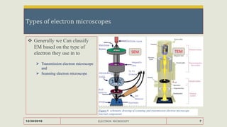
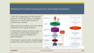
ELECTRON MICROSCOPY
Prepared by: Yohannes Reda
ID: CHS/PR159681/11
Mekelle university
college of health sciences
school of pharmacy
Presentation outline
 Objective
 Introduction
 Types of electron microscope
 TEM (working principle, instrumentation, limitation and application)
 SEM (working principle, instrumentation, limitation and application)
12/30/2018 ELECTRON MICROSCOPY 2
Objective
At the end of this presentation its expected
 To differentiate electron microscopy from light microscopy
 To grasp the working principle of TEM and SEM
 To list some of the instruments of both TEM and SEM
 The list pharmaceutical applications of SEM and TEM
12/30/2018 ELECTRON MICROSCOPY 3
Introduction to electron microscopy
 Electron microscope is a type of microscope that use beam of electrons to
magnify and see in detail up to Nano meter level.
 They can see features as small as tenth of a nanometer, such as individual atoms.
 These instruments are capable of atomic scale resolution
12/30/2018 ELECTRON MICROSCOPY 4
The resolution limit
12/30/2018 ELECTRON MICROSCOPY 5
Figure 1. the resolution limit of different imaging techniques along with
radiation and the size of biological objects
Why electrons ?
 An atom is made up of three kinds of particles – protons, neutrons, and electrons.
 The electrons, which are about 1800 times lighter than the nuclear particles,
occupy distinct orbits, each of which can accommodate a fixed maximum
number of electrons.
 When electrons are liberated from the atom-they behave like light.
12/30/2018 ELECTRON MICROSCOPY 6
Types of electron microscopes
 Generally we Can classify
EM based on the type of
electron they use in to
 Transmission electron microscope
and
 Scanning electron microscope
12/30/2018 ELECTRON MICROSCOPY 7
SEM TEM
Figure 6: schematic drawing of scanning and transmission electron microscope
internal components
Interaction between electrons and matter
12/30/2018 ELECTRON MICROSCOPY 8
Elastic interaction : No energy is transferred from the electron to the sample
Inelastic interaction :Energy is transferred from the primary electron to the specimen
Emission of electrons and radiation
Transmission electron microscopy (TEM)
 TEM is the direct counterpart of Light
microscope
 Involves passage of high velocity
electron beam through specimen, thin
enough to transmit 50% of the electrons
 Transmitted electrons – focused by lens
systems to form a 2 dimensional
magnified image (2D)
12/30/2018 ELECTRON MICROSCOPY 9
Figure : schematic drawing of transmission electron
microscope internal components
Instrumentation
 It is convenient to divide the instrument into three/four sections
 Illumination system
 Electron gun
 Condenser
 Specimen system
 Imaging system
 Vacuum system
12/30/2018 ELECTRON MICROSCOPY 10
Illumination system
Electron gun
 The electron source consists of a cathode and
an anode.
 The cathode is a tungsten filament/LaB6
which emits electrons when being heated.
 A negative cap confines the electrons into a
loosely focused beam.
 The beam is then accelerated towards the
specimen by the positive anode
Condenser
 The system allows electrons within a small
energy range to pass through, so the electrons
in the electron beam will have a well-defined
energy
 It’s a lens that help to focus the wide beams
of electrons to the specimen
 Unlike in the light microscope that uses glass
lenses the TEM uses magnetic (electro
magnetic) lenses
12/30/2018 ELECTRON MICROSCOPY 11
Vacuum system
 The electron beam must be generated in and traverse through the microscope
column under a high vacuum condition.
 The presence of air molecules will result in the collision and scattering of the
electrons from their path.
 In the electron microscope the vacuum is maintained by a series of highly
efficient vacuum pumps.
12/30/2018 ELECTRON MICROSCOPY 12
Imaging system
 The imaging system consists of another electromagnetic lens system and a
screen.
 The electromagnetic lens - two lens, one for refocusing the electrons after they
pass through the specimen, and the other for enlarging the image and projecting
it onto the screen.
 The screen has a phosphorescent plate which glows when being hit by electrons.
12/30/2018 ELECTRON MICROSCOPY 13
Imagining formation
 The basis of image formation in the TEM is the scattering of electrons.
 The scattering results in a shadow on the viewing screen or photographic film.
 Material with high atomic numbers will cause more scattering and produce a
deep shadow.
 Such material is termed "electron dense" and has high image contrast
12/30/2018 ELECTRON MICROSCOPY 14
Pharmaceutical applications of TEM
TEM can be used to analyze the internal structures of a given sample such as
 particle size, morphology, elemental composition, and crystallographic properties
 polymorph identification, mapping of crystal habit to crystal structure and crystal defect
characterization.
 Reveal changes in micro particle morphology induced by drug loading
Figure 5: micro particles before (c) and after drug loading (d)
12/30/2018 ELECTRON MICROSCOPY 15
Limitations
 Sampling is difficult and very costly
 Interpreting images- 2D images need a special skill to be interpreted
 Electron beam damage and safety-particularly polymers (and most organics) or
certain minerals and ceramics.
 Specimen preparation - the specimens have to be thin if you are going to get any
information using transmitted electrons in the TEM.
12/30/2018 ELECTRON MICROSCOPY 16
Scanning electron microscope(SEM)
 SEM uses a focused beam of high-energy electrons to generate a variety of
signals at the surface of solid specimens.
 Signals that derive from electron-sample interactions reveal information
including:
 Morphology, chemical composition, crystalline structure and orientation
of materials making up the sample.
12/30/2018 ELECTRON MICROSCOPY 17
Cont…
The typical scanning electron microscope laboratory
contains a machine with 2 components:
 the microscope column, including the electron gun
at the top, the column, down which the electron
beam travels, and the sample chamber at the base.
 the computer that drives the microscope, with the
additional bench controls
12/30/2018 ELECTRON MICROSCOPY 18
Figure 6: schematic drawing of scanning electron
microscope internal components
Interaction between matter and electrons
12/30/2018 ELECTRON MICROSCOPY 19
Working Principle(Scanning process and image formation)
-After the impingement of the primary
electrons on the specimens, secondary
electrons as well as other forms of
radiation are emitted.
-But only the secondary electrons will be
collected by the signal detector.
-In the detector these electrons strike a
scintillator and the light produced is
converted to electric signals by a
photomultiplier.
-The electric signal is then amplified and
displayed on the cathode ray tube (CRT).
12/30/2018 ELECTRON MICROSCOPY 20
Figure 6: schematic drawing of scanning electron microscope internal
components
Cont…
 In the SEM the electron beam is rapidly scanned back and forth in an orderly
pattern across the specimen surface.
 It is a composite of many individual image spots similar to the image formed on
the TV screen.
 The SEM has a specimen stage that allows the specimen to move freely so that
the surface of the specimen can be viewed from all angles.
12/30/2018 ELECTRON MICROSCOPY 21
Limitation
 The main disadvantage of SEM is that data are collected one pixel after the
other, which leads to a longer exposure time to the electron beam when
compared to TEM
 Samples must be solid
 samples must be stable in a vacuum approximately 10-5 - 10-6 torr (samples that
tend to outgas at low pressure are not compatible with this instrument)
12/30/2018 ELECTRON MICROSCOPY 22
Pharmaceutical application of SEM
 powder imaging and analysis, to gain insights into cellular interactions with new drugs,
and for applications in the most complicated cancer treatments.
 Within the field of industrial application and research, there is an increasing focus on
quality control at microscopic level, achieving high imagery level.
 Some of the uses are
 particle size distribution analysis,
 aspect ratio analysis,
 bioavailability studies and stability
12/30/2018 ELECTRON MICROSCOPY 23
TEM vs SEM
TEM SEM
6 lenses – C1, C2, objective, 3
projector
3 lenses – 2 condensor, 1
objective
High accelerating voltage -
penetration
low accelerating voltage
Not complicated Specimen Stage – complicated
X & y axis X,Y,Z-axis, tilting, rotating
12/30/2018 ELECTRON MICROSCOPY 24
Table 1: TEM vs SEM
Summary
 EM are useful tools for looking a range of samples.
 EM based analysis combined with other analysis techniques can assist
 Complete characterization of samples.
 They remain a very powerful analysis tool in the manufacturing of
pharmaceuticals.
12/30/2018 ELECTRON MICROSCOPY 25
References
 Amelinckx, S., Van Dyck, D., van Landuyt, J. and Van Tendeloo, G. eds., 2008. Handbook of
Microscopy: Applications in Materials Science, Solid-State Physics, and Chemistry, Methods
II. John Wiley & Sons.
 Carlton, R.A., 2011. Scanning electron microscopy and energy-dispersive X-ray spectrometry.
In Pharmaceutical Microscopy (pp. 85-130). Springer, New York, NY.
 Colliex, C., 2014. Seeing and measuring with electrons: Transmission electron microscopy
today and tomorrow–An introduction. Comptes Rendus Physique, 15(2-3), pp.101-109.
 Eddleston, M.D., Bithell, E.G. and Jones, W., 2010. Transmission electron microscopy of
pharmaceutical materials. Journal of pharmaceutical sciences, 99(9), pp.4072-4083.
 Egerton, R.F., 2005. Physical principles of electron microscopy (p. 41). New York: Springer.
 Fultz, B. and Howe, J.M., 2012. Transmission electron microscopy and diffractometry of
materials. Springer Science & Business Media.
12/30/2018 ELECTRON MICROSCOPY 26
27

Electron microscopy

  • 1.
    ELECTRON MICROSCOPY Prepared by:Yohannes Reda ID: CHS/PR159681/11 Mekelle university college of health sciences school of pharmacy
  • 2.
    Presentation outline  Objective Introduction  Types of electron microscope  TEM (working principle, instrumentation, limitation and application)  SEM (working principle, instrumentation, limitation and application) 12/30/2018 ELECTRON MICROSCOPY 2
  • 3.
    Objective At the endof this presentation its expected  To differentiate electron microscopy from light microscopy  To grasp the working principle of TEM and SEM  To list some of the instruments of both TEM and SEM  The list pharmaceutical applications of SEM and TEM 12/30/2018 ELECTRON MICROSCOPY 3
  • 4.
    Introduction to electronmicroscopy  Electron microscope is a type of microscope that use beam of electrons to magnify and see in detail up to Nano meter level.  They can see features as small as tenth of a nanometer, such as individual atoms.  These instruments are capable of atomic scale resolution 12/30/2018 ELECTRON MICROSCOPY 4
  • 5.
    The resolution limit 12/30/2018ELECTRON MICROSCOPY 5 Figure 1. the resolution limit of different imaging techniques along with radiation and the size of biological objects
  • 6.
    Why electrons ? An atom is made up of three kinds of particles – protons, neutrons, and electrons.  The electrons, which are about 1800 times lighter than the nuclear particles, occupy distinct orbits, each of which can accommodate a fixed maximum number of electrons.  When electrons are liberated from the atom-they behave like light. 12/30/2018 ELECTRON MICROSCOPY 6
  • 7.
    Types of electronmicroscopes  Generally we Can classify EM based on the type of electron they use in to  Transmission electron microscope and  Scanning electron microscope 12/30/2018 ELECTRON MICROSCOPY 7 SEM TEM Figure 6: schematic drawing of scanning and transmission electron microscope internal components
  • 8.
    Interaction between electronsand matter 12/30/2018 ELECTRON MICROSCOPY 8 Elastic interaction : No energy is transferred from the electron to the sample Inelastic interaction :Energy is transferred from the primary electron to the specimen Emission of electrons and radiation
  • 9.
    Transmission electron microscopy(TEM)  TEM is the direct counterpart of Light microscope  Involves passage of high velocity electron beam through specimen, thin enough to transmit 50% of the electrons  Transmitted electrons – focused by lens systems to form a 2 dimensional magnified image (2D) 12/30/2018 ELECTRON MICROSCOPY 9 Figure : schematic drawing of transmission electron microscope internal components
  • 10.
    Instrumentation  It isconvenient to divide the instrument into three/four sections  Illumination system  Electron gun  Condenser  Specimen system  Imaging system  Vacuum system 12/30/2018 ELECTRON MICROSCOPY 10
  • 11.
    Illumination system Electron gun The electron source consists of a cathode and an anode.  The cathode is a tungsten filament/LaB6 which emits electrons when being heated.  A negative cap confines the electrons into a loosely focused beam.  The beam is then accelerated towards the specimen by the positive anode Condenser  The system allows electrons within a small energy range to pass through, so the electrons in the electron beam will have a well-defined energy  It’s a lens that help to focus the wide beams of electrons to the specimen  Unlike in the light microscope that uses glass lenses the TEM uses magnetic (electro magnetic) lenses 12/30/2018 ELECTRON MICROSCOPY 11
  • 12.
    Vacuum system  Theelectron beam must be generated in and traverse through the microscope column under a high vacuum condition.  The presence of air molecules will result in the collision and scattering of the electrons from their path.  In the electron microscope the vacuum is maintained by a series of highly efficient vacuum pumps. 12/30/2018 ELECTRON MICROSCOPY 12
  • 13.
    Imaging system  Theimaging system consists of another electromagnetic lens system and a screen.  The electromagnetic lens - two lens, one for refocusing the electrons after they pass through the specimen, and the other for enlarging the image and projecting it onto the screen.  The screen has a phosphorescent plate which glows when being hit by electrons. 12/30/2018 ELECTRON MICROSCOPY 13
  • 14.
    Imagining formation  Thebasis of image formation in the TEM is the scattering of electrons.  The scattering results in a shadow on the viewing screen or photographic film.  Material with high atomic numbers will cause more scattering and produce a deep shadow.  Such material is termed "electron dense" and has high image contrast 12/30/2018 ELECTRON MICROSCOPY 14
  • 15.
    Pharmaceutical applications ofTEM TEM can be used to analyze the internal structures of a given sample such as  particle size, morphology, elemental composition, and crystallographic properties  polymorph identification, mapping of crystal habit to crystal structure and crystal defect characterization.  Reveal changes in micro particle morphology induced by drug loading Figure 5: micro particles before (c) and after drug loading (d) 12/30/2018 ELECTRON MICROSCOPY 15
  • 16.
    Limitations  Sampling isdifficult and very costly  Interpreting images- 2D images need a special skill to be interpreted  Electron beam damage and safety-particularly polymers (and most organics) or certain minerals and ceramics.  Specimen preparation - the specimens have to be thin if you are going to get any information using transmitted electrons in the TEM. 12/30/2018 ELECTRON MICROSCOPY 16
  • 17.
    Scanning electron microscope(SEM) SEM uses a focused beam of high-energy electrons to generate a variety of signals at the surface of solid specimens.  Signals that derive from electron-sample interactions reveal information including:  Morphology, chemical composition, crystalline structure and orientation of materials making up the sample. 12/30/2018 ELECTRON MICROSCOPY 17
  • 18.
    Cont… The typical scanningelectron microscope laboratory contains a machine with 2 components:  the microscope column, including the electron gun at the top, the column, down which the electron beam travels, and the sample chamber at the base.  the computer that drives the microscope, with the additional bench controls 12/30/2018 ELECTRON MICROSCOPY 18 Figure 6: schematic drawing of scanning electron microscope internal components
  • 19.
    Interaction between matterand electrons 12/30/2018 ELECTRON MICROSCOPY 19
  • 20.
    Working Principle(Scanning processand image formation) -After the impingement of the primary electrons on the specimens, secondary electrons as well as other forms of radiation are emitted. -But only the secondary electrons will be collected by the signal detector. -In the detector these electrons strike a scintillator and the light produced is converted to electric signals by a photomultiplier. -The electric signal is then amplified and displayed on the cathode ray tube (CRT). 12/30/2018 ELECTRON MICROSCOPY 20 Figure 6: schematic drawing of scanning electron microscope internal components
  • 21.
    Cont…  In theSEM the electron beam is rapidly scanned back and forth in an orderly pattern across the specimen surface.  It is a composite of many individual image spots similar to the image formed on the TV screen.  The SEM has a specimen stage that allows the specimen to move freely so that the surface of the specimen can be viewed from all angles. 12/30/2018 ELECTRON MICROSCOPY 21
  • 22.
    Limitation  The maindisadvantage of SEM is that data are collected one pixel after the other, which leads to a longer exposure time to the electron beam when compared to TEM  Samples must be solid  samples must be stable in a vacuum approximately 10-5 - 10-6 torr (samples that tend to outgas at low pressure are not compatible with this instrument) 12/30/2018 ELECTRON MICROSCOPY 22
  • 23.
    Pharmaceutical application ofSEM  powder imaging and analysis, to gain insights into cellular interactions with new drugs, and for applications in the most complicated cancer treatments.  Within the field of industrial application and research, there is an increasing focus on quality control at microscopic level, achieving high imagery level.  Some of the uses are  particle size distribution analysis,  aspect ratio analysis,  bioavailability studies and stability 12/30/2018 ELECTRON MICROSCOPY 23
  • 24.
    TEM vs SEM TEMSEM 6 lenses – C1, C2, objective, 3 projector 3 lenses – 2 condensor, 1 objective High accelerating voltage - penetration low accelerating voltage Not complicated Specimen Stage – complicated X & y axis X,Y,Z-axis, tilting, rotating 12/30/2018 ELECTRON MICROSCOPY 24 Table 1: TEM vs SEM
  • 25.
    Summary  EM areuseful tools for looking a range of samples.  EM based analysis combined with other analysis techniques can assist  Complete characterization of samples.  They remain a very powerful analysis tool in the manufacturing of pharmaceuticals. 12/30/2018 ELECTRON MICROSCOPY 25
  • 26.
    References  Amelinckx, S.,Van Dyck, D., van Landuyt, J. and Van Tendeloo, G. eds., 2008. Handbook of Microscopy: Applications in Materials Science, Solid-State Physics, and Chemistry, Methods II. John Wiley & Sons.  Carlton, R.A., 2011. Scanning electron microscopy and energy-dispersive X-ray spectrometry. In Pharmaceutical Microscopy (pp. 85-130). Springer, New York, NY.  Colliex, C., 2014. Seeing and measuring with electrons: Transmission electron microscopy today and tomorrow–An introduction. Comptes Rendus Physique, 15(2-3), pp.101-109.  Eddleston, M.D., Bithell, E.G. and Jones, W., 2010. Transmission electron microscopy of pharmaceutical materials. Journal of pharmaceutical sciences, 99(9), pp.4072-4083.  Egerton, R.F., 2005. Physical principles of electron microscopy (p. 41). New York: Springer.  Fultz, B. and Howe, J.M., 2012. Transmission electron microscopy and diffractometry of materials. Springer Science & Business Media. 12/30/2018 ELECTRON MICROSCOPY 26
  • 27.