This section discusses plane axisymmetric problems in solid mechanics. These are problems where both the geometry and loading exhibit rotational symmetry about an axis. Key points:
- Plane axisymmetric problems can be analyzed in two dimensions, with the stress and strain components independent of the circumferential coordinate.
- These problems can involve either plane stress or plane strain. Navier's equation governs displacements in both cases.
- The solutions provide expressions for stress and strain throughout the material in terms of constants determined by the boundary conditions.
- An example solves for the stresses in a thick-walled cylinder under internal pressure, showing how the maximum tangential stress occurs at the inner surface.
This document provides an overview of Chapter 2 from the textbook "Mechanics of Materials" which covers stress and strain under axial loading. The chapter discusses key topics like normal strain, stress-strain diagrams for ductile and brittle materials, Hooke's law, elastic vs plastic behavior, fatigue, thermal stresses, Poisson's ratio, generalized Hooke's law, dilatation and the bulk modulus, shearing strain, and relationships between elastic moduli. Sample problems are provided as examples for determining deformations under axial loading and for statically indeterminate structures.
This document discusses the analysis and design of concrete floor systems. It begins with an overview of basic design steps for slabs, including recalling design procedures for shear and flexure. It then classifies different types of concrete floor systems such as one-way slabs, two-way slabs, flat plates, and joist systems. The document provides examples of analyzing and designing a one-way slab using the ACI approximate method and discussing the effect of beam spacing on slab moments. It concludes with references for further information.
This document contains a summary of a refresher course covering various structural analysis problems. It includes 5 situations involving calculating reactions, tensions, stresses, and shear forces for different structures. The document tests understanding through multiple choice questions after explaining the concepts and showing the calculations for each situation. The situations involve analyzing forces on a portable seat, cables supporting a ceiling, stresses on an element using Mohr's circle, forces on a bridge girder under loading, and stresses in a hollow circular signage pole.
Structural Reliability Assessment of a Winch Drum for an Offshore CraneLes Moyo
The document summarizes literature on the structural reliability assessment of hoist drum flanges. It discusses that hoist drum failures are commonly due to flange failures caused by underestimating flange forces. While drum stresses are well-researched, flange forces are complex to determine. Early studies developed formulas to calculate flange pressures based on rope tension, layers, and geometry. However, flange design in standards is still lacking. The project assesses flange design methods, evaluates a case study where flanges failed twice, and calculates failure probabilities to evaluate reliability.
This document provides information on shell theory and the modeling of various shell structures. It begins by defining a shell as a thin-walled three-dimensional structure. It then discusses shell thickness and functions. The document also covers modeling shells using the static-geometric hypothesis of Kirchhoff-Love and thin shell theory. It provides the mathematical foundations of differential geometry as applied to shell surfaces. Finally, it gives examples of generating surfaces for different shell types like ellipsoids, hyperboloids, cones, paraboloids, cylinders, and applies meshing techniques.
22-Design of Four Bolt Extended Endplate Connection (Steel Structural Design ...Hossam Shafiq II
This document provides design assumptions and procedures for a four-bolt unstiffened extended end-plate moment connection. It includes steps to size bolts, determine the required end plate thickness, and design fillet welds. An example is provided to demonstrate the design of a connection between a W460x74 beam and W360x147 column using A36 steel. The example calculates bolt sizes, selects an end plate thickness of 20mm, and determines required fillet weld sizes.
The document discusses different stress and failure criteria used to analyze materials. It describes the Tresca, Von Mises, and Rankine criteria, which use maximum shear stress, equivalent deviatoric strain energy, and limits on principal stresses respectively to determine failure. The Von Mises criterion applies best to isotropic ductile metals, while Tresca and Rankine criteria can also be used for such materials. Rankine is more suitable for low-cohesion materials like ceramics. The appropriate criterion depends on the material properties.
This document provides information about the Strength of Materials CIE 102 course for first year B.E. degree students. It includes a list of 10 topics that will be covered in the course, such as simple stress and strain, shearing force and bending moment, and stability of columns. It also lists several reference books for the course and provides an overview of concepts that will be discussed in the first chapter, including stress, strain, stress-strain diagrams, and ductile vs brittle materials.
This document contains an application form for approval of sewerage works in accordance with the Sewerage Systems and Septic Tanks (Planning, Design and Construction) Regulations 1996. The form includes sections for applicant details, description of proposed works, landowner agreement to surrender sewerage land to the government, and engineer and qualified person declarations certifying design compliance. An additional page lists 15 required particulars to be submitted with each application, such as site plans, sewer designs, treatment plant details, population served, and effluent standards.
The document discusses the design and erection of column base plates. It covers types of base plates for different load cases including axial compression, tension, and combined axial and moment loads. Key topics covered include base plate and anchor rod materials, design for concrete crushing and bending, anchor rod design, and erection procedures. Diagrams illustrate critical sections and design equations for different limit states. Construction tolerances and OSHA standards for base plate design are also summarized.
The use of Calculus is very important in every aspects of engineering.
The use of Differential equation is very much applied in the concept of Elastic beams.
This document discusses the use of Airy stress functions to solve problems in two-dimensional elasticity. It provides the equations relating stresses to the Airy stress function in plane stress, plane strain, and polar coordinates. Examples are given to show how specific Airy stress functions can be used to solve problems like bending of beams, stresses in curved beams with end moments, and stresses in a quarter-circle beam under an end load.
This document discusses bending, shear and moment diagrams, and bending deformation of beams. It provides examples of constructing shear and moment diagrams for different types of beams under various loading conditions. The key relationships discussed are:
1) The relationship between load and shear is the change in shear equals the area under the load diagram.
2) The relationship between shear and bending moment is the change in moment equals the area under the shear diagram.
3) Bending of a beam leads to elongation of fibers on the outside of the bend and compression of fibers on the inside. The maximum strain occurs at the surface farthest from the neutral axis.
Design by Analysis - A general guideline for pressure vesselAnalyzeForSafety
This presentation file is provided by Mr. Ghanbari and published under permission.
The presentation gives an introduction and general guideline for pressure vessel design by analysis.
The “design by analysis” procedures are intended to guard against eight possible pressure vessel failure modes by performing a detailed stress analysis of the vessel with the sufficient design factors. The failure modes are:
1.excessive elastic deformation, including elastic instability,
2.excessive plastic deformation,
3.brittle fracture,
4.stress rupture/creep deformation (inelastic),
5.plastic instability - incremental collapse,
6.high strain - low cycle fatigue,
7.stress corrosion, and
8.corrosion fatigue
Most of the “design by analysis” procedures that are given in ASME BPVC relate to designs based on “elastic analysis.”
The design-by-analysis requirements are organized based on protection against the failure modes listed below. The component shall be evaluated for each applicable failure mode. If multiple assessment procedures are provided for a failure mode, only one of these procedures must be satisfied to qualify the design of a component.
a)All pressure vessels within the scope of this Division, irrespective of size or pressure, shall be provided with protection against overpressure in accordance with the requirements of this Part.
b)Protection Against Plastic Collapse – these requirements apply to all components where the thickness and configuration of the component is established using design-by-analysis rules.
c)Protection Against Local Failure – these requirements apply to all components where the thickness and configuration of the component is established using design-by-analysis rules. It is not necessary to evaluate the local strain limit criterion if the component design is in accordance with Part 4 (i.e. component wall thickness and weld detail per paragraph 4.2).
d)Protection Against Collapse From Buckling – these requirements apply to all components where the thickness and configuration of the component is established using design-by-analysis rules and the applied loads result in a compressive stress field.
e)Protection Against Failure From Cyclic Loading – these requirements apply to all components where the thickness and configuration of the component is established using design-by-analysis rules and the applied loads are cyclic. In addition, these requirements can also be used to qualify a component for cyclic loading where the thickness and size of the component are established using the design-by-rule requirements of Part 4.
Chapter 6: Pure Bending and Bending with Axial ForcesMonark Sutariya
This summary provides the key points about pure bending and bending with axial forces from the document:
1. Pure bending occurs when a beam segment is in equilibrium under bending moments alone, with examples being a cantilever loaded at the end or a beam segment between concentrated forces.
2. For beams with symmetric cross-sections, plane sections remain plane after bending according to the fundamental flexure theory. The elastic flexure formula gives the normal stress as proportional to the bending moment and the distance from the neutral axis.
3. The second moment of area, or moment of inertia, represents the beam's resistance to bending and is used to calculate maximum bending stresses. The elastic section modulus is a ratio of the moment
The document discusses concepts of stress, including:
1. Stress is defined as the force per unit area acting on a surface or section. There are two main types: normal stress and shear stress.
2. To determine if a structure can safely support a load, both the internal forces and the material properties must be considered.
3. Allowable stress values lower than the actual failure stress are used in design, with factors of safety typically between 1-3 depending on the application. This ensures the structure does not fail under expected loading conditions.
This document provides information about the design of strap footings. It begins with an overview of strap footings, noting they are used to connect an eccentrically loaded column footing to an interior column. The strap transmits moment caused by eccentricity to the interior footing to generate uniform soil pressure beneath both footings.
It then outlines the basic considerations for strap footing design: 1) the strap must be rigid, 2) footings should have equal soil pressures to avoid differential settlement, and 3) the strap should be out of contact with soil to avoid soil reactions. Finally, it provides the step-by-step process for designing a strap footing, including proportioning footing dimensions, evaluating soil pressures, designing reinforcement,
This document discusses modeling a hot compression test using finite element analysis in ABAQUS. It describes:
1) Creating parts for the deformable bulk material and rigid press and assembling them, defining materials, contacts, steps, and meshing.
2) Developing a viscoplastic constitutive model and implementing it in ABAQUS through user subroutines UMAT and VUMAT.
3) Running a simulation of hot plain strain compression of copper and comparing results from UMAT and VUMAT.
08-Strength of Welded Connections (Steel Structural Design & Prof. Shehab Mou...Hossam Shafiq II
The document discusses the strength of welded connections, including fillet and groove welds. It provides the equations to calculate the strength of fillet welds based on weld size and length. It also provides equations for calculating the strength of gusset plates based on yield strength, tensile strength, and area. An example calculation is shown for a welded connection with longitudinal and transverse welds. The strength is calculated for the welds, angles, and gusset plate. The governing strength is found to be the yielding of the gusset plate at 457.2 kN.
This lecture provides an introduction to finite element analysis (FEA). It discusses the basic concepts of FEA, including dividing a complex object into simple finite elements and using polynomial terms to describe field quantities within each element. The lecture covers the history and applications of FEA, as well as the basic procedure, which involves meshing a structure into elements, describing element behavior, assembling elements at nodes, solving the system of equations, and calculating results. It also reviews matrix algebra concepts needed for FEA. Finally, it presents the simple example of a spring element and spring system to demonstrate the finite element modeling process.
This document contains 15 problems related to determining stresses in beams undergoing bending and shearing. The problems involve calculating stresses in beams with various cross-sectional shapes under different loading conditions. The beams are made of materials like steel, wood, and brass. Parameters like moment of inertia, shear force, beam dimensions, and material properties are provided to calculate stresses.
This document contains 36 problems related to mechanics of solids dealing with topics like normal stress, shearing stress, axial deformation, shearing deformation, and statically indeterminate members. The problems involve calculating stresses, strains, loads, diameters, thicknesses, and other values using given structural properties and load/force information. Equations related to stress, strain, elasticity, and structural analysis are applied to solve the engineering problems.
Pirelli produces motorcycle tires for various applications including racing, sport, touring, custom, urban, enduro, motocross, scooter/moped, and tubes. For racing applications, Pirelli offers the Diablo Superbike, Diablo Supercorsa SC, Diablo Wet, and Diablo Rain tires. These tires are designed for use on track and provide high performance, control, and traction for professional and amateur racers. New sizes have been added for some models.
1) The document calculates wind loads on a photovoltaic system structure according to EN1991-4 standards.
2) It provides assumptions made, describes the structure dimensions, and determines basic wind values like velocity and pressure for the site.
3) It then calculates wind loads on different zones of the canopy roof for various wind directions, including net pressure coefficients and resulting wind forces on frame members. Several load cases are defined.
O documento fornece tabelas práticas para ajudar na escolha do diâmetro correto do pino de dobramento de barras de aço e na determinação da bitola correta de barras de aço de acordo com suas massas, considerando as normas brasileiras aplicáveis.
This document provides an overview of stresses and strains in rock mechanics. It discusses key topics such as:
- The Cauchy stress principle which defines stress as a force per unit area.
- Representing the state of stress at a point using stress tensors and describing normal stresses, shear stresses, and principal stresses.
- Transforming stresses between coordinate systems using stress transformation laws.
- Relating stresses on inclined planes to the stress tensor components.
- Equilibrium conditions for stresses and the symmetry of the stress tensor.
- Decomposing stresses into hydrostatic and deviatoric components and defining octahedral stresses.
The document also outlines strain analysis concepts such as deformation and strain
Aircraft Structures for Engineering Students 5th Edition Megson Solutions ManualRigeler
Full donwload : http://alibabadownload.com/product/aircraft-structures-for-engineering-students-5th-edition-megson-solutions-manual/ Aircraft Structures for Engineering Students 5th Edition Megson Solutions Manual
This document discusses the physical state of the lithosphere, including stresses, strains, heat flow, gravity, isostasy, and rock rheology. Specifically, it covers stress and strain in the lithosphere, including lithostatic stress, deviatoric stress, and principal stresses and strains. It also discusses heat flow through conduction and convection, and concepts of isostasy and compensation of topography through density differences. Finally, it examines rock rheology, including fundamentals of rheology, viscosity of the mantle and crust, and elastic versus plastic behavior.
This document provides an overview of geomechanics concepts for petroleum engineers. It discusses stress and strain theory, elasticity, homogeneous and heterogeneous stress fields, principal stresses, and the Mohr circle construction. It also covers rock deformation mechanisms including cataclasis and intracrystalline plasticity. Key concepts are defined such as normal and shear stress, elastic moduli like Young's modulus and Poisson's ratio, elastic stress-strain equations, and strain measures including conventional, quadratic, and natural strain.
The document discusses the transformation of stress and strain under rotations of the coordinate axes. It introduces plane stress and strain states, and how the stress and strain components are transformed for different axis orientations. It describes Mohr's circle for representing the transformations graphically, and covers applications to analyzing stresses in thin-walled pressure vessels.
The finite element analysis determined the suitability of a titanium panel to replace the floor of a rescue helicopter. Three mission scenarios were modeled: 1) with a 100kg winch attached and the panel built-in, 2) with the winch attached and the panel simply supported, and 3) with distributed 10kg grain sacks and the panel built-in. Finite element models were generated and found to accurately predict stress and deflection, matching analytical calculations. The models determined that scenario 1 and 2 posed no yield risk, and the helicopter could safely carry at least 250 grain sacks in scenario 3.
This section discusses three-dimensional stress and strain. It introduces the traction vector and its components, which are represented by the stress tensor. Cauchy's law relates the traction vector on a surface to the stress tensor and the surface normal. The stress tensor transforms between coordinate systems according to the tensor transformation rule. Stresses can be resolved into normal and shear components on any plane through a point.
Strength of Materials Compound Thick Cylinders Applicationsoday hatem
1) The document discusses stresses and strains in thick cylinders. Lame's equations are derived to relate radial and circumferential stresses. Stress distributions across the wall thickness are illustrated for different boundary conditions.
2) Methods for increasing the elastic strength of thick cylinders through prestressing are presented. The maximum stresses in thick-walled cylinders subjected to internal pressure only occur at the inside radius.
3) Prestressing can reduce stresses and allow thick-walled cylinders to withstand higher internal pressures without exceeding the yield stress, even when the internal pressure is lower. References on machine design and components are provided.
Diseno en ingenieria mecanica de Shigley - 8th ---HDes
descarga el contenido completo de aqui http://paralafakyoumecanismos.blogspot.com.ar/2014/08/libro-para-mecanismos-y-elementos-de.html
This document gives the class notes of Unit 3 Compound stresses. Subject: Mechanics of materials.
Syllabus contest is as per VTU, Belagavi, India.
Notes Compiled By: Hareesha N Gowda, Assistant Professor, DSCE, Bengaluru-78.
1) Pressure vessels like pipes, bottles, and airplane cabins must be designed to withstand internal pressure without failing. Thin-walled pressure vessels experience tangential tensile hoop stresses and radial stresses.
2) The hoop and axial stresses in a thin-walled pressure vessel can be determined through force and moment equilibrium considerations. The hoop stress is higher than the axial stress.
3) When pressure is applied, the vessel will expand radially due to the hoop stress. The radial expansion is reduced by the Poisson effect, where axial contraction occurs due to hoop stresses.
IJERA (International journal of Engineering Research and Applications) is International online, ... peer reviewed journal. For more detail or submit your article, please visit www.ijera.com
This document provides information about stresses and deflections in thin cylindrical shells. It discusses the following key points:
- Thin cylindrical shells have constant hoop and longitudinal stresses over the thickness, while thick shells have variable stresses.
- The hoop stress in a thin cylindrical shell subjected to internal pressure is equal to pressure times internal diameter divided by 2 times thickness.
- The longitudinal stress is equal to pressure times internal diameter divided by 4 times thickness.
- The circumferential and longitudinal strains in a thin cylindrical shell can be calculated from the hoop and longitudinal stresses. This leads to changes in the internal diameter and length of the shell.
This document provides an overview of basic elasticity concepts for aerospace structures. It introduces key topics like stress, strain, equations of equilibrium, plane stress/strain conditions, principal stresses/strains, Mohr's circle of stress/strain, von Mises stress criterion, and the stress-strain relationship. Several examples are provided to demonstrate calculating principal stresses/strains, maximum shear stress, and material yielding using Mohr's circle and von Mises criterion. Suggested tutorial problems are also included for practicing these elasticity concepts.
Happy Birthday to you dear sir please find the attachment of my past but Ivishalyadavreso1111
1. Mohr's circle is a graphical representation of the state of plane stress at a point using a circle constructed from the known normal and shear stresses.
2. Key points on Mohr's circle correspond to the principal stresses and maximum shear stress, with their values determined from the circle's construction.
3. Drawing Mohr's circle involves plotting the known stresses, constructing the circle, and determining critical points that represent maximum and minimum normal and shear stresses on planes through the point of interest.
The document discusses stress and strain in materials subjected to forces or loads. It defines normal stress as the distribution of force over the area on which it acts. Normal stress is calculated as force divided by cross-sectional area. For a straight bar undergoing axial loading, if the normal stress is uniform over the cross section, it corresponds to an axial force acting through the centroid of the cross section. The magnitude of the uniform normal stress in an axially loaded, prismatic bar is equal to the applied load divided by the cross-sectional area.
The document summarizes the analysis of reinforced concrete beam cross sections to determine their moment of resistance at the ultimate limit state. It outlines the key assumptions of the strength design method and describes the behavior of beams under small, moderate and ultimate loads. It also discusses balanced, under-reinforced and over-reinforced beam sections, and introduces the concept of the equivalent stress block to simplify calculations. Worked examples are provided to demonstrate how to determine the depth of the neutral axis and moment of resistance for various beam cross sections.
This document discusses axial members and includes two example problems. Axial members experience forces along their longitudinal axis. The key points are:
1) Axial members include cables, columns, rods, and other structural elements where forces act along the axis.
2) Internal forces in axial members can be represented by an equivalent axial force calculated through integration of stresses over the cross-sectional area.
3) Strains are uniform across axial members but stresses may vary depending on material properties and cross-sectional geometry.
free vibration with damping in Single degree of freedommaniagoyal1987
This document introduces damping in spring-mass systems and its effects on oscillations. It discusses:
- Adding a damping term proportional to velocity to the spring-mass equation of motion to account for decaying motion.
- How the damping ratio determines if the system response is underdamped, critically damped, or overdamped.
- The equations of motion and solutions for different damping ratios, and how damping affects the natural frequency and decay of oscillations over time.
- Examples of damped spring-mass and spring-pendulum systems in MapleSim, varying the damping coefficient to satisfy problem specifications.
Generative AI Use cases applications solutions and implementation.pdfmahaffeycheryld
Generative AI solutions encompass a range of capabilities from content creation to complex problem-solving across industries. Implementing generative AI involves identifying specific business needs, developing tailored AI models using techniques like GANs and VAEs, and integrating these models into existing workflows. Data quality and continuous model refinement are crucial for effective implementation. Businesses must also consider ethical implications and ensure transparency in AI decision-making. Generative AI's implementation aims to enhance efficiency, creativity, and innovation by leveraging autonomous generation and sophisticated learning algorithms to meet diverse business challenges.
https://www.leewayhertz.com/generative-ai-use-cases-and-applications/
Use PyCharm for remote debugging of WSL on a Windo cf5c162d672e4e58b4dde5d797...shadow0702a
This document serves as a comprehensive step-by-step guide on how to effectively use PyCharm for remote debugging of the Windows Subsystem for Linux (WSL) on a local Windows machine. It meticulously outlines several critical steps in the process, starting with the crucial task of enabling permissions, followed by the installation and configuration of WSL.
The guide then proceeds to explain how to set up the SSH service within the WSL environment, an integral part of the process. Alongside this, it also provides detailed instructions on how to modify the inbound rules of the Windows firewall to facilitate the process, ensuring that there are no connectivity issues that could potentially hinder the debugging process.
The document further emphasizes on the importance of checking the connection between the Windows and WSL environments, providing instructions on how to ensure that the connection is optimal and ready for remote debugging.
It also offers an in-depth guide on how to configure the WSL interpreter and files within the PyCharm environment. This is essential for ensuring that the debugging process is set up correctly and that the program can be run effectively within the WSL terminal.
Additionally, the document provides guidance on how to set up breakpoints for debugging, a fundamental aspect of the debugging process which allows the developer to stop the execution of their code at certain points and inspect their program at those stages.
Finally, the document concludes by providing a link to a reference blog. This blog offers additional information and guidance on configuring the remote Python interpreter in PyCharm, providing the reader with a well-rounded understanding of the process.
Accident detection system project report.pdfKamal Acharya
The Rapid growth of technology and infrastructure has made our lives easier. The
advent of technology has also increased the traffic hazards and the road accidents take place
frequently which causes huge loss of life and property because of the poor emergency facilities.
Many lives could have been saved if emergency service could get accident information and
reach in time. Our project will provide an optimum solution to this draw back. A piezo electric
sensor can be used as a crash or rollover detector of the vehicle during and after a crash. With
signals from a piezo electric sensor, a severe accident can be recognized. According to this
project when a vehicle meets with an accident immediately piezo electric sensor will detect the
signal or if a car rolls over. Then with the help of GSM module and GPS module, the location
will be sent to the emergency contact. Then after conforming the location necessary action will
be taken. If the person meets with a small accident or if there is no serious threat to anyone’s
life, then the alert message can be terminated by the driver by a switch provided in order to
avoid wasting the valuable time of the medical rescue team.
Height and depth gauge linear metrology.pdfq30122000
Height gauges may also be used to measure the height of an object by using the underside of the scriber as the datum. The datum may be permanently fixed or the height gauge may have provision to adjust the scale, this is done by sliding the scale vertically along the body of the height gauge by turning a fine feed screw at the top of the gauge; then with the scriber set to the same level as the base, the scale can be matched to it. This adjustment allows different scribers or probes to be used, as well as adjusting for any errors in a damaged or resharpened probe.
Build the Next Generation of Apps with the Einstein 1 Platform.
Rejoignez Philippe Ozil pour une session de workshops qui vous guidera à travers les détails de la plateforme Einstein 1, l'importance des données pour la création d'applications d'intelligence artificielle et les différents outils et technologies que Salesforce propose pour vous apporter tous les bénéfices de l'IA.
Supermarket Management System Project Report.pdfKamal Acharya
Supermarket management is a stand-alone J2EE using Eclipse Juno program.
This project contains all the necessary required information about maintaining
the supermarket billing system.
The core idea of this project to minimize the paper work and centralize the
data. Here all the communication is taken in secure manner. That is, in this
application the information will be stored in client itself. For further security the
data base is stored in the back-end oracle and so no intruders can access it.
Blood finder application project report (1).pdfKamal Acharya
Blood Finder is an emergency time app where a user can search for the blood banks as
well as the registered blood donors around Mumbai. This application also provide an
opportunity for the user of this application to become a registered donor for this user have
to enroll for the donor request from the application itself. If the admin wish to make user
a registered donor, with some of the formalities with the organization it can be done.
Specialization of this application is that the user will not have to register on sign-in for
searching the blood banks and blood donors it can be just done by installing the
application to the mobile.
The purpose of making this application is to save the user’s time for searching blood of
needed blood group during the time of the emergency.
This is an android application developed in Java and XML with the connectivity of
SQLite database. This application will provide most of basic functionality required for an
emergency time application. All the details of Blood banks and Blood donors are stored
in the database i.e. SQLite.
This application allowed the user to get all the information regarding blood banks and
blood donors such as Name, Number, Address, Blood Group, rather than searching it on
the different websites and wasting the precious time. This application is effective and
user friendly.
Prediction of Electrical Energy Efficiency Using Information on Consumer's Ac...PriyankaKilaniya
Energy efficiency has been important since the latter part of the last century. The main object of this survey is to determine the energy efficiency knowledge among consumers. Two separate districts in Bangladesh are selected to conduct the survey on households and showrooms about the energy and seller also. The survey uses the data to find some regression equations from which it is easy to predict energy efficiency knowledge. The data is analyzed and calculated based on five important criteria. The initial target was to find some factors that help predict a person's energy efficiency knowledge. From the survey, it is found that the energy efficiency awareness among the people of our country is very low. Relationships between household energy use behaviors are estimated using a unique dataset of about 40 households and 20 showrooms in Bangladesh's Chapainawabganj and Bagerhat districts. Knowledge of energy consumption and energy efficiency technology options is found to be associated with household use of energy conservation practices. Household characteristics also influence household energy use behavior. Younger household cohorts are more likely to adopt energy-efficient technologies and energy conservation practices and place primary importance on energy saving for environmental reasons. Education also influences attitudes toward energy conservation in Bangladesh. Low-education households indicate they primarily save electricity for the environment while high-education households indicate they are motivated by environmental concerns.
Prediction of Electrical Energy Efficiency Using Information on Consumer's Ac...
Elasticity polars 03_axisymmetric
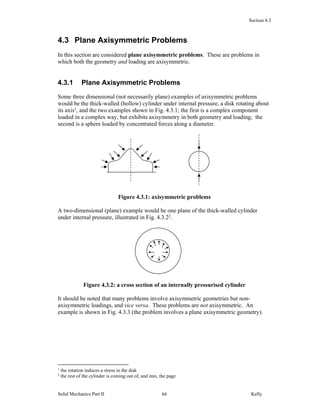
1. Section 4.3
Solid Mechanics Part II Kelly66
4.3 Plane Axisymmetric Problems
In this section are considered plane axisymmetric problems. These are problems in
which both the geometry and loading are axisymmetric.
4.3.1 Plane Axisymmetric Problems
Some three dimensional (not necessarily plane) examples of axisymmetric problems
would be the thick-walled (hollow) cylinder under internal pressure, a disk rotating about
its axis1
, and the two examples shown in Fig. 4.3.1; the first is a complex component
loaded in a complex way, but exhibits axisymmetry in both geometry and loading; the
second is a sphere loaded by concentrated forces along a diameter.
Figure 4.3.1: axisymmetric problems
A two-dimensional (plane) example would be one plane of the thick-walled cylinder
under internal pressure, illustrated in Fig. 4.3.22
.
Figure 4.3.2: a cross section of an internally pressurised cylinder
It should be noted that many problems involve axisymmetric geometries but non-
axisymmetric loadings, and vice versa. These problems are not axisymmetric. An
example is shown in Fig. 4.3.3 (the problem involves a plane axisymmetric geometry).
1
the rotation induces a stress in the disk
2
the rest of the cylinder is coming out of, and into, the page
2. Section 4.3
Solid Mechanics Part II Kelly67
Figure 4.3.3: An axially symmetric geometry but with a non-axisymmetric loading
The important characteristic of these axisymmetric problems is that all quantities, be they
stress, displacement, strain, or anything else associated with the problem, must be
independent of the circumferential variable . As a consequence, any term in the
differential equations of §4.2 involving the derivatives 22
/,/ , etc. can be
immediately set to zero.
4.3.2 Governing Equations for Plane Axisymmetric Problems
The two-dimensional strain-displacement relations are given by Eqns. 4.2.4 and these
simplify in the axisymmetric case to
r
u
r
u
r
u
r
u
r
r
r
rr
2
1
(4.3.1)
Here, it will be assumed that the displacement 0u . Cases where 0u but where the
stresses and strains are still independent of are termed quasi-axisymmetric problems;
these will be examined in a later section. Then 4.3.1 reduces to
0,,
r
rr
rr
r
u
r
u
(4.3.2)
It follows from Hooke’s law that 0 r . The non-zero stresses are illustrated in Fig.
4.3.4.
axisymmetric plane
representative of
feature
3. Section 4.3
Solid Mechanics Part II Kelly68
Figure 4.3.4: stress components in plane axisymmetric problems
4.3.3 Plane Stress and Plane Strain
Two cases arise with plane axisymmetric problems: in the plane stress problem, the
feature is very thin and unloaded on its larger free-surfaces, for example a thin disk under
external pressure, as shown in Fig. 4.3.5. Only two stress components remain, and
Hooke’s law 4.2.5a reads
rr
rrrr
E
E
1
1
or
rr
rrrr
E
E
2
2
1
1
(4.3.3)
with 0,
zzrrrzz
E
and 0zz .
Figure 4.3.5: plane stress axisymmetric problem
In the plane strain case, the strains zzz , and zr are zero. This will occur, for
example, in a hollow cylinder under internal pressure, with the ends fixed between
immovable platens, Fig. 4.3.6.
Figure 4.3.6: plane strain axisymmetric problem
rr
rr
4. Section 4.3
Solid Mechanics Part II Kelly69
Hooke’s law 4.2.5b reads
rr
rrrr
E
E
)1(
1
)1(
1
or
1
211
1
211
rr
rrrr
E
E
(4.3.4)
with rrzz .
Shown in Fig. 4.3.7 are the stresses acting in the axisymmetric plane body (with zz zero
in the plane stress case).
Figure 4.3.7: stress components in plane axisymmetric problems
4.3.4 Solution of Plane Axisymmetric Problems
The equations governing the plane axisymmetric problem are the equations of
equilibrium 4.2.3 which reduce to the single equation
0
1
rr
rr
rr
, (4.3.5)
the strain-displacement relations 4.3.2 and the stress-strain law 4.3.3-4.
Taking the plane stress case, substituting 4.3.2 into the second of 4.3.3 and then
substituting the result into 4.3.5 leads to (with a similar result for plane strain)
0
11
22
2
u
rdr
du
rdr
ud
(4.3.6)
This is Navier’s equation for plane axisymmetry. It is an “Euler-type” ordinary
differential equation which can be solved exactly to get (see Appendix to this section,
§4.3.8)
r
CrCu
1
21 (4.3.7)
rr
rr
zz
zz
5. Section 4.3
Solid Mechanics Part II Kelly70
With the displacement known, the stresses and strains can be evaluated, and the full
solution is
221221
221221
21
1
11
,
1
11
1
,
1
1
r
C
E
C
E
r
C
E
C
E
r
CC
r
CC
r
CrCu
rr
rr
(4.3.8)
For problems involving stress boundary conditions, it is best to have simpler expressions
for the stress so, introducing new constants 1/2ECA and 12/1ECC , the
solution can be re-written as
r
E
C
rE
A
u
E
C
E
C
rE
A
E
C
rE
A
C
r
AC
r
A
zzrr
rr
1211
4
,
1211
,
1211
2
1
,2
1
22
22
(4.3.9)
Plane stress axisymmetric solution
Similarly, the plane strain solution turns out to be again 4.3.8a-b only the stresses are now
{▲Problem 1}
122122
1
21
211
,
1
21
211
C
r
C
E
C
r
C
E
rr
(4.3.10)
Then, with 1/2ECA and 2112/1 ECC , the solution can be written
as
Cr
r
A
E
u
C
r
A
E
C
r
A
E
CC
r
AC
r
A
rr
zzrr
212
11
212
11
,212
11
4,2
1
,2
1
22
22
(4.3.11)
Plane strain axisymmetric solution
The solutions 4.3.9, 4.3.11 involve two constants. When there is a solid body with one
boundary, A must be zero in order to ensure finite-valued stresses and strains; C can be
determined from the boundary condition. When there are two boundaries, both A and C
are determined from the boundary conditions.
6. Section 4.3
Solid Mechanics Part II Kelly71
4.3.5 Example: Expansion of a thick circular cylinder under
internal pressure
Consider the problem of Fig. 4.3.8. The two unknown constants A and C are obtained
from the boundary conditions
0)(
)(
b
pa
rr
rr
(4.3.12)
which lead to
02)(,2)( 22
C
b
A
bpC
a
A
a rrrr (4.3.13)
so that
rrzzrr
ab
rb
p
ab
rb
p ,
1/
1/
,
1/
1/
22
22
22
22
(4.3.14)
Cylinder under Internal Pressure
Figure 4.3.8: an internally pressurised cylinder
The stresses through the thickness of the cylinder walls are shown in Fig. 4.3.9a. The
maximum principal stress is the stress and this attains a maximum at the inner face.
For this reason, internally pressurized vessels often fail there first, with microcracks
perpendicular to the inner edge been driven by the tangential stress, as illustrated in Fig.
4.3.9b.
Note that by setting tab and taking the wall thickness to be very small, att 2
, ,
and letting ra , the solution 4.3.14 reduces to:
t
r
p
t
r
pp zzrr ,, (4.3.15)
which is equivalent to the thin-walled pressure-vessel solution, Part I, §4.5.2 (if 2/1 ,
i.e. incompressible).
r
b
a
7. Section 4.3
Solid Mechanics Part II Kelly72
Figure 4.3.9: (a) stresses in the thick-walled cylinder, (b) microcracks driven by
tangential stress
Generalised Plane Strain and Other Solutions
The solution for a pressurized cylinder in plane strain was given above, i.e. where zz was
enforced to be zero. There are two other useful situations:
(1) The cylinder is free to expand in the axial direction. In this case, zz is not forced to
zero, but allowed to be a constant along the length of the cylinder, say zz . The zz
stress is zero, as in plane stress. This situation is called generalized plane strain.
(2) The cylinder is closed at its ends. Here, the axial stresses zz inside the walls of the
tube are counteracted by the internal pressure p acting on the closed ends. The force
acting on the closed ends due to the pressure is 2
p a and the balancing axial force is
2 2
zz b a , assuming zz to be constant through the thickness. For equilibrium
2 2
/ 1
zz
p
b a
(4.3.16)
Returning to the full three-dimensional stress-strain equations (Part I, Eqns. 4.2.9), set
zzzz , a constant, and 0 yzxz . Re-labelling zyx ,, with zr ,, , and again with
0r , one has
(1 )
(1 )(1 2 )
(1 )
(1 )(1 2 )
(1 )
(1 )(1 2 )
rr rr zz
rr zz
zz zz rr
E
E
E
(4.3.17)
rr
r
br ar
zz
p
1/
2
22
ab
p
1/
1/
22
22
ab
ab
p
)a( )b(
8. Section 4.3
Solid Mechanics Part II Kelly73
Substituting the strain-displacement relations 4.3.2 into 4.3.16a-b, and, as before, using
the axisymmetric equilibrium equation 4.3.5, again leads to the differential equation 4.3.6
and the solution 1 2 /u C r C r , with 2 2
1 2 1 2/ , /rr C C r C C r , but now the
stresses are
1 2 2
1 2 2
1
1
1 2
1 1 2
1
1 2
1 1 2
2 1
1 1 2
rr zz
zz
zz zz
E
C C
r
E
C C
r
E
C
(4.3.18)
As before, to make the solution more amenable to stress boundary conditions, we let
1/2ECA and 2112/1 ECC , so that the solution is
2 2
2 2
1 1
2 , 2
1 1 2 1 1 2
1
4
1 1 2
1 1 1 1
2 1 2 , 2 1 2
1 1
2 1 2
rr zz zz
zz zz
rr
E E
A C A C
r r
E
C
A C A C
E r E r
u A Cr
E r
(4.3.19)
Generalised axisymmetric solution
For internal pressure p, the solution to 4.3.19 gives the same solution for radial and
tangential stresses as before, Eqn. 4.3.14. The axial displacement is zzz zu (to within a
constant).
In the case of the cylinder with open ends (generalized plane strain), 0zz , and one
finds from Eqn. 4.3.19 that 2 2
2 / / 1 0zz p E b a . In the case of the cylinder
with closed ends, one finds that 2 2
1 2 / / 1 0zz p E b a .
A Transversely isotropic Cylinder
Consider now a transversely isotropic cylinder. The strain-displacement relations 4.3.2
and the equilibrium equation 4.3.5 are applicable to any type of material. The stress-
strain law can be expressed as (see Part I, Eqn. 6.2.14)
zzrrzz
zzrr
zzrrrr
CCC
CCC
CCC
331313
131112
131211
(4.3.20)
9. Section 4.3
Solid Mechanics Part II Kelly74
Here, take zzzz , a constant. Then, using the strain-displacement relations and the
equilibrium equation, one again arrives at the differential equation 4.3.6 so the solution
for displacement and strain is again 4.3.8a-b. With 11122 / CCCA and
12111 2/ CCCC , the stresses can be expressed as
zzzz
zz
zzrr
C
CC
C
C
CC
r
A
CC
r
A
33
1211
13
132
132
4
2
1
2
1
(4.3.21)
The plane strain solution then follows from 0zz and the generalized plane strain
solution from 0zz . These solutions reduce to 4.3.11, 4.3.19 in the isotropic case.
4.3.6 Stress Function Solution
An alternative solution procedure for axisymmetric problems is the stress function
approach. To this end, first specialise equations 4.2.6 to the axisymmetric case:
0,,
1
2
2
rrr
rrr
(4.3.22)
One can check that these equations satisfy the axisymmetric equilibrium equation 4.3.4.
The biharmonic equation in polar coordinates is given by Eqn. 4.2.7. Specialising this to
the axisymmetric case, that is, setting 0/ , leads to
0
111
2
2
2
22
2
2
rrrrrrrrr
(4.3.23)
or
0
112
32
2
23
3
4
4
dr
d
rdr
d
rdr
d
rdr
d
(4.3.24)
Alternatively, one could have started with the compatibility relation 4.2.8, specialised that
to the axisymmetric case:
0
21
2
2
rrrrr
rr
(4.3.25)
10. Section 4.3
Solid Mechanics Part II Kelly75
and then combine with Hooke’s law 4.3.3 or 4.3.4, and 4.3.22, to again get 4.3.24.
Eqn. 4.3.24 is an Euler-type ODE and has solution (see Appendix to this section, §4.3.8)
DCrrBrrA 22
lnln (4.3.26)
The stresses then follow from 4.3.22:
CrB
r
A
CrB
r
A
rr
2ln23
2ln21
2
2
(4.3.27)
The strains are obtained from the stress-strain relations. For plane strain, one has, from
4.3.4,
212ln21243
1
212ln21241
1
2
2
CrB
r
A
E
CrB
r
A
E
rr
(4.3.28)
Comparing these with the strain-displacement relations 4.3.2, and integrating rr , one has
rCrBr
r
A
E
ru
FrCrBr
r
A
E
dru
r
rrr
212ln2121
1
212ln2121
1
(4.3.27)
To ensure that one has a unique displacement ru , one must have 0B and the constant
of integration 0F , and so one again has the solution 4.3.113
.
4.3.7 Problems
1. Derive the solution equations 4.3.11 for axisymmetric plane strain.
2. A cylindrical rock specimen is subjected to a pressure pover its cylindrical face and is
constrained in the axial direction. What are the stresses, including the axial stress, in
the specimen? What are the displacements?
3
the biharmonic equation was derived using the expression for compatibility of strains (4.3.23 being the
axisymmetric version). In simply connected domains, i.e. bodies without holes, compatibility is assured
(and indeed A and B must be zero in 4.3.26 to ensure finite strains). In multiply connected domains,
however, for example the hollow cylinder, the compatibility condition is necessary but not sufficient to
ensure compatible strains (see, for example, Shames and Cozzarelli (1997)), and this is why compatibility
of strains must be explicitly enforced as in 4.3.25
11. Section 4.3
Solid Mechanics Part II Kelly76
3. A long hollow tube is subjected to internal pressure ip and external pressures op and
constrained in the axial direction. What is the stress state in the walls of the tube?
What if ppp oi ?
4. A long mine tunnel of radius a is cut in deep rock. Before the mine is constructed the
rock is under a uniform pressure p. Considering the rock to be an infinite,
homogeneous elastic medium with elastic constants E and , determine the radial
displacement at the surface of the tunnel due to the excavation. What radial stress
Parr )( should be applied to the wall of the tunnel to prevent any such
displacement?
5. A long hollow elastic tube is fitted to an inner rigid (immovable) shaft. The tube is
perfectly bonded to the shaft. An external pressure p is applied to the tube. What are
the stresses and strains in the tube?
6. Repeat Problem 3 for the case when the tube is free to expand in the axial direction.
How much does the tube expand in the axial direction (take 0zu at 0z )?
4.3.8 Appendix
Solution to Eqn. 4.3.6
The differential equation 4.3.6 can be solved by a change of variable t
er , so that
dr
dt
r
trer t
1
,log, (4.3.28)
and, using the chain rule,
dt
du
rdt
ud
rdr
td
dt
du
dr
dt
dr
dt
dt
ud
dr
dt
dt
du
dr
d
dr
ud
dt
du
rdr
dt
dt
du
dr
du
22
2
22
2
2
2
2
2
11
1
(4.3.29)
The differential equation becomes
02
2
u
dt
ud
(4.3.30)
which is an ordinary differential equation with constant coefficients. With t
eu
, one
has the characteristic equation 012
and hence the solution
r
CrC
eCeCu tt
1
21
21
(4.3.31)
12. Section 4.3
Solid Mechanics Part II Kelly77
Solution to Eqn. 4.3.24
The solution procedure for 4.3.24 is similar to that given above for 4.3.6. Using the
substitution t
er leads to the differential equation with constant coefficients
044 2
2
3
3
4
4
dt
d
dt
d
dt
d
(4.3.32)
which, with t
e
, has the characteristic equation 02
22
. This gives the
repeated roots solution
DCeBteAt tt
22
(4.3.33)
and hence 4.3.24.