Download as PDF, PPTX

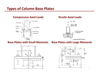

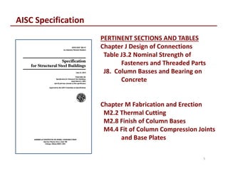


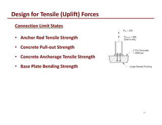


The document discusses the design and erection of column base plates. It covers types of base plates for different load cases including axial compression, tension, and combined axial and moment loads. Key topics covered include base plate and anchor rod materials, design for concrete crushing and bending, anchor rod design, and erection procedures. Diagrams illustrate critical sections and design equations for different limit states. Construction tolerances and OSHA standards for base plate design are also summarized.


![[Liang,_Qing_Quan]_Analysis_and_Design_of_Steel_an(BookZZ.org).pdf](https://cdn.slidesharecdn.com/ss_thumbnails/liangqingquananalysisanddesignofsteelanbookzz-220725050452-4cf9daa6-thumbnail.jpg?width=640&height=640&fit=bounds)


