This document contains a summary of a refresher course covering various structural analysis problems. It includes 5 situations involving calculating reactions, tensions, stresses, and shear forces for different structures. The document tests understanding through multiple choice questions after explaining the concepts and showing the calculations for each situation. The situations involve analyzing forces on a portable seat, cables supporting a ceiling, stresses on an element using Mohr's circle, forces on a bridge girder under loading, and stresses in a hollow circular signage pole.


![Situation 5 – The GERTC signage is
supported by a hallow circular pole as
shown. Given the following data:
Dimensions:
I 0.4 ]; _ 2.4 ]
ℎ 1.2 ]; 9 ]
Outside diameter of pole = 270 mm
Thickness of pole = 12 mm
Wind force acting on the signage = 5 kN
13. Determine the maximum bending stress
(MPa) in the pole due to wind force.
A. 95.4 B. 72.5 C. 79.9 D. 102.8
14. Compute the maximum longitudinal
shearing stress (MPa) in the pole due to
wind force.
A. 1.28 B. 0.87 C. 1.03 D. 1.45
15. How much is the maximum torsional
shearing stress (MPa) in the pole due to
wind force?
A. 8.9 B. 9.2 C. 7.4 D. 6.7](https://image.slidesharecdn.com/psad1-221127124504-82af4318/85/psad-1-pdf-22-320.jpg)
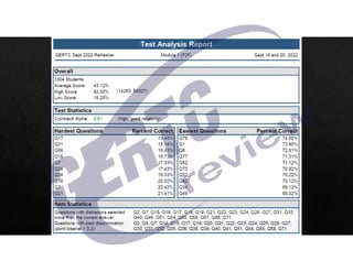
![Situation 5 – The GERTC signage is
supported by a hallow circular pole as
shown. Given the following data:
Dimensions:
I 0.4 ]; _ 2.4 ]
ℎ 1.2 ]; 9 ]
Outside diameter of pole = 270 mm
Thickness of pole = 12 mm
Wind force acting on the signage = 5 kN
13. Determine the maximum bending stress
(MPa) in the pole due to wind force.
A. 95.4 B. 72.5 C. 79.9 D. 102.8
14. Compute the maximum longitudinal
shearing stress (MPa) in the pole due to
wind force.
A. 1.28 B. 0.87 C. 1.03 D. 1.45
15. How much is the maximum torsional
shearing stress (MPa) in the pole due to
wind force?
A. 8.9 B. 9.2 C. 7.4 D. 6.7
Base of pole
#$% 5 kN
#$% 5 9.6 48 kN m
5#$% 5 1.6 8 kN m
270 mm
K 246 mm
<U()*
L
`
48 a 10b cd
e
bf cdgh fbg
:Y. Y DEF
Q13 C 24.5 22.21 35.86 16.04](https://image.slidesharecdn.com/psad1-221127124504-82af4318/85/psad-1-pdf-23-320.jpg)


![01 01 chapgere[1]](https://cdn.slidesharecdn.com/ss_thumbnails/01-01chapgere1-130611230425-phpapp02-thumbnail.jpg?width=640&height=640&fit=bounds)