This document provides information about stresses and deflections in thin cylindrical shells. It discusses the following key points:
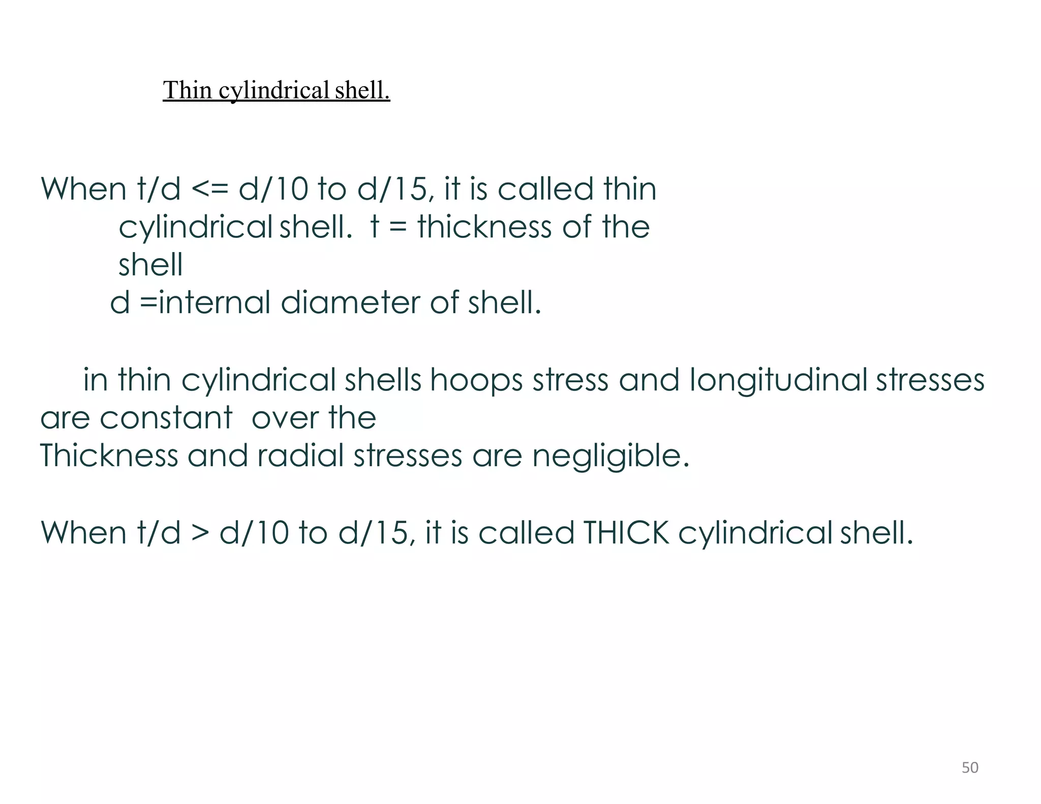
- Thin cylindrical shells have constant hoop and longitudinal stresses over the thickness, while thick shells have variable stresses.
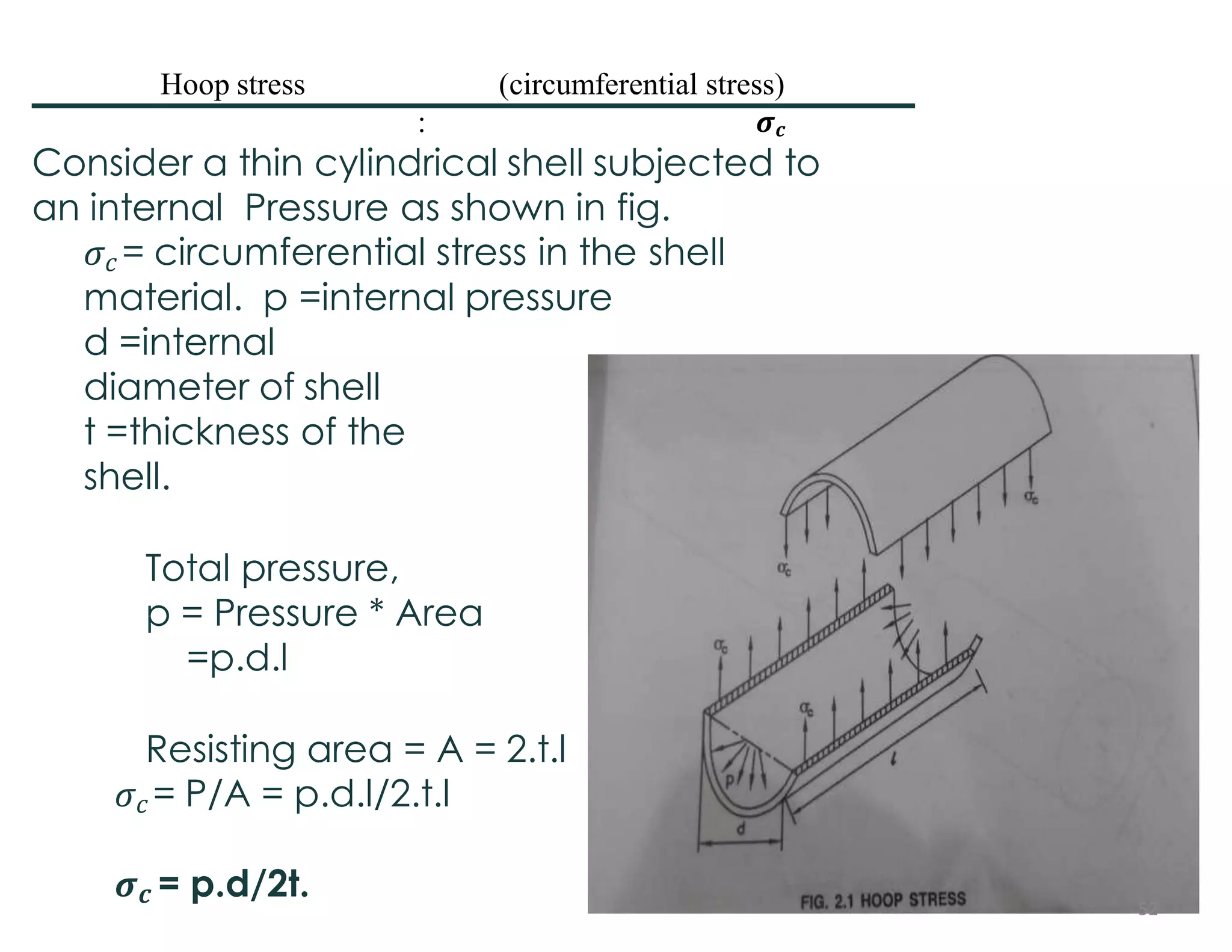
- The hoop stress in a thin cylindrical shell subjected to internal pressure is equal to pressure times internal diameter divided by 2 times thickness.
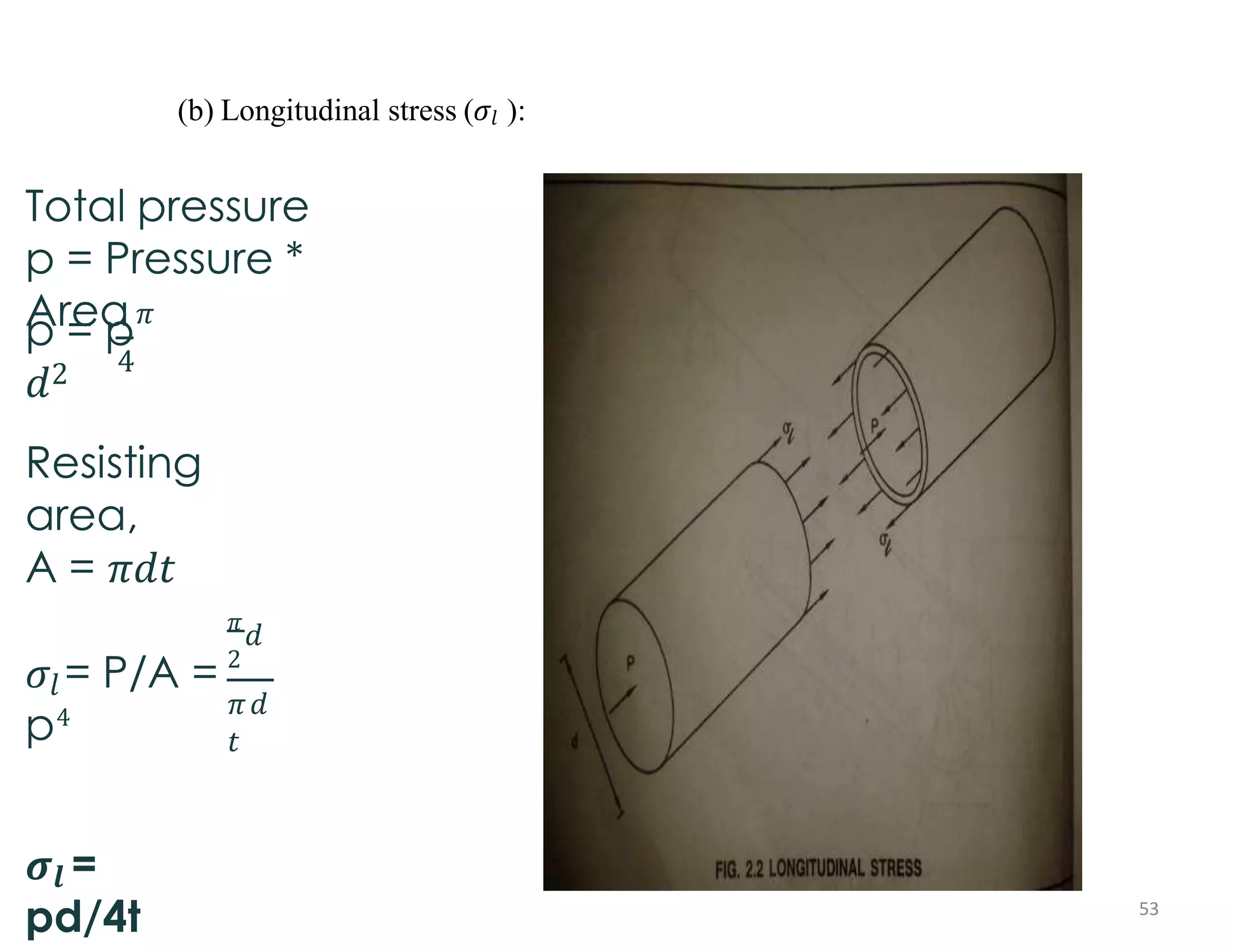
- The longitudinal stress is equal to pressure times internal diameter divided by 4 times thickness.
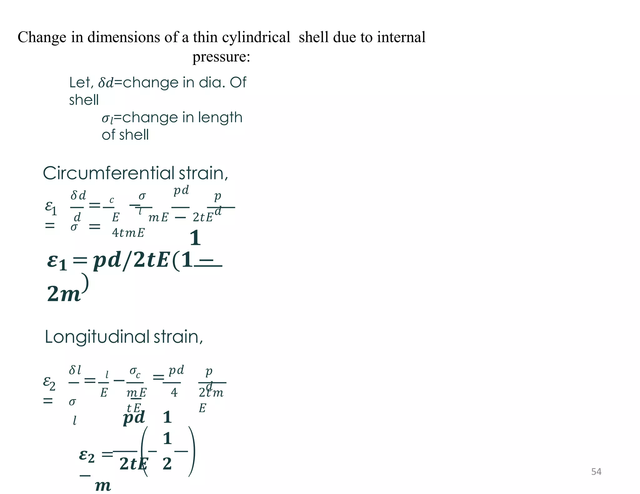
- The circumferential and longitudinal strains in a thin cylindrical shell can be calculated from the hoop and longitudinal stresses. This leads to changes in the internal diameter and length of the shell.


![Change in volume of a thin cylindrical shell due to internal pressure:
Volume of
shell,
V = 𝜋
∗ 𝑑2
∗𝑙
4
Final
volume,
4
V+𝛿𝑣 = 𝜋
𝑑 +
𝛿𝑑
2
∗
𝑙 +
𝛿𝑙
Change in
volume,
𝛿𝑣
=
𝑉 + 𝛿𝑣
− 𝑉
= [
𝜋
𝜋
4
4
2
2
𝑑 + 𝛿𝑑 ∗ (𝑙 + 𝛿𝑙)] − ∗
𝑑 ∗ 𝑙
2
2
𝜋
4
4
2
= [ 𝜋
(𝑑 + 2𝛿𝑑 ∗ 𝑑 + 𝛿𝑑 ) ∗ (𝑙 + 𝛿𝑙)]
− ∗ 𝑑
∗ 𝑙
=
𝜋 4
𝑑2𝑙 + 2𝛿𝑑 ∗ 𝑑 ∗ 𝑙 + 𝛿𝑑2 ∗ 𝑙 + 𝑑2 ∗ 𝛿𝑙 + 2𝛿𝑑 ∗ 𝑑 ∗ 𝛿𝑙
+ 𝛿𝑑2 ∗𝛿𝑙
𝜋
4
2
− 𝑑
∗ 𝑙
=
𝜋 4
𝑑2𝛿𝑙 + 2𝛿𝑑 ∗ 𝑑
∗ 𝑙
𝛿𝑣
=
𝜋
𝑉
4
4
𝑑2𝛿𝑙 + 2𝛿𝑑 ∗ 𝑑 ∗ 𝑙 /𝜋
∗
𝑑2 ∗ 𝑙
=𝛿𝑙
+ 2
𝛿𝑑
1
2
𝑑
𝑙
(𝜀 = 𝛿𝑑
, 𝜀 = 𝛿
𝑙
)
𝑙 𝑑
=𝜀2 + 2𝜀1
𝜹𝒗 =V(𝝐𝟐 + 𝟐
𝜺𝟏)
55](https://image.slidesharecdn.com/iaresomiippt-221120105045-a3acc0cf/75/IARE_SOM_II_PPT-pdf-55-2048.jpg)