Download as PDF, PPTX

![MATRUSRI
ENGINEERING COLLEGE
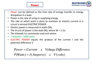
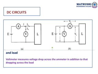
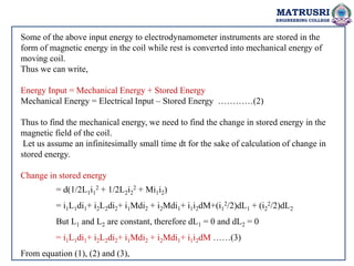
The POWER in DC circuit is
equal to the product of voltage and current.
[Power = Current × Voltage]
When the system voltage is constant, ammeter readings are almost a
sufficient indication of the POWER taken.
The POWER is calculated by using voltmeter and ammeter or wattmeter.
P = I × V = I² × R = V² / R
where:
P = power in watts (W)
I = current in amps (A)
R = resistance in ohms ( )
V = voltage in volts (V)](https://image.slidesharecdn.com/emiunit1-241126132830-23475967/85/Electrical-Measurements-Instrumentation-Electrodynamometer-Type-Instruments-5-320.jpg)

![MATRUSRI
ENGINEERING COLLEGE
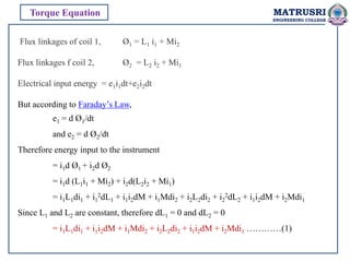
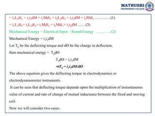
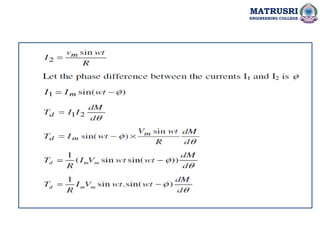
Let i1 and i2 are sinusoidal current having a phase displacement of Ø. Therefore we can write
as i1 = Im1Sinwt
i2 = Im2Sin(wt-Ø)
Thus the instantaneous deflecting torque is given as
Td = (Im1Sinwt)[ Im2Sin(wt-Ø)]dM/dƟ
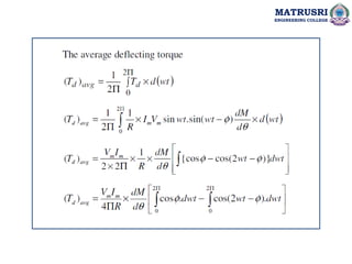
The average torque for one time period of the currents are given by
Td = (I1I2CosØ)dM/dƟ
Where I1 = RMS Value of i1
I2 = RMS value of i2
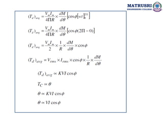
From the above two cases, we can have following conclusions:
1. For sinusoidal alternating current, the deflecting torque is determined by the product of RMS value
of coil currents and the cosine of phase angle between them.
2. When the instrument is used for AC, the instantaneous torque is proportional to i2. Thus the torque
varies as the current varies but the direction of torque remains the same. Because of the inertia of
the instrument, the needle does not follow the change in torque rather it takes a position where the
average torque becomes equal to the controlling torque.
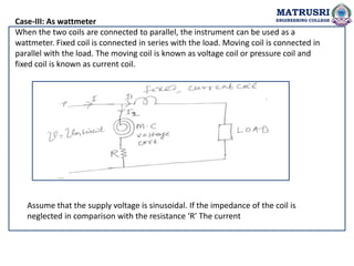
Case-2: When AC quantity is being measured.](https://image.slidesharecdn.com/emiunit1-241126132830-23475967/85/Electrical-Measurements-Instrumentation-Electrodynamometer-Type-Instruments-22-320.jpg)
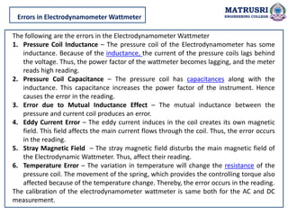
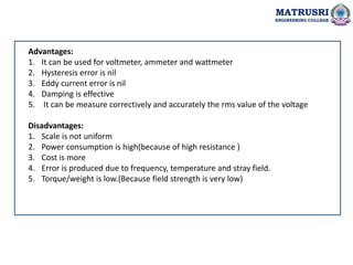


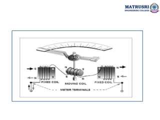
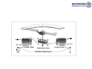
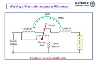
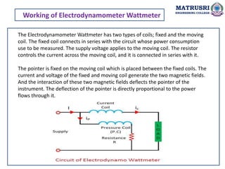
The document outlines the objectives and learning outcomes for a course on electrodynamometer type instruments at Matrusri Engineering College, covering the construction, operation, and principles of ammeters, voltmeters, and wattmeters. It explains the working of electrodynamometer wattmeters and the errors associated with their readings, alongside their advantages and disadvantages. The document emphasizes the importance of understanding electric power and its calculations in both DC and AC circuits.


![ELECTRICAL MEASUREMENT & MEASURING INSTRUMENTS [Emmi- (NEE-302) -unit-1]](https://cdn.slidesharecdn.com/ss_thumbnails/emmi-nee-302-unit-1-170607090405-thumbnail.jpg?width=640&height=640&fit=bounds)