Download as PDF, PPTX
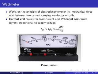
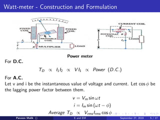
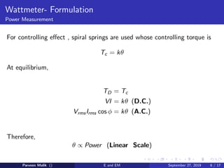
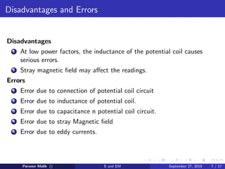
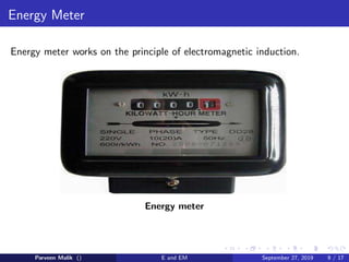
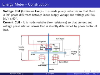
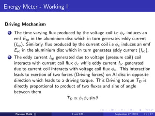

This document discusses electrical power and energy measurement techniques. It describes the construction, working principles, and sources of error for wattmeters and single-phase energy meters. Wattmeters measure power using an electrodynamic principle where the torque is proportional to the product of supply current and voltage. Single-phase energy meters use electromagnetic induction, with the driving torque proportional to supply voltage, current, and power factor, and the rotation recording consumed energy. Sources of error for both include load power factor, stray fields, temperature variations, and voltage fluctuations.


![Electricity [Mind Map]](https://cdn.slidesharecdn.com/ss_thumbnails/electricitymindmap-180501154503-thumbnail.jpg?width=640&height=640&fit=bounds)