Downloaded 303 times


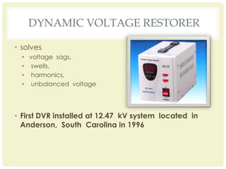
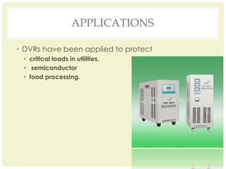

The document discusses the importance of dynamic voltage restorers (DVRs) in mitigating power quality issues like voltage sags, swells, and harmonics that can impact sensitive electronic equipment. It highlights the first DVR installation in 1996 and its capability of injecting voltage to improve stability. Caution is advised in systems with prolonged reactive power deficiencies, emphasizing the need to consider load nature and voltage supply when applying DVRs.


