Download to read offline
![MATRUSRI
ENGINEERING COLLEGE
Definitions
(a) Disruptive Discharge Voltage This is defined as the voltage which
produces the loss of dielectric strength of an insulation. It is that voltage
at which the electrical stress in the insulation causes a failure which
includes the collapse of voltage and passage of current. In solids, this
causes a permanent loss of strength, and in liquids or gases, only
temporary loss may be caused. When a discharge takes place between
two electrodes in a gas or a liquid or over a solid surface in air, it is
called flashover. If the discharge occurs through a solid insulation it is
called puncture.
(b) Withstand Voltage The voltage which has to be applied to a test
object under specified conditions in a withstand test is called the
withstand voltage [as per IS: 731 and IS: 2099–1963].
(c) Fifty Per Cent Flashover Voltage This is the voltage which has a
probability of 50% flashover, when applied to a test object. This is
normally applied in impulse test in which the loss of insulation strength
is temporary.
(d) Hundred Per Cent Flashover Voltage The voltage, that causes a
flashover at each of its applications under specified conditions, when
applied to test objects as specified, is hundred per cent flashover voltage.
(e) Creepage Distance It is the shortest distance on the contour of the
external surface of the insulator unit or between two metal fittings on
the insulator.](https://image.slidesharecdn.com/hveunit5-241023090641-f5bd4729/75/high-voltahe-testing-Insulators-Bushings-Circuit-breaker-pptx-6-2048.jpg)

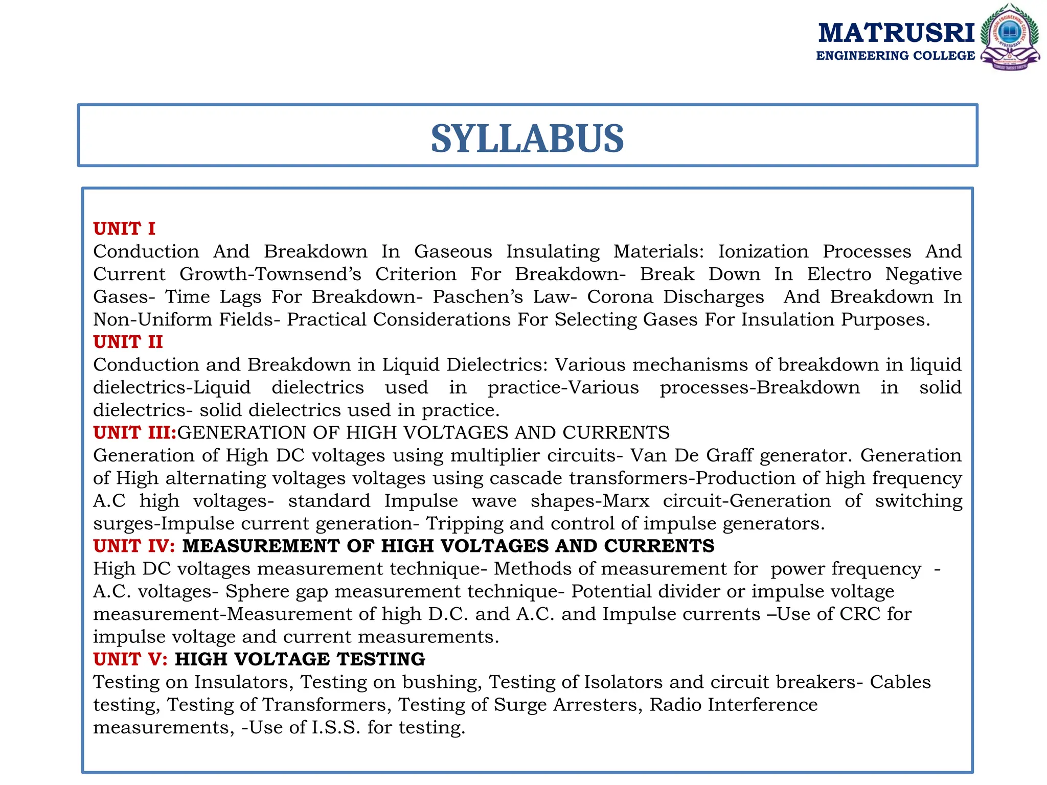
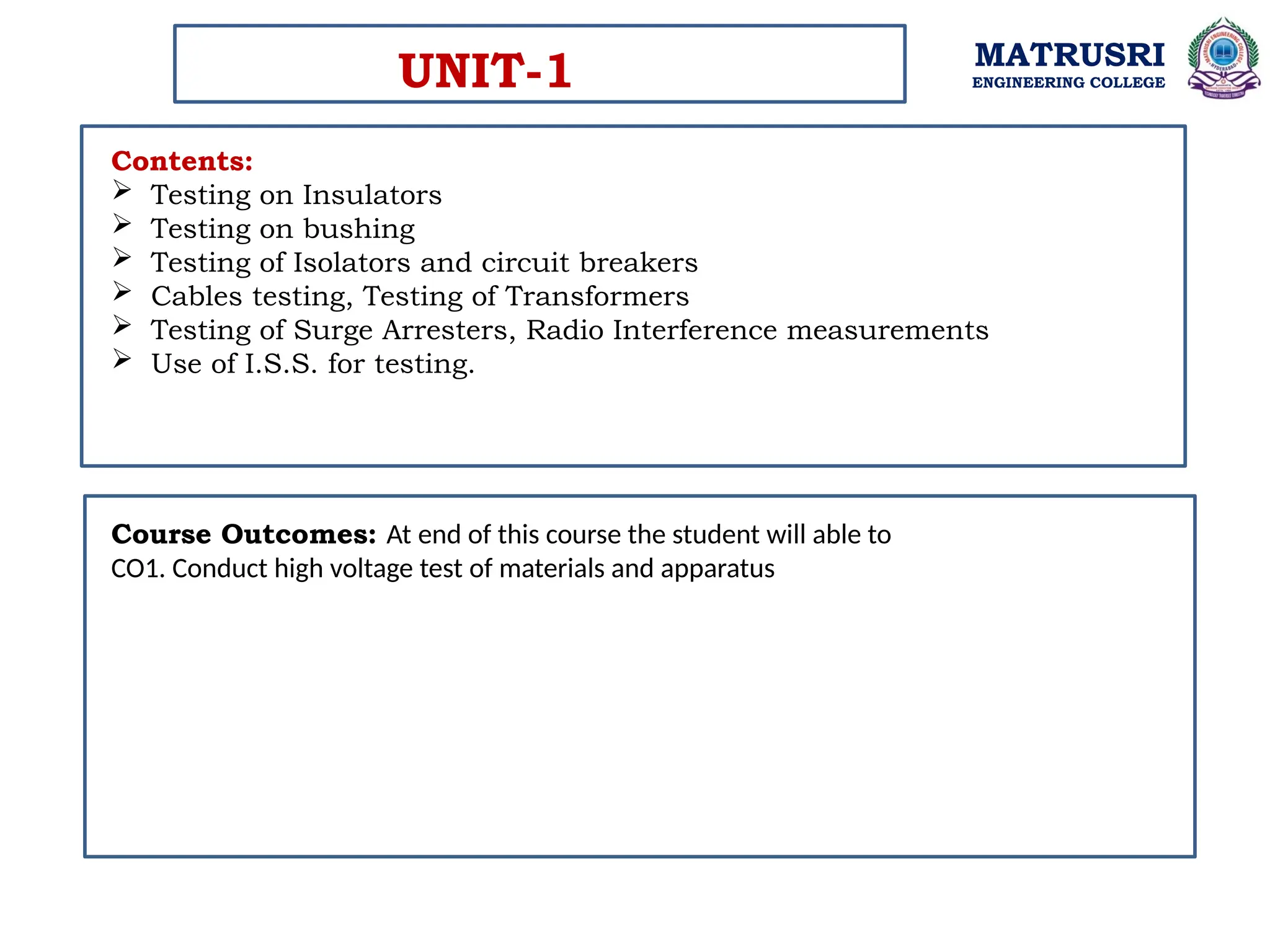
The document outlines the syllabus for a High Voltage Engineering course at Matrusri Engineering College, detailing key topics such as conduction and breakdown in gaseous and liquid dielectrics, high voltage generation and measurement, and high voltage testing methods for insulators, bushings, and circuit breakers. It emphasizes the significance of testing electrical equipment to ensure reliability and safety against overvoltages and pollution effects. Additionally, the document defines critical terms related to high voltage technology and provides insights into various testing procedures and standards.