Download to read offline
![MATRUSRI
ENGINEERING COLLEGE
• In equipments filled with a liquid dielectric (transformer, cable,
circuits breaker), heat is transferred mainly by convection.
Under natural atmospheric cooling conditions convection (N) is
given by = [ 3 / ]
𝑁 𝑓 𝐾 𝐴𝐶 𝑣 𝑛
Where K= thermal conductivity,
A = coefficient of expansion,
C= specific heat per unit volume,
𝑣 = kinetic viscosity, and = 0.25~ 0.33.
𝑛
• The main factors that control the heat transfer are thermal
conductivity K and the viscosity .
𝑣
• The higher value of K is preferable for apparatus likely to operate
continuously at a high temperature. On the other hand, a low value
of K and high viscosity can lead to localized overheating or even
electrical “burn out”. • Silicone oils do not exhibit these properties
and therefore can pose severe overheating problems in equipment
that use these oils.
Heat Transfer Characteristics](https://image.slidesharecdn.com/hveunit2-241108102527-a1f0e131/85/Conduction-and-Breakdown-in-Liquid-Dielectrics-22-320.jpg)
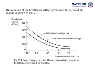
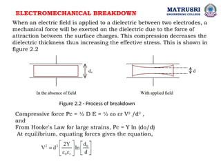
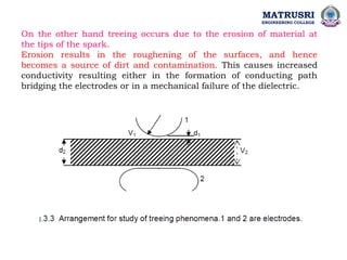
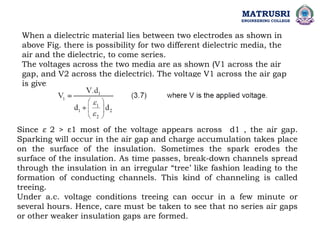
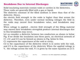

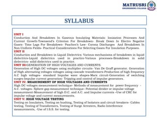
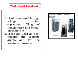
The document outlines the syllabus for a high voltage engineering course at Matrusri Engineering College, focusing on conduction and breakdown in liquid dielectrics, including their mechanisms, applications, and testing methods. It discusses the properties and advantages of liquid dielectrics, common types used in practice, and factors influencing their effectiveness as insulation materials. Additionally, the document covers high voltage generation and measurement techniques, as well as the importance of liquid purification to maintain their dielectric strength.