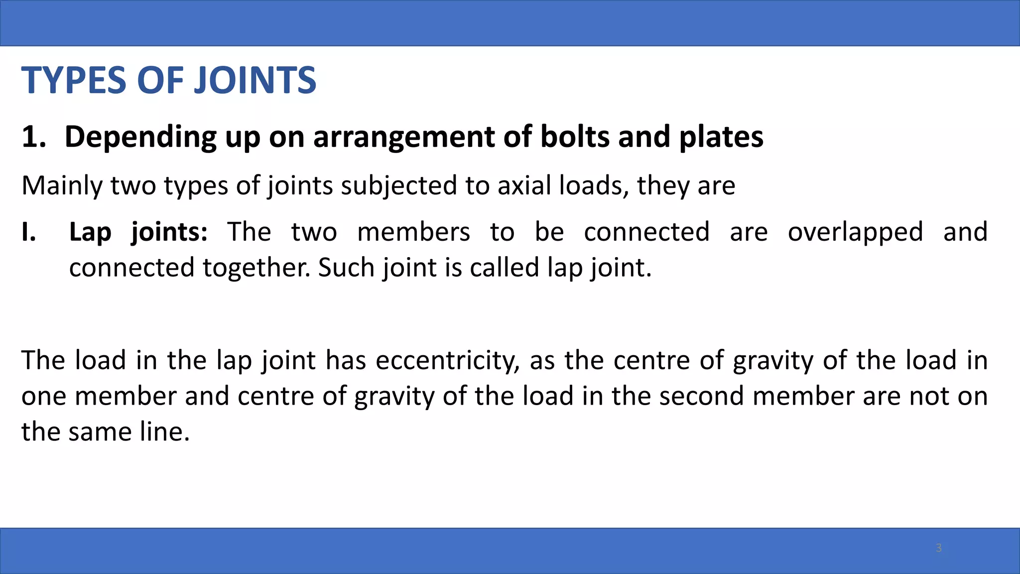
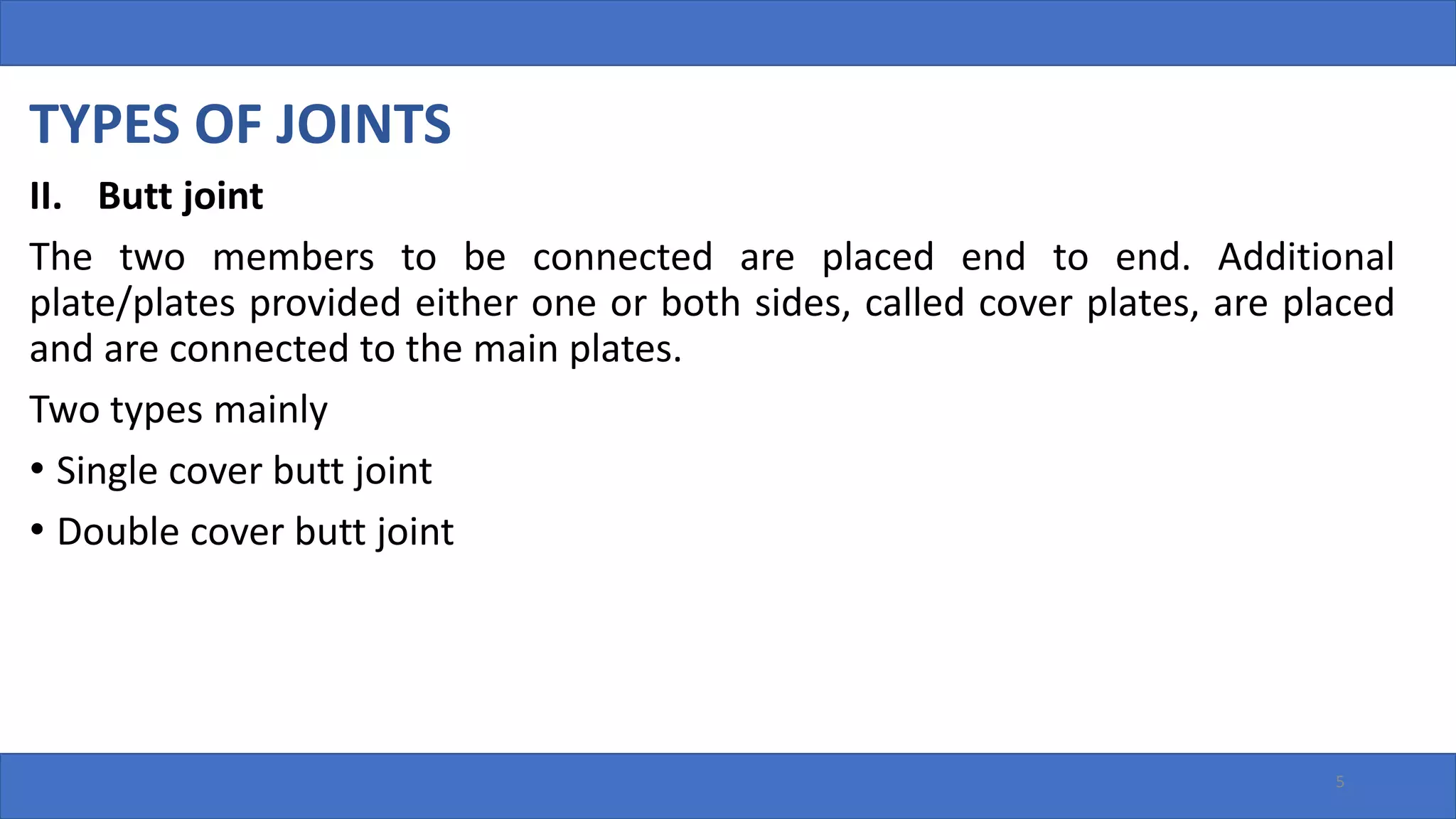
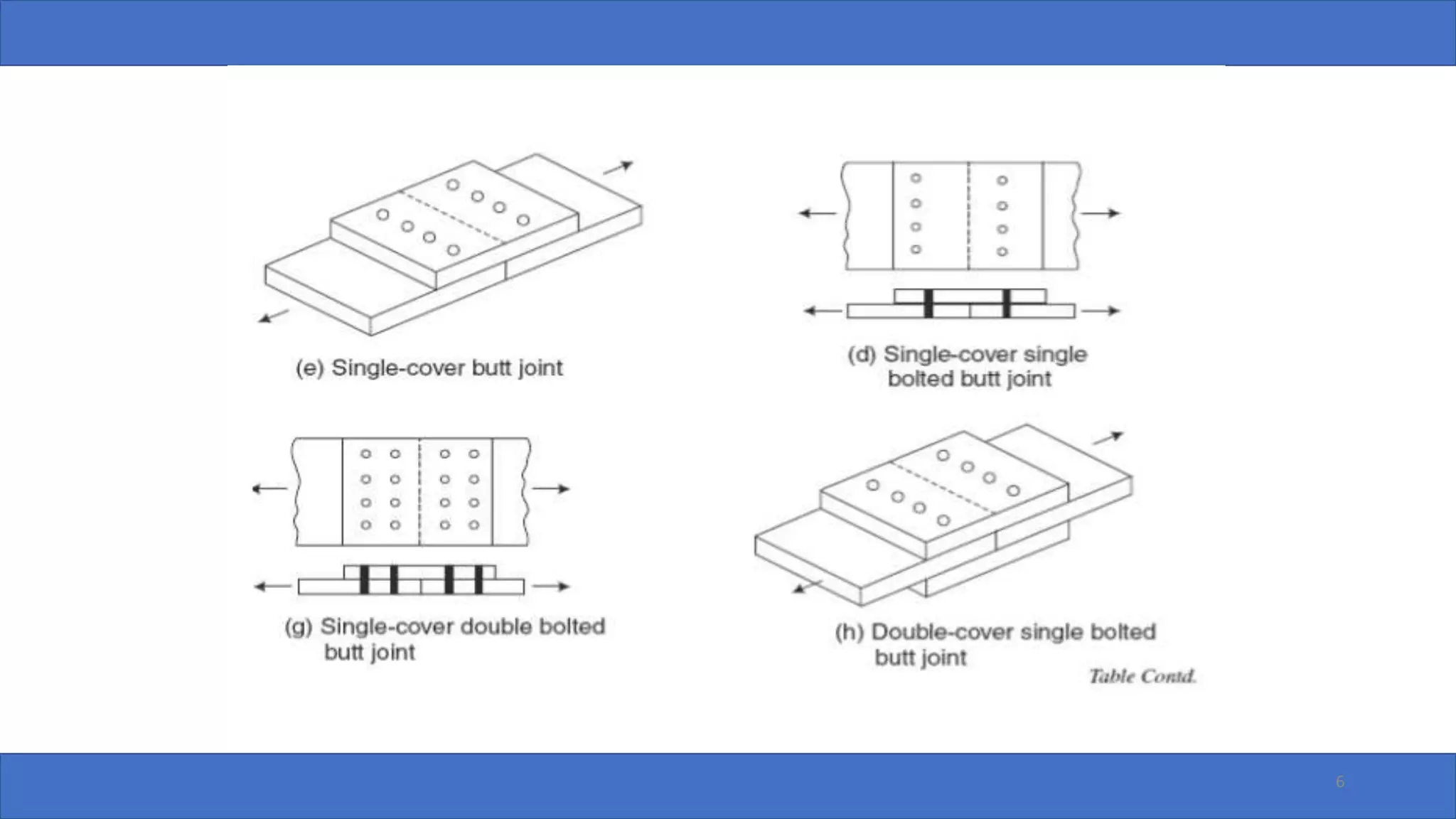
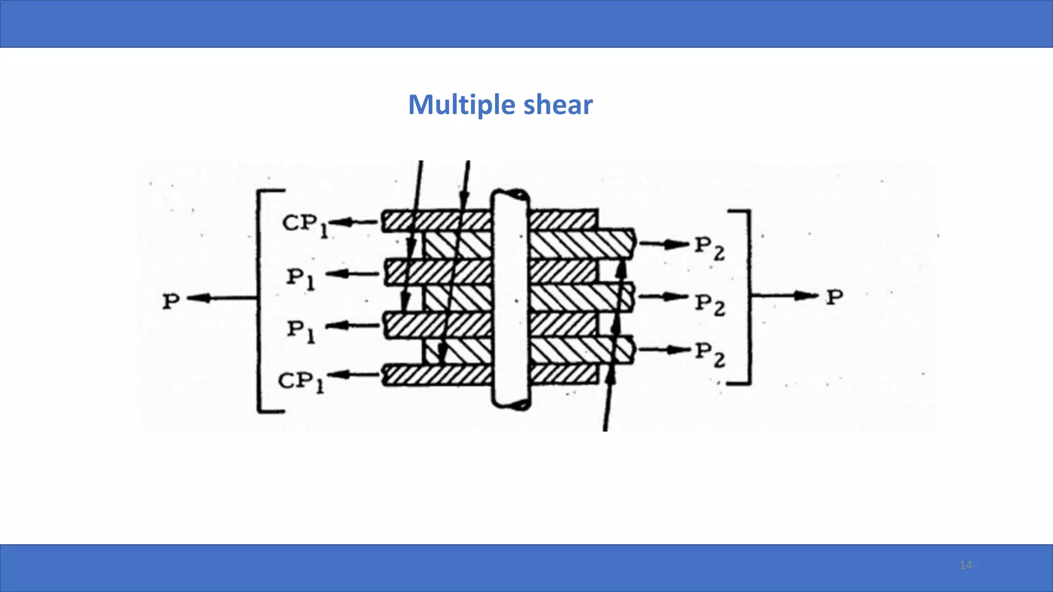
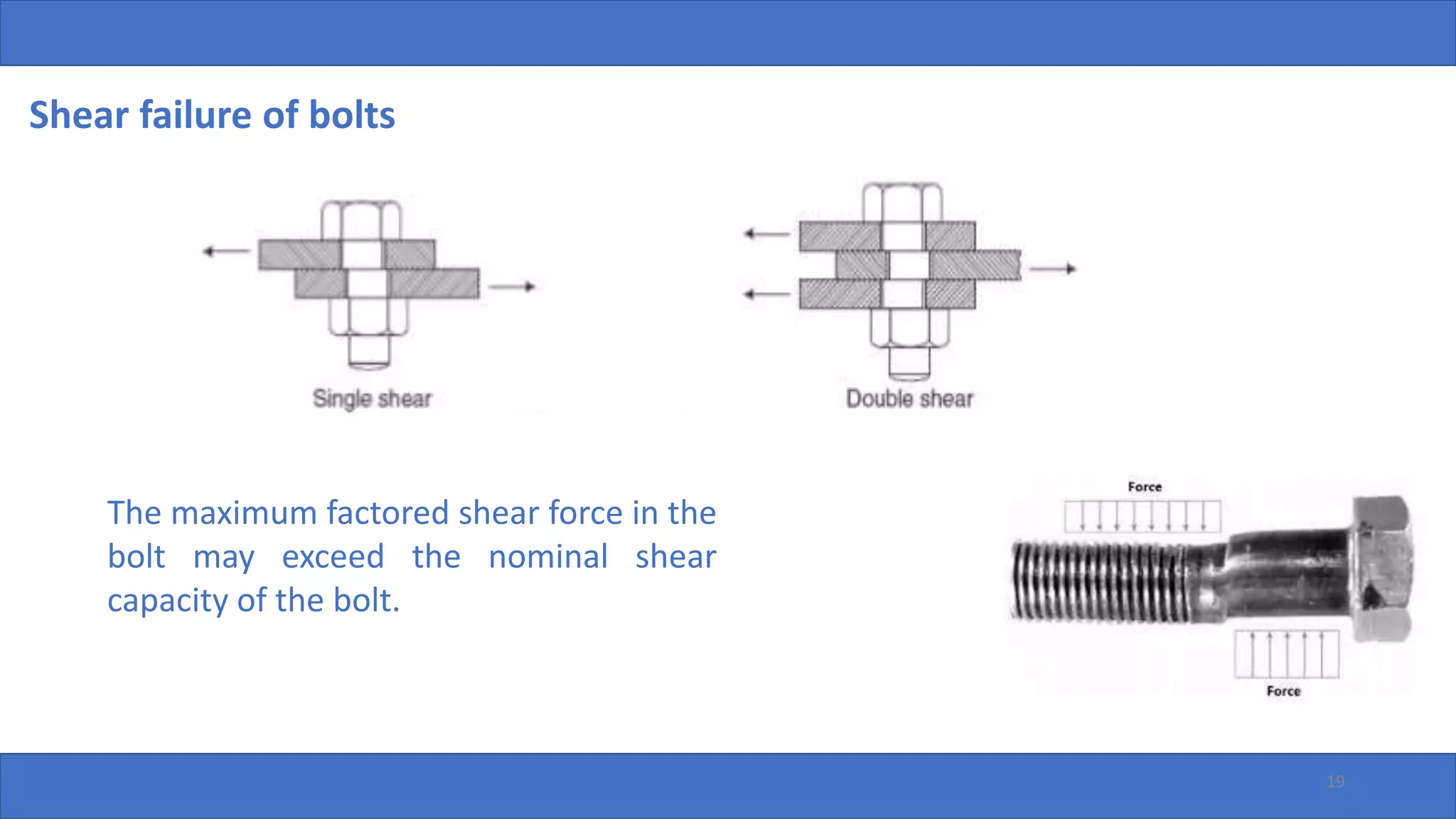
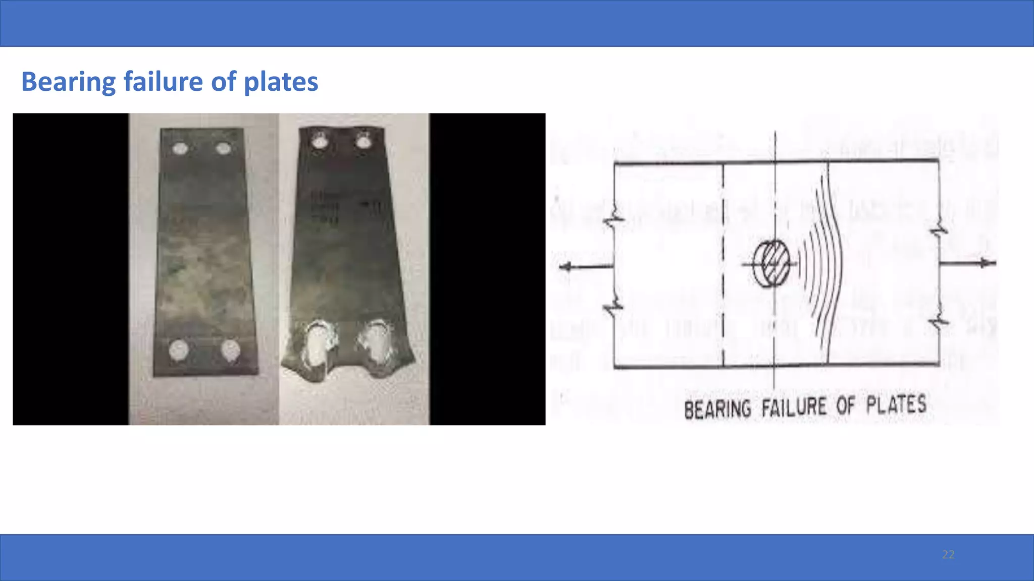
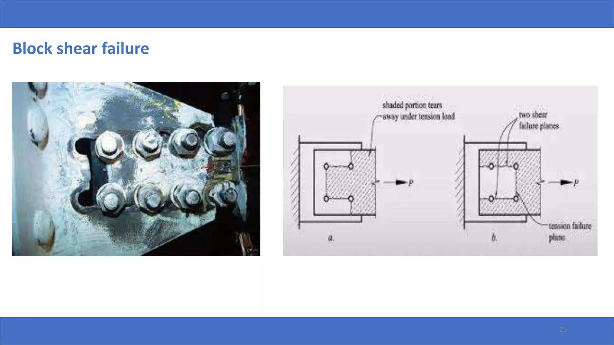
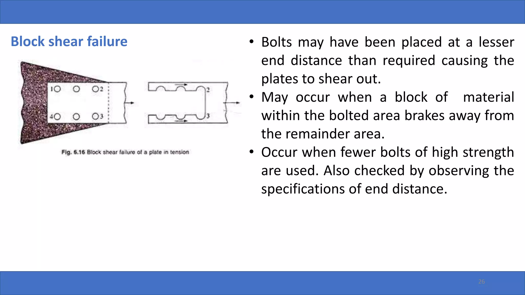
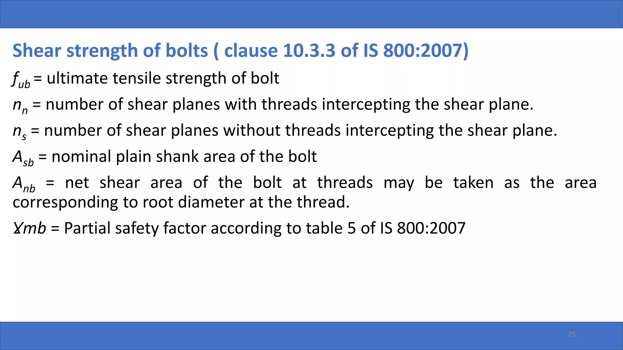
2. TYPES OF JOINTS
1. Depending up on arrangement of bolts and plates
2. Depending up on the mode of load transmission
3. Depending up on nature and location of load
2
3. TYPES OF JOINTS
1. Depending up on arrangement of bolts and plates
Mainly two types of joints subjected to axial loads, they are
I. Lap joints: The two members to be connected are overlapped and
connected together. Such joint is called lap joint.
The load in the lap joint has eccentricity, as the centre of gravity of the load in
one member and centre of gravity of the load in the second member are not on
the same line.
3
5. TYPES OF JOINTS
II. Butt joint
The two members to be connected are placed end to end. Additional
plate/plates provided either one or both sides, called cover plates, are placed
and are connected to the main plates.
Two types mainly
• Single cover butt joint
• Double cover butt joint
5
8. 8
It is more desirable to provide butt joint rather than a lap joint for snug-
tight bolts because
1. In the case of a double cover butt joint, the total shear force to be
transmitted by the members is split into two parts so shear carrying
capacity of a bolt in a double cover butt joint is double that of bolt in lap
joint.
2. Eccentricity of forces does not exist in butt joint and hence bending is
eliminated.
15. TYPES OF JOINTS
3. Depending up on the nature and location of load
a) Direct shear connections
b) Eccentric connections
c) Moment shear connections
15
18. Failure of bolted joints
Following are the failure modes of bolted joints
• Shear failure of bolts
• Bearing failure of bolts
• Tensile failure of bolts
• Shear failure of plate
• Bearing failure of plate
• Tensile failure of plate
18
19. Shear failure of bolts
19
The maximum factored shear force in the
bolt may exceed the nominal shear
capacity of the bolt.
20. Bearing failure of bolts
20
The bolt is crushed around half
circumference. The plate may be strong in
bearing and the heaviest stressed plate
may press the bolt shank.
Plates are made of high
strength steel and
Bolts are made of very low
grade steel
23. When an ordinary bolt is subjected to shear forces, slip takes place and bolt
comes in contact with the plates. The plate may get crushed if the plate
material is weaker than the bolt material.
The bolt spacing and end distance will influence the bearing strength. So
adhere to the codal provisions of bolt spacing, end distance, max pitch etc.
23
24. Tension or tearing failure of plates
24
Tension failure occurs because
when the bolts are stronger than
the plates. Tension both the
gross area and net effective area
must be considered.
26. Block shear failure
26
• Bolts may have been placed at a lesser
end distance than required causing the
plates to shear out.
• May occur when a block of material
within the bolted area brakes away from
the remainder area.
• Occur when fewer bolts of high strength
are used. Also checked by observing the
specifications of end distance.
27. Design strength of ordinary black bolts ( clause 10.3 of IS 800:2007)
The strength of an ordinary bolt is minimum of strength of bolts in shear,
bearing and tension. (As discussed in the failure of joints)
No of bolts required =
Factored load transmitted through the joint
𝑆𝑡𝑟𝑒𝑛𝑔𝑡ℎ 𝑜𝑓 𝑎 𝑠𝑖𝑛𝑔𝑙𝑒 𝑏𝑜𝑙𝑡
However failure of a joint can be in bolt or plate. Thus the strength of a joint
will be minimum of strength of joint on the basis of strength of bolts in the
joint and net tensile strength of the plate.
27
28. Shear strength of bolts ( clause 10.3.3 of IS 800:2007)
The design strength of the bolt, Vdsb as governed shear strength is given by
Vdsb =
𝑉 𝑛𝑠𝑏
γ 𝑚𝑏
Vnsb = Nominal shear capacity of a bolt
=
𝑓𝑢𝑏
3
𝑛 𝑛 𝐴 𝑛𝑏 + 𝑛𝑠𝐴 𝑠𝑏
28
29. Shear strength of bolts ( clause 10.3.3 of IS 800:2007)
fub = ultimate tensile strength of bolt
nn = number of shear planes with threads intercepting the shear plane.
ns = number of shear planes without threads intercepting the shear plane.
Asb = nominal plain shank area of the bolt
Anb = net shear area of the bolt at threads may be taken as the area
corresponding to root diameter at the thread.
Ɣmb = Partial safety factor according to table 5 of IS 800:2007
29