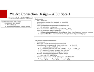
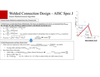
The document provides an overview of welded connection design according to the American Institute of Steel Construction (AISC) Specification J. It lists relevant AISC specifications and codes for welding design. Tables are presented covering effective throat sizes of welds, minimum fillet weld sizes, and available strength of welded joints. General information is given on fillet weld sizing, strength, and design considerations for loaded welds, eccentrically loaded weld groups, and various welded connection types. Methods for analyzing welded connections using the elastic method, instantaneous center of rotation method, and simplified approaches are summarized.

![Welded Connection Design – AISC Spec J
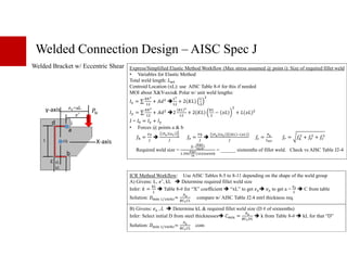
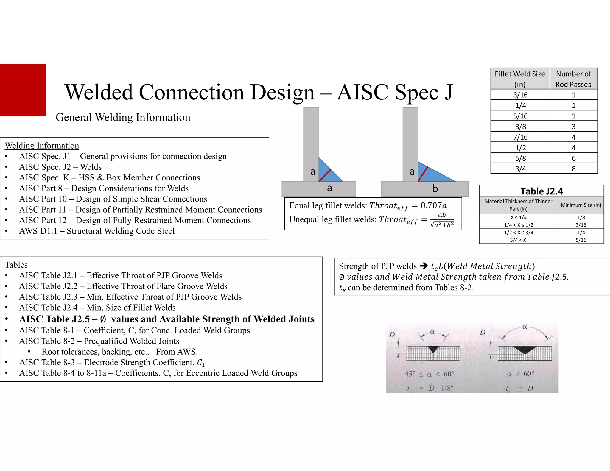
Loaded Fillet Welds
Transverse/Angled Loading of Fillet Welds
• J2.4 allows transverse loading allows an increase of strength
• A) For a linear weld group w/ uniform leg size, loaded through
center of gravity,
;+ = <+3@3 w/ ∅ = 0.75
<+3 = 0.60<DEE 1.0 + 0.50 H .]
] measured off longitudinal axis.
• B) For weld elements analyzed w/ ICR, ;+^ , ;+_ , & + are
permitted to be determined as given on AISC pg 16.1-116
• C) Fillet weld groups concentrically loaded w/ longitudinal and
transverse elements. ;+= greater of: w/ ∅ = 0.75
1. ;+ = ;+3` + ;+3O
Or
2. ;+ = 0.85;+3` + 1.5;+3O
Note: Don’t use <+3 = 0.60<DEE 1.0 + 0.50 H .] for
these cases b/c transverse & longitudinal fillet welds have
different deformation properties and limits. Use
;+3`&;+3O = <3@3
<3 commonly 0.60<DEE & @3 0.707 G
&
∅
A) C)](https://image.slidesharecdn.com/weldportion-230403123913-b35769b3/85/Weld_Portion-pdf-3-320.jpg)
![Welded Connection Design – AISC Spec J
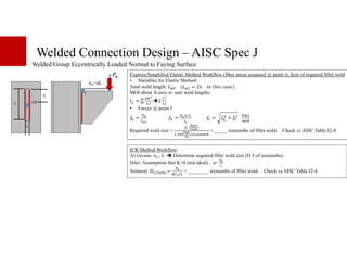
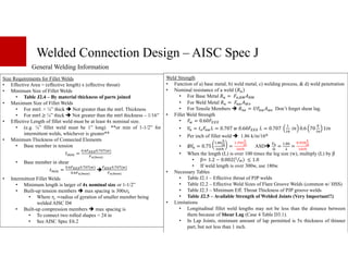
Loaded Angle/Truss Member
Angle to Plate Welded Connections
• Prescribing welds balanced about the neutral axis
• Weld group centroid coincides w/ centroid of tensile load.
S
c
d
Nominal Tensile Capacity of member with lower @e
;f = G " ∅g+ = ∅<_@e w/∅ = 0.9
∅g+ = ∅<f@ w/∅ = 0.75 & @ = B@+
Consider shear lag from Table 4.1 case 2 or 4. Some
apply U=0.87 up front (case 4)
+e`
A
Block Shear:
;+ = 0.6<
f@+i + B :<
f@+O ≤ 0.6<
_@ei + B :<
f@+O [AISC J4-5]
B : = 1 when tension stress is uniform, 0.85 otherwise
@+i = #H $j k = 3 :
@+O = #H $j k H = ( +e` ` e)( : )
∅lm = 0.75lm ≥ ln opqor
s tm uvwx y vz {tms |wqs qwm}v~
•` O
A
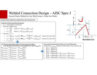
Plate-to-Plate
Method 1: Shear Lag Up Front Method 2: Shear Lag to Lengthen Welds
at the end (preferred b/c accurate U factor)
;f = G " ∅g+ = ∅<_@e w/∅ = 0.9
Select Fillet Weld Size & total length 3
assuming U=1.0
Take Moment about “Point A“
;f c
d − +e` gS = 0
S,€ `€ =
•
A `‚ ƒO„. • „ *+€P
,€ `€ = 3 − S,€ `€
Shear Lag Factor Higher of Case 2 or 4
(Case 2 & 4 evaluated w/ longer weld)
,„ … =
X†,‡7ˆ‡
‰ S,„ …=
X ,‡7ˆ‡
‰
Select Fillet Weld Size & total length 3
Take Moment about “Point A“
;f c
d − +e` gS = 0
S,€ `€ =
•
A `‚ ƒO„. • „ *+€P
,€ `€ = 3 − S,€ `€
U to Lengthen Welds @ end (preferred b/c accurate U factor)
;f = G " ∅g+ = ∅<_@e w/∅ = 0.9
Select Fillet Weld Size & total length 3
assuming U=1.0 3 = 2
Shear Lag Factor from Case 4
,„ … =
,€ `€
B](https://image.slidesharecdn.com/weldportion-230403123913-b35769b3/85/Weld_Portion-pdf-4-320.jpg)