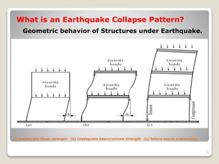
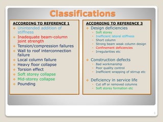
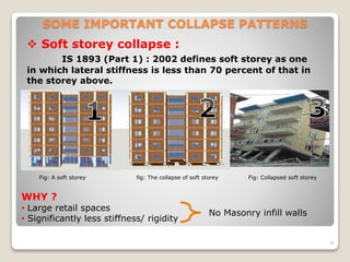
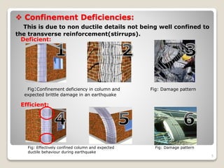
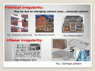
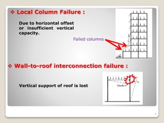
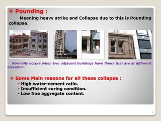
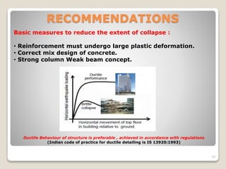
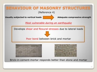
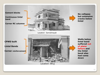
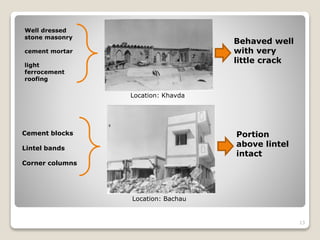
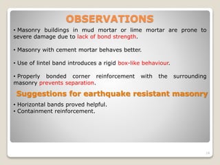
K.L.E Society’s
Dr. M. S. Sheshgiri College of Engineering
& Technology, Belagavi
Department of Civil Engineering
Seminar on : Earthquake Collapse
Patterns and their reasons
By Pakjum Nyori
(M.Tech. IInd Sem Structural Engg.)
Under the Guidance of Dr. Kishore Kulkarni
1
a) Inadequate Shear strength (b) Inadequate beam/column strength (c) failure due to overturning
What is an Earthquake Collapse Pattern?
Geometric behavior of Structures under Earthquake.
2
Classifications
ACCORDING TO REFERENCE 1
 Unintended addition of
stiffness
 Inadequate beam-column
joint strength
 Tension/compression failures
 Wall to roof interconnection
failure
 Local column failure
 Heavy floor collapse
 Torsion effect
 Soft storey collapse
 Mid-storey collapse
 Pounding
ACCORDING TO REFERENCE 3
 Design deficiencies
• Soft storey
• Inefficient lateral stiffness
• Short column
• Strong beam weak column design
• Confinement deficiencies
• Irregularities etc
 Construction defects
• Bad workmanship
• Poor quality control
• Inefficient wrapping of stirrup etc
 Deficiency in service life
• Cut off or removed columns
• Soft storey formation etc
3
SOME IMPORTANT COLLAPSE PATTERNS
4
 Soft storey collapse :
IS 1893 (Part 1) : 2002 defines soft storey as one
in which lateral stiffness is less than 70 percent of that in
the storey above.
Fig: A soft storey fig: The collapse of soft storey Fig: Collapsed soft storey
WHY ?
• Large retail spaces
• Significantly less stiffness/ rigidity
No Masonry infill walls
 Confinement Deficiencies:
This is due to non ductile details not being well confined to
the transverse reinforcement(stirrups).
5
Deficient:
Efficient:
Fig:Confinement deficiency in column and Fig: Damage pattern
expected brittle damage in an earthquake
Fig: Effectively confined column and expected Fig: Damage pattern
ductile behaviour during earthquake
Vertical irregularity:
May be due to changing column axes , removed column.
6
Fig : Changing column axe Fig: Removed column Fig: Collapse pattern
Planar irregularity:
Fig: Irregular plan
Fig : Damage pattern
Unintended addition of stiffness :
Reduced effective length of columns , thereby increasing
its stiffness in terms of lateral forces.
7
The column in this case attracts larger horizontal shear
forces than its capacity.
Since, Stiffness is proportional to applied force.
 Local Column Failure :
Due to horizontal offset
or insufficient vertical
capacity.
8
Failed columns
 Wall-to-roof interconnection failure :
Vertical support of roof is lost
 Pounding :
Meaning heavy strike and Collapse due to this is Pounding
collapse.
9
Normally occurs when two adjacent buildings have floors that are at different
elevation.
 Some Main reasons for all these collapse :
• High water-cement ratio.
• Insufficient curing condition.
• Low fine aggregate content.
RECOMMENDATIONS
10
Basic measures to reduce the extent of collapse :
• Reinforcement must undergo large plastic deformation.
• Correct mix design of concrete.
• Strong column Weak beam concept.
Ductile Behaviour of structure is preferable , achieved in accordance with regulations
(Indian code of practice for ductile detailing is IS 13920:1993)
BEHAVIOUR OF MASONRY STRUCTURES
11
(Reference 4)
Usually subjected to vertical loads Adequate compressive strength
Most vulnerable during an earthquake
Develops shear and flexural stresses due to lateral loads
Poor bond between brick and mortar
Brick-in-cement-mortar responds better than stone and mortar
Cement blocks
Continuous lintel
band
Corner RC columns
12
No collapse
but extensive
cracks below
lintel
Location: Samakhayali
CPWD built
Lintel Bands
Corner reinforcement
Walls below
lintel band
suffered out
of plane
failure and
the lintel
band also
had come
down
Location: Bhuj
Well dressed
stone masonry
cement mortar
light
ferrocement
roofing
13
Behaved well
with very
little crack
Location: Khavda
Cement blocks
Lintel bands
Corner columns
Portion
above lintel
intact
Location: Bachau
OBSERVATIONS
14
• Masonry buildings in mud mortar or lime mortar are prone to
severe damage due to lack of bond strength.
• Masonry with cement mortar behaves better.
• Use of lintel band introduces a rigid box-like behaviour.
• Properly bonded corner reinforcement with the surrounding
masonry prevents separation.
Suggestions for earthquake resistant masonry
• Horizontal bands proved helpful.
• Containment reinforcement.
References:
1. Reinforced concrete design of tall buildings(textbook) by Bungale S.
Taranath, Ph.D. 2010.
2. classifications of structural types and damage patterns of buildings for
earthquake field investigation. shigeyuki OKADA and nobuo TAKAI.
Sapporo, Japan.
3. The Reasons and Results of earthquake damages in Reinforced Concrete
Buildings. Z. Canan Girgin and D. Gunes Yilmaz.YTU Turkey.
4. Behavior of masonry structures during the Bhuj Earthquake 2001.K S
Jagadish, S Raghunath and K S Nanjunda Rao. September 2003.
5. Observations from the Bhuj Earthquake of January 26 2001 By
S.K. Ghosh, Ph. D. President S.K. Ghosh Associates Inc. Northbrook, IL.
15
THANK YOU
16

Earthquake collapse pattern

  • 1.
    K.L.E Society’s Dr. M.S. Sheshgiri College of Engineering & Technology, Belagavi Department of Civil Engineering Seminar on : Earthquake Collapse Patterns and their reasons By Pakjum Nyori (M.Tech. IInd Sem Structural Engg.) Under the Guidance of Dr. Kishore Kulkarni 1
  • 2.
    a) Inadequate Shearstrength (b) Inadequate beam/column strength (c) failure due to overturning What is an Earthquake Collapse Pattern? Geometric behavior of Structures under Earthquake. 2
  • 3.
    Classifications ACCORDING TO REFERENCE1  Unintended addition of stiffness  Inadequate beam-column joint strength  Tension/compression failures  Wall to roof interconnection failure  Local column failure  Heavy floor collapse  Torsion effect  Soft storey collapse  Mid-storey collapse  Pounding ACCORDING TO REFERENCE 3  Design deficiencies • Soft storey • Inefficient lateral stiffness • Short column • Strong beam weak column design • Confinement deficiencies • Irregularities etc  Construction defects • Bad workmanship • Poor quality control • Inefficient wrapping of stirrup etc  Deficiency in service life • Cut off or removed columns • Soft storey formation etc 3
  • 4.
    SOME IMPORTANT COLLAPSEPATTERNS 4  Soft storey collapse : IS 1893 (Part 1) : 2002 defines soft storey as one in which lateral stiffness is less than 70 percent of that in the storey above. Fig: A soft storey fig: The collapse of soft storey Fig: Collapsed soft storey WHY ? • Large retail spaces • Significantly less stiffness/ rigidity No Masonry infill walls
  • 5.
     Confinement Deficiencies: Thisis due to non ductile details not being well confined to the transverse reinforcement(stirrups). 5 Deficient: Efficient: Fig:Confinement deficiency in column and Fig: Damage pattern expected brittle damage in an earthquake Fig: Effectively confined column and expected Fig: Damage pattern ductile behaviour during earthquake
  • 6.
    Vertical irregularity: May bedue to changing column axes , removed column. 6 Fig : Changing column axe Fig: Removed column Fig: Collapse pattern Planar irregularity: Fig: Irregular plan Fig : Damage pattern
  • 7.
    Unintended addition ofstiffness : Reduced effective length of columns , thereby increasing its stiffness in terms of lateral forces. 7 The column in this case attracts larger horizontal shear forces than its capacity. Since, Stiffness is proportional to applied force.
  • 8.
     Local ColumnFailure : Due to horizontal offset or insufficient vertical capacity. 8 Failed columns  Wall-to-roof interconnection failure : Vertical support of roof is lost
  • 9.
     Pounding : Meaningheavy strike and Collapse due to this is Pounding collapse. 9 Normally occurs when two adjacent buildings have floors that are at different elevation.  Some Main reasons for all these collapse : • High water-cement ratio. • Insufficient curing condition. • Low fine aggregate content.
  • 10.
    RECOMMENDATIONS 10 Basic measures toreduce the extent of collapse : • Reinforcement must undergo large plastic deformation. • Correct mix design of concrete. • Strong column Weak beam concept. Ductile Behaviour of structure is preferable , achieved in accordance with regulations (Indian code of practice for ductile detailing is IS 13920:1993)
  • 11.
    BEHAVIOUR OF MASONRYSTRUCTURES 11 (Reference 4) Usually subjected to vertical loads Adequate compressive strength Most vulnerable during an earthquake Develops shear and flexural stresses due to lateral loads Poor bond between brick and mortar Brick-in-cement-mortar responds better than stone and mortar
  • 12.
    Cement blocks Continuous lintel band CornerRC columns 12 No collapse but extensive cracks below lintel Location: Samakhayali CPWD built Lintel Bands Corner reinforcement Walls below lintel band suffered out of plane failure and the lintel band also had come down Location: Bhuj
  • 13.
    Well dressed stone masonry cementmortar light ferrocement roofing 13 Behaved well with very little crack Location: Khavda Cement blocks Lintel bands Corner columns Portion above lintel intact Location: Bachau
  • 14.
    OBSERVATIONS 14 • Masonry buildingsin mud mortar or lime mortar are prone to severe damage due to lack of bond strength. • Masonry with cement mortar behaves better. • Use of lintel band introduces a rigid box-like behaviour. • Properly bonded corner reinforcement with the surrounding masonry prevents separation. Suggestions for earthquake resistant masonry • Horizontal bands proved helpful. • Containment reinforcement.
  • 15.
    References: 1. Reinforced concretedesign of tall buildings(textbook) by Bungale S. Taranath, Ph.D. 2010. 2. classifications of structural types and damage patterns of buildings for earthquake field investigation. shigeyuki OKADA and nobuo TAKAI. Sapporo, Japan. 3. The Reasons and Results of earthquake damages in Reinforced Concrete Buildings. Z. Canan Girgin and D. Gunes Yilmaz.YTU Turkey. 4. Behavior of masonry structures during the Bhuj Earthquake 2001.K S Jagadish, S Raghunath and K S Nanjunda Rao. September 2003. 5. Observations from the Bhuj Earthquake of January 26 2001 By S.K. Ghosh, Ph. D. President S.K. Ghosh Associates Inc. Northbrook, IL. 15
  • 16.