Downloaded 521 times

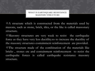
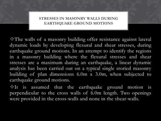
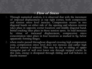
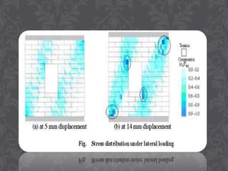
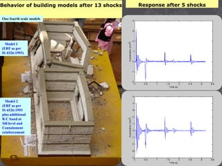
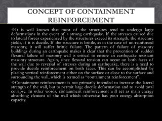
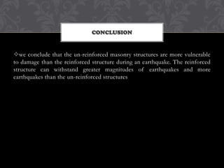


This presentation discusses how to make masonry structures more resistant to earthquakes. It defines earthquake resistant masonry structures as those built from brick, stone or other masonry materials combined with containment reinforcement. It describes stresses in masonry walls during quakes and modeling of walls, then discusses techniques to strengthen buildings like adding flexibility, reinforcing walls and foundations, and containment reinforcement around walls. Shock table testing was also used to evaluate different earthquake resistant building features in masonry models.


