Download as PDF, PPTX
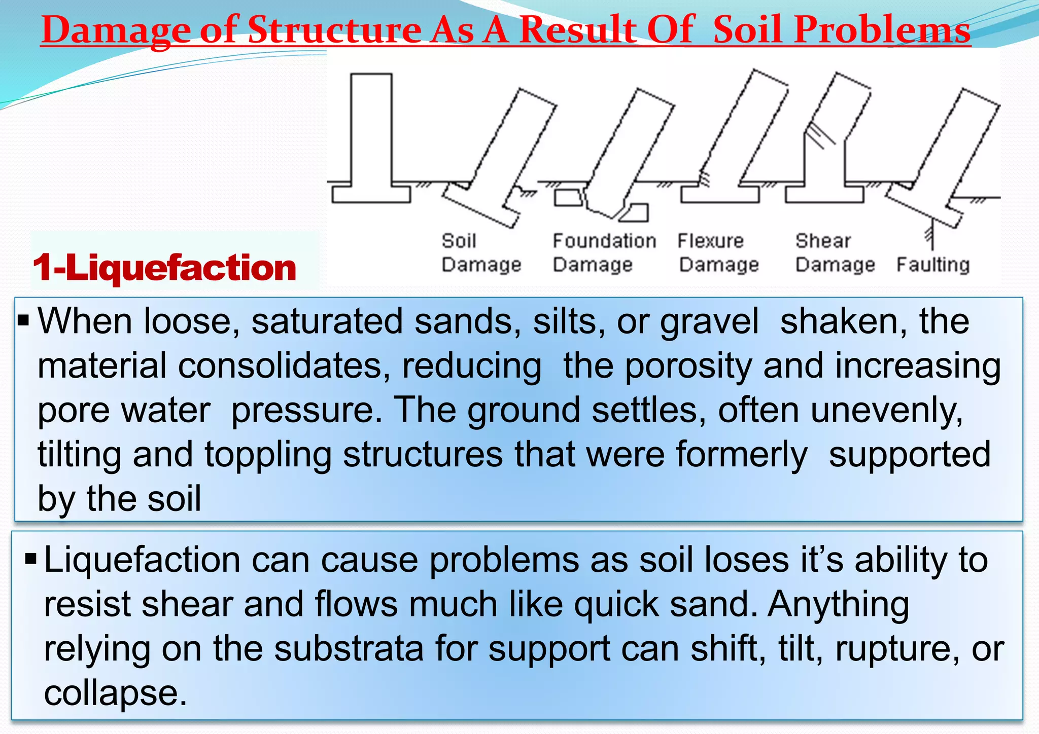
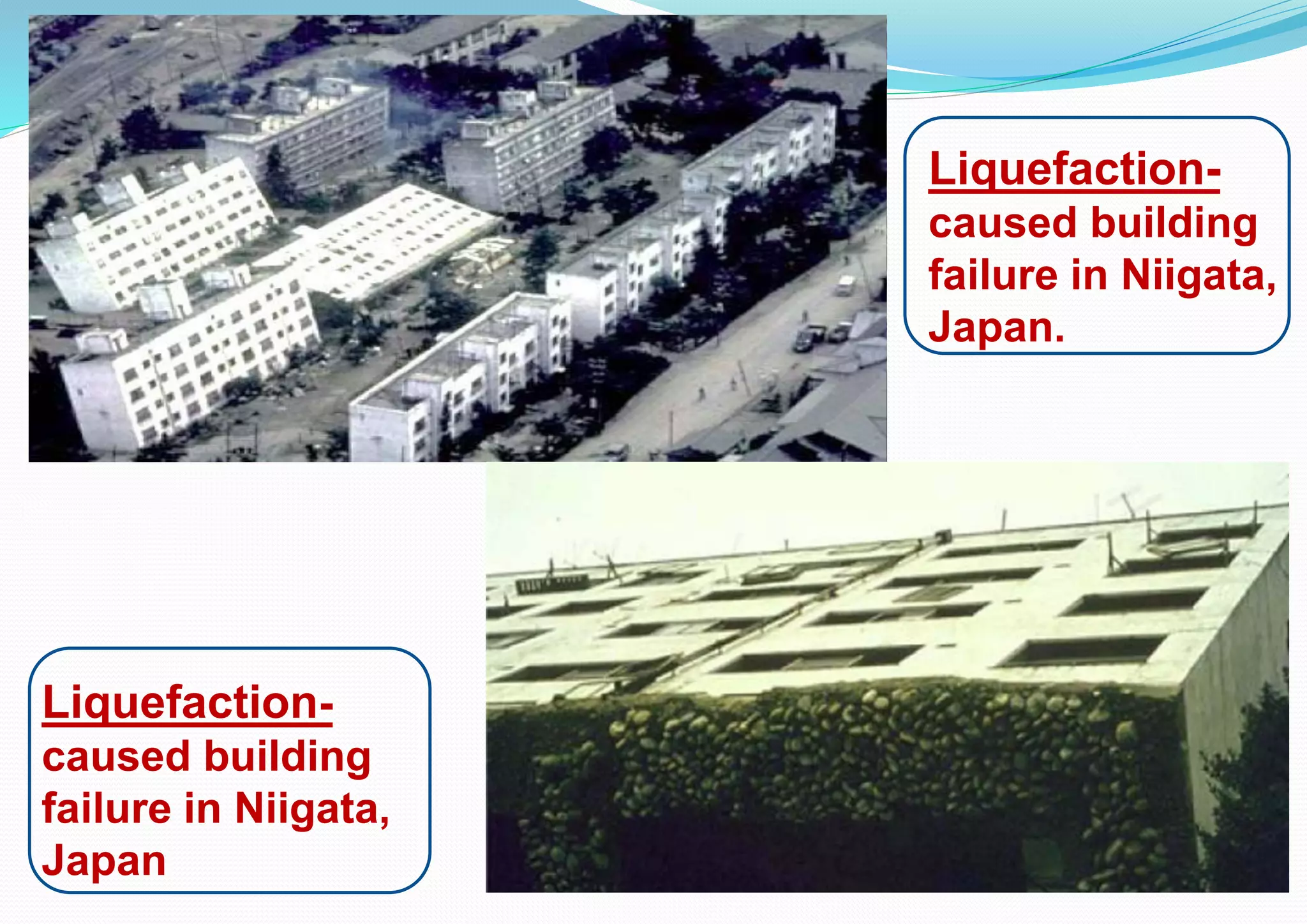
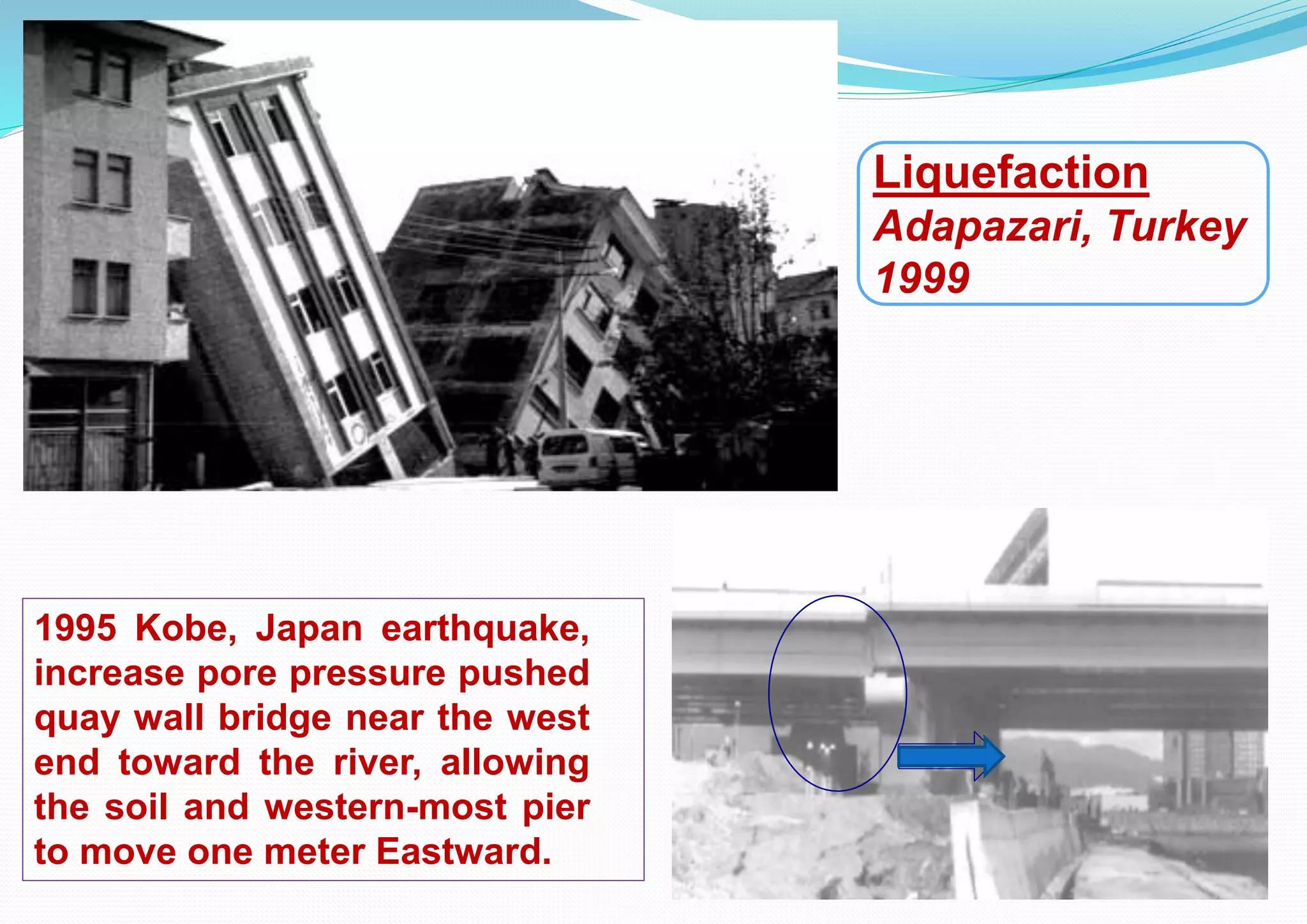
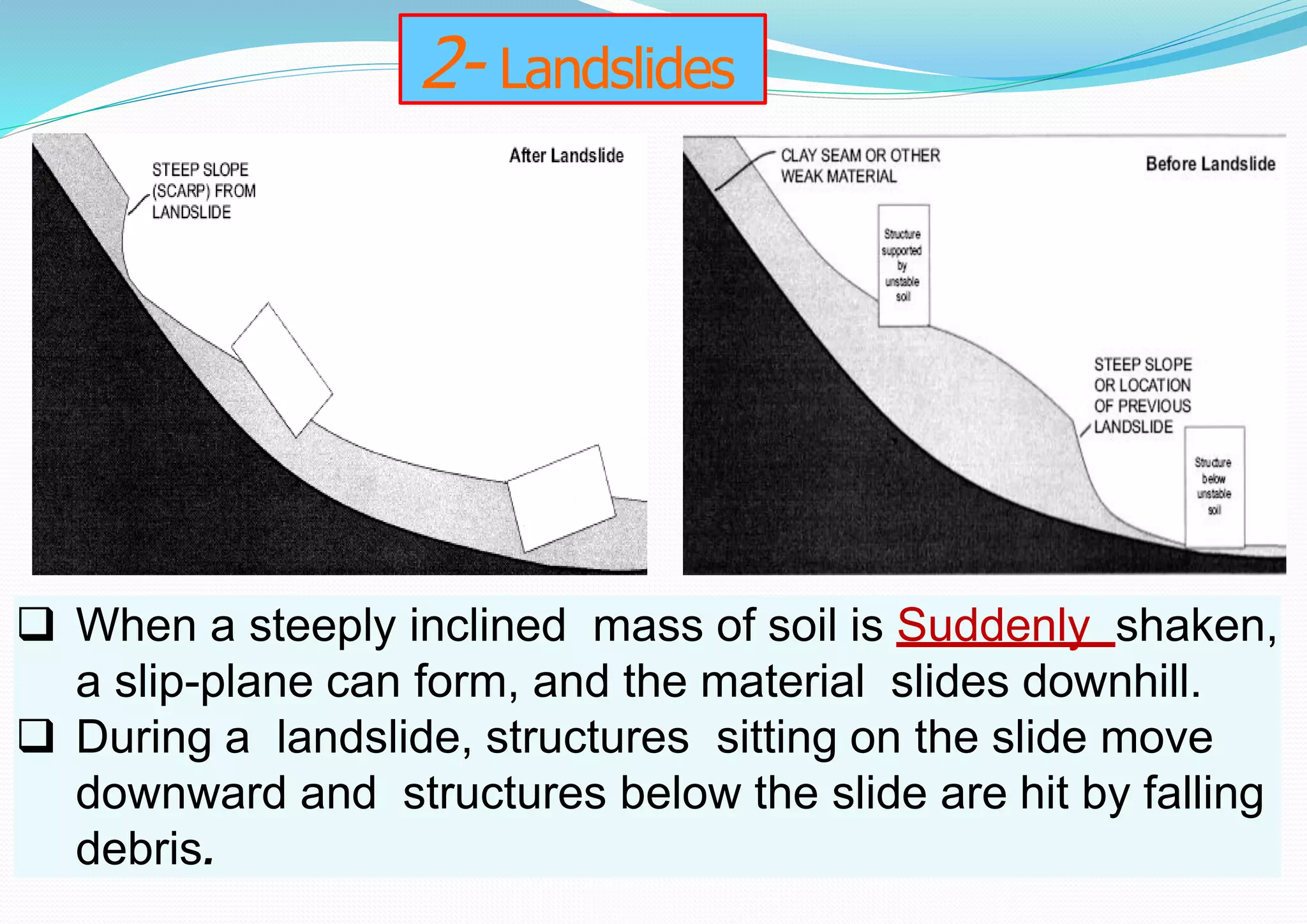
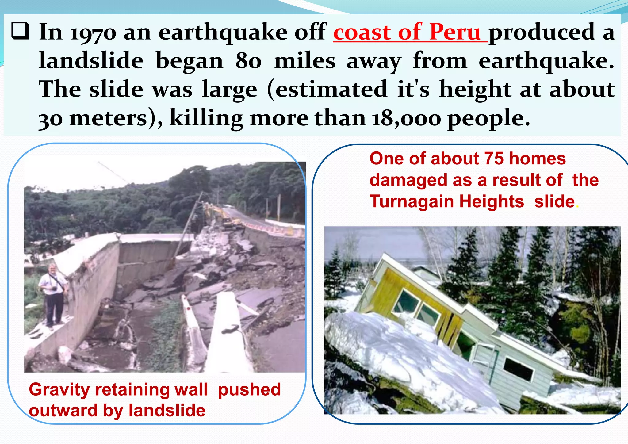
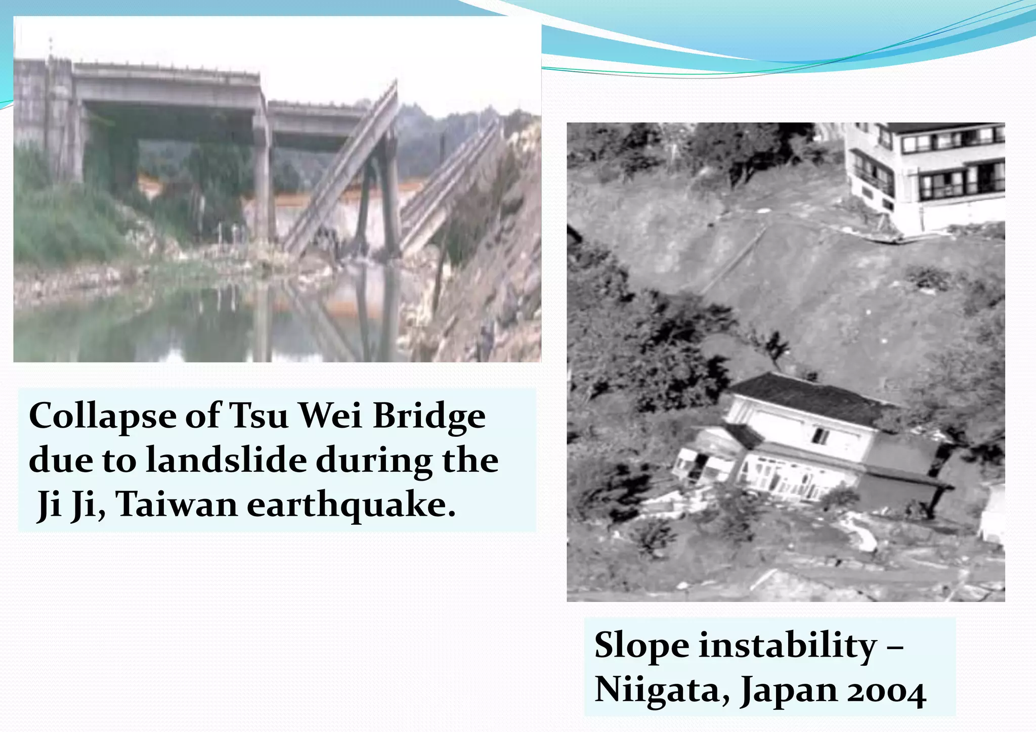
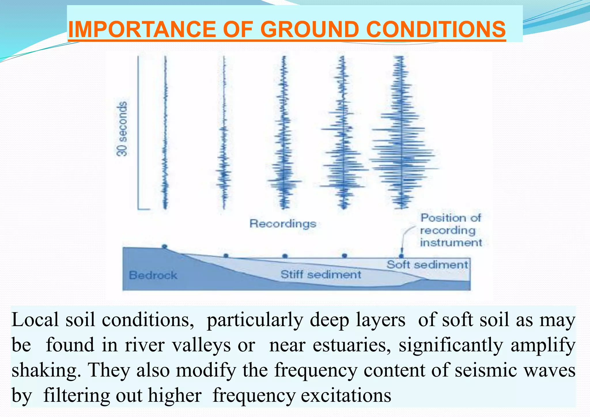
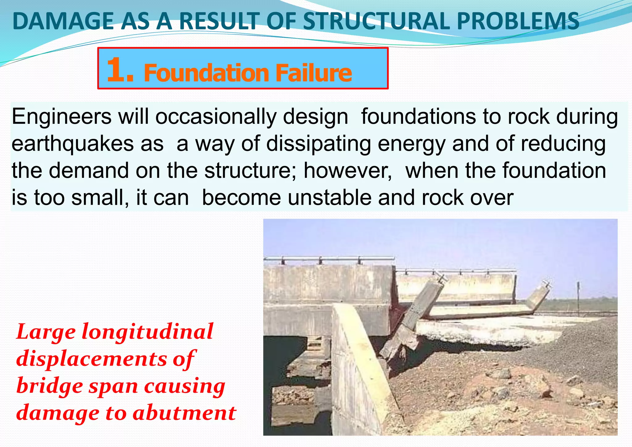
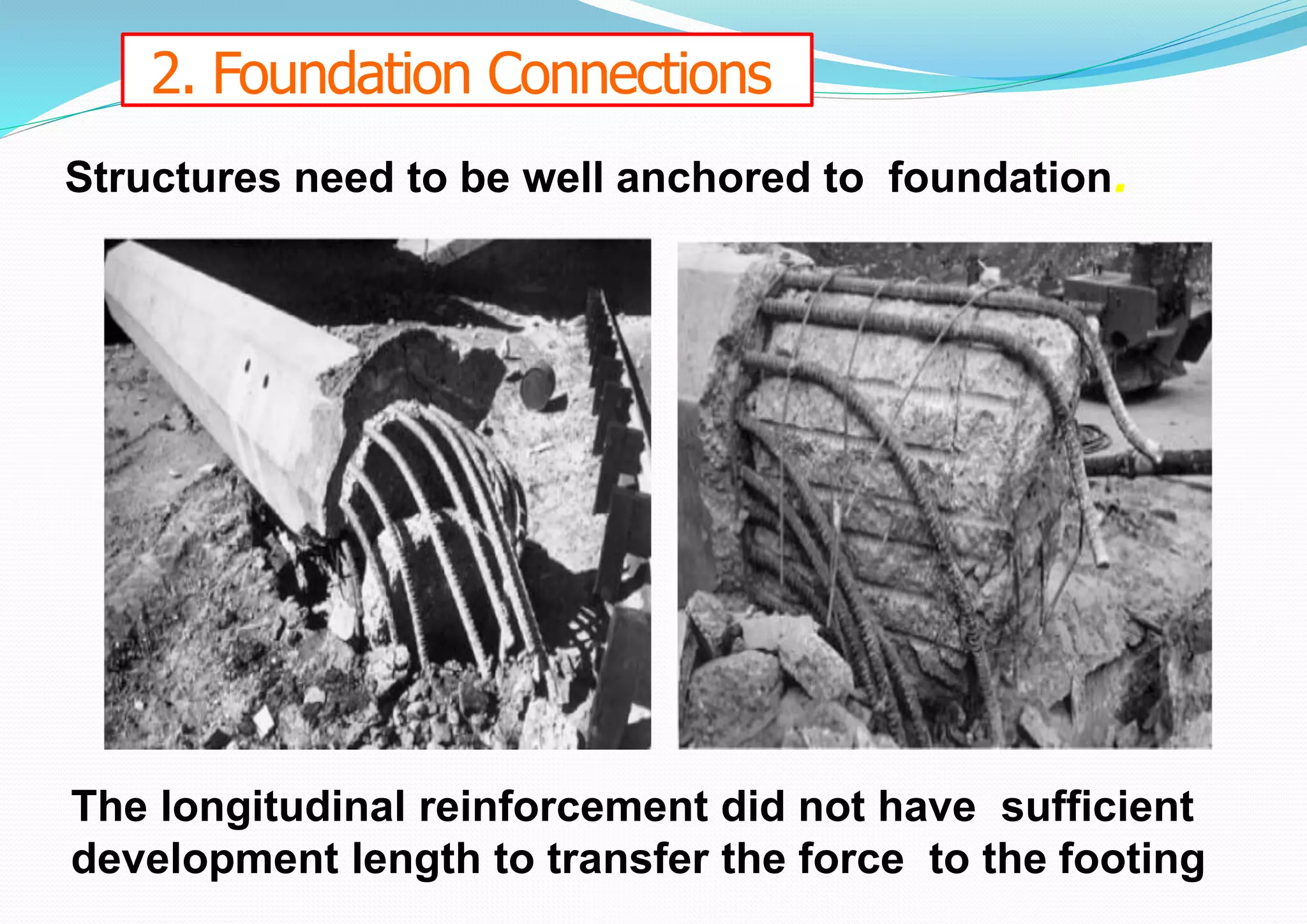

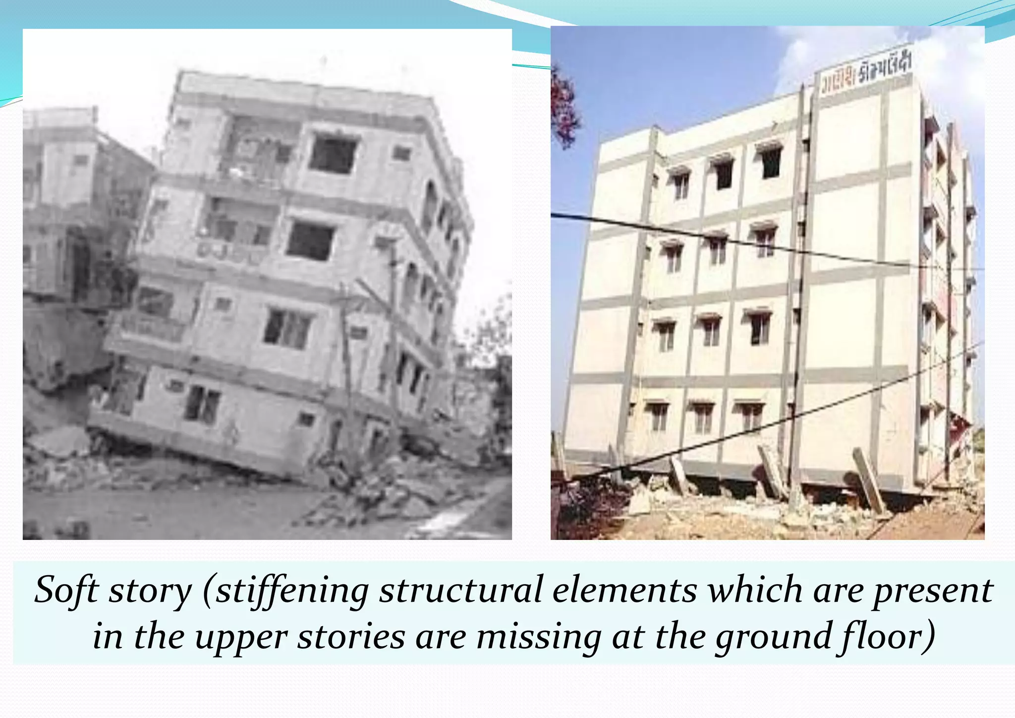
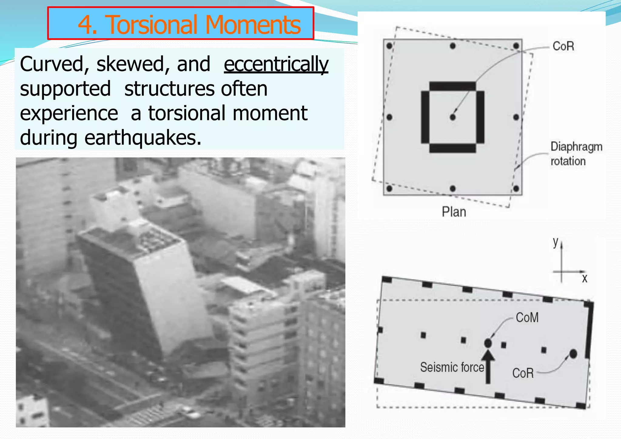
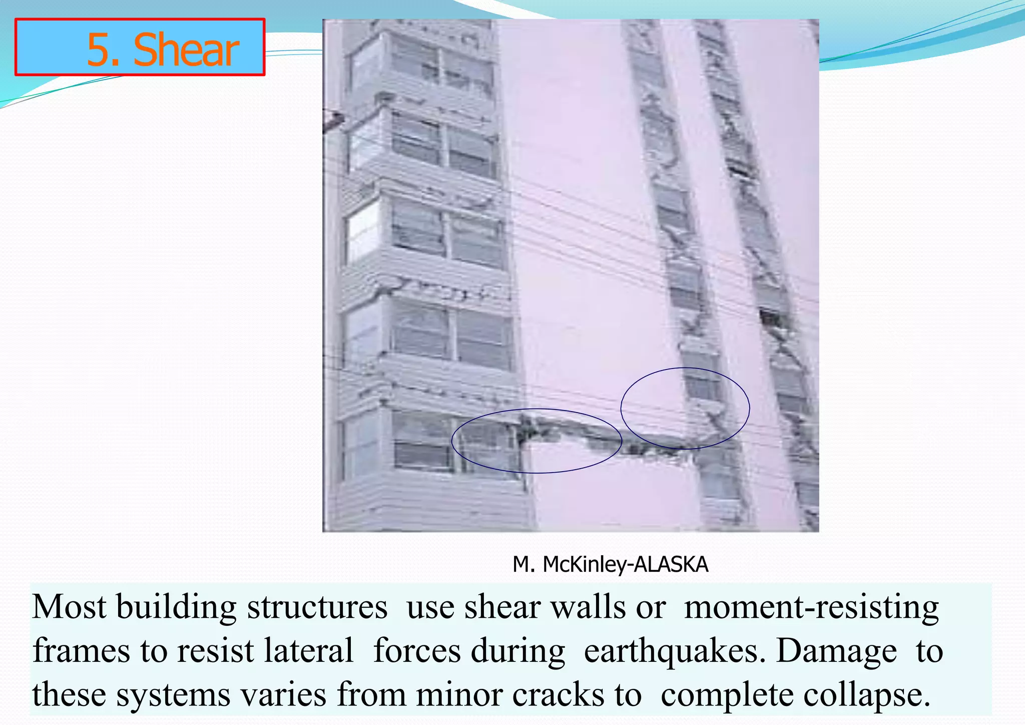
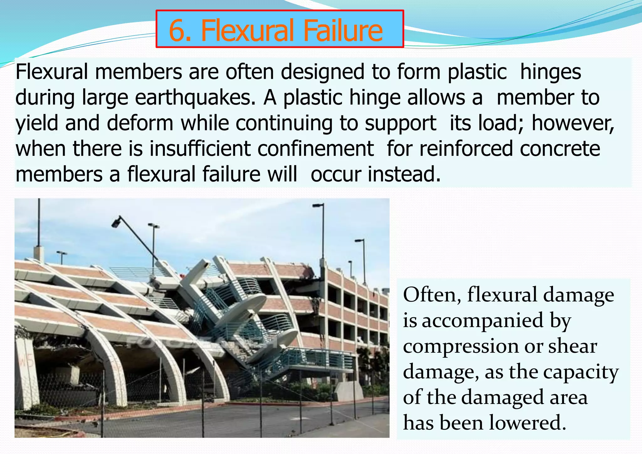
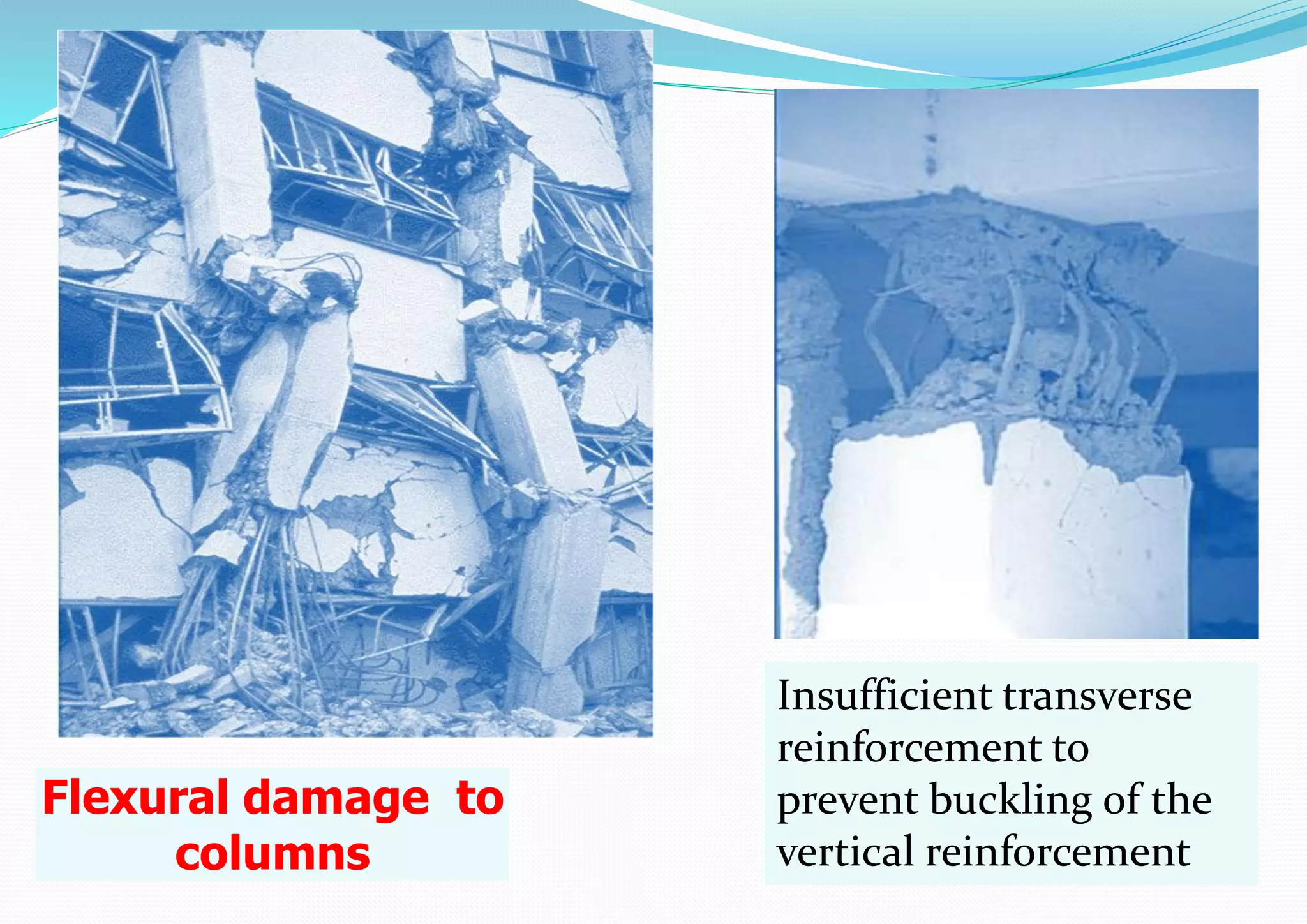
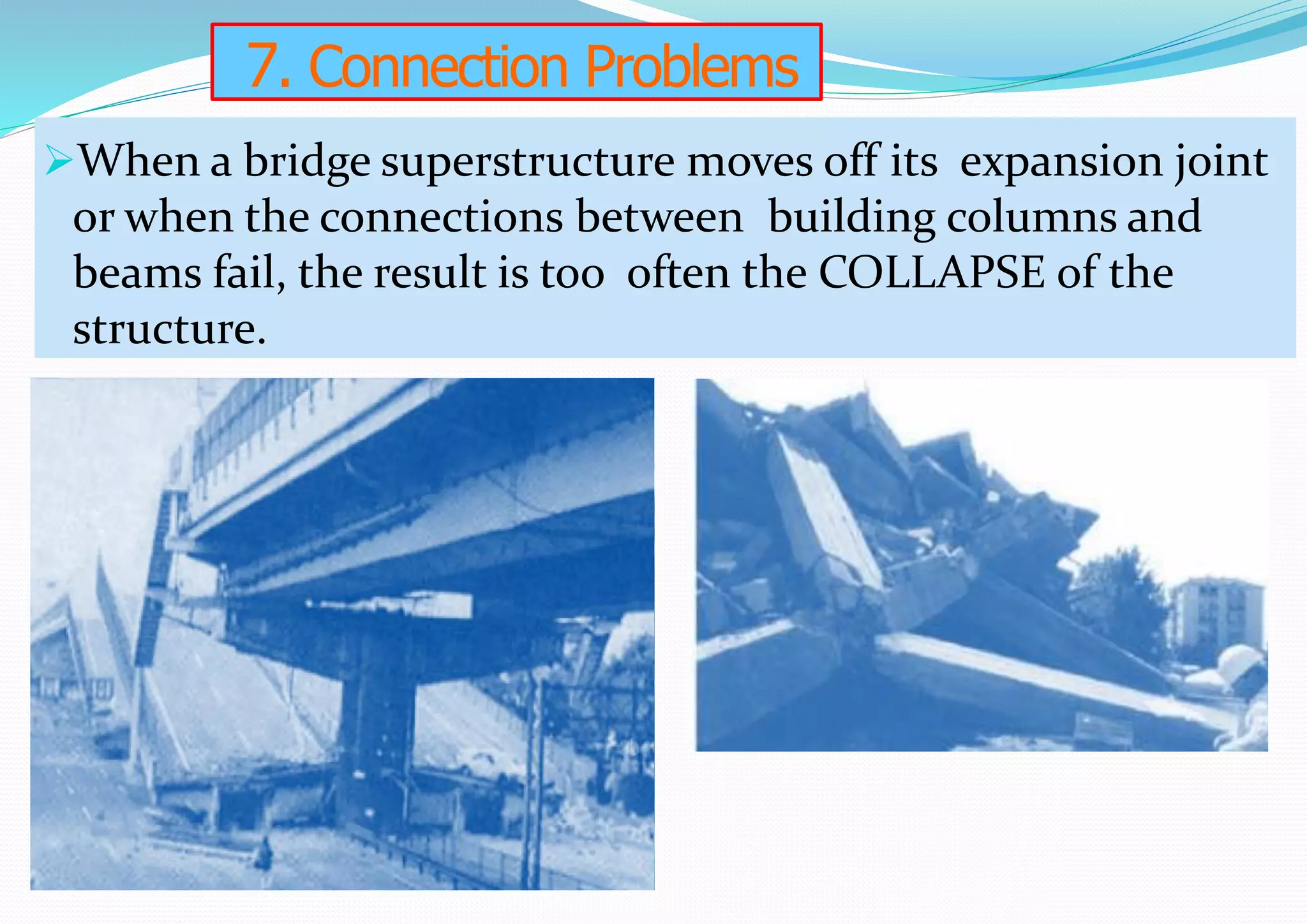
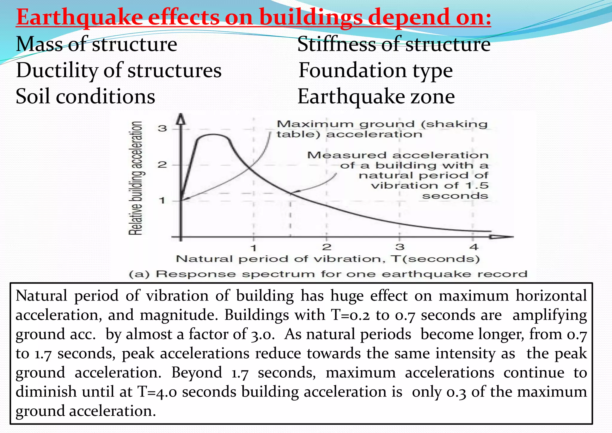


The document discusses the effects of liquefaction and landslides on structures during earthquakes, highlighting how soil conditions can lead to significant damage if a structure's foundation is not adequately designed. It outlines various structural failures, including foundation failures, soft stories, and torsional moments, stressing the importance of anchoring and design considerations during seismic events. The text also emphasizes the role of building characteristics, soil conditions, and analysis methods in determining a building's response to seismic forces.