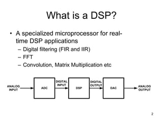
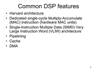
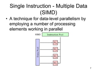
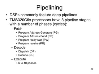
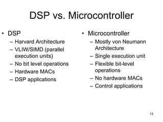
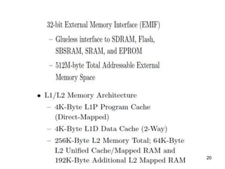
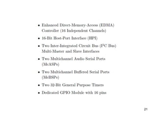
Introduction to Digital Signal
Processors (DSPs)
2
What is a DSP?
• A specialized microprocessor for real-
time DSP applications
– Digital filtering (FIR and IIR)
– FFT
– Convolution, Matrix Multiplication etc
ADC DAC
DSP
ANALOG
INPUT
ANALOG
OUTPUT
DIGITAL
INPUT
DIGITAL
OUTPUT
3
Hardware used in DSP
ASIC FPGA GPP DSP
Performance Very High High Medium Medium High
Flexibility Very low High High High
Power
consumption
Very low low Medium Low Medium
Development
Time
Long Medium Short Short
4
Common DSP features
• Harvard architecture
• Dedicated single-cycle Multiply-Accumulate
(MAC) instruction (hardware MAC units)
• Single-Instruction Multiple Data (SIMD) Very
Large Instruction Word (VLIW) architecture
• Pipelining
• Cache
• DMA
5
Harvard Architecture
• Physically separate
memories and paths
for instruction and
data
DATA
MEMORY
PROGRAM
MEMORY
CPU
6
Single-Cycle MAC unit
Multiplier
Adder
Register
a x
i i
a x
i i
a x
i-1 i-1
a x
i i a x
i-1 i-1
+
Σ(a x )
i i
i=0
n
Can compute a sum of n-
products in n cycles
7
Single Instruction - Multiple Data
(SIMD)
• A technique for data-level parallelism by
employing a number of processing
elements working in parallel
8
Very Long Instruction Word (VLIW)
• A technique for
instruction-level
parallelism by executing
instructions without
dependencies (known at
compile-time) in parallel
• Example of a single
VLIW instruction:
F=a+b; c=e/g; d=x&y; w=z*h;
VLIW instruction F=a+b c=e/g d=x&y w=z*h
PU
PU
PU
PU
a
b
F
c
d
w
e
g
x
y
z
h
ACOE343 - Embedded Real-Time Processor Systems -
Frederick University
9
CISC vs. RISC vs. VLIW
10
Pipelining
• DSPs commonly feature deep pipelines
• TMS320C6x processors have 3 pipeline stages
with a number of phases (cycles):
– Fetch
• Program Address Generate (PG)
• Program Address Send (PS)
• Program ready wait (PW)
• Program receive (PR)
– Decode
• Dispatch (DP)
• Decode (DC)
– Execute
• 6 to 10 phases
11
Direct Memory Access (DMA)
• The feature that allows peripherals to access
main memory without the intervention of the
CPU
• Typically, the CPU initiates DMA transfer, does
other operations while the transfer is in
progress, and receives an interrupt from the
DMA controller once the operation is complete.
• Can create cache coherency problems (the data
in the cache may be different from the data in
the external memory after DMA)
• Requires a DMA controller
12
Cache memory
• Separate instruction and data L1 caches
(Harvard architecture)
• most systems uses DMA
13
DSP vs. Microcontroller
• DSP
– Harvard Architecture
– VLIW/SIMD (parallel
execution units)
– No bit level operations
– Hardware MACs
– DSP applications
• Microcontroller
– Mostly von Neumann
Architecture
– Single execution unit
– Flexible bit-level
operations
– No hardware MACs
– Control applications
14
The TMS320C6713’s high performance CPU and rich peripheral
set are tailored for multichannel audio applications such as
broadcast and recording mixing,
home and large venue audio decoders,
and multi-zone audio distribution.
The TMS320C6713 device is
based on the high-performance advanced VelociTI very-long-
instruction-word (VLIW)architecture developed by Texas
Instruments (TI).
The VelociTI architecture provides ample performance to decode
a variety of existing digital audio formats and the flexibility to add
future formats.
Architecture of TMS320C67xx
TMS320C6713 DSP Starter Kit (DSK) Block Diagram
15
• A TMS320C6713 DSP operating at 225
MHz.
• 16 Mbytes of synchronous DRAM
• 512 Kbytes of non-volatile Flash memory
• (256 Kbytes usable in default conguration)
• 4 user accessible LEDs and DIP switches
• Software board conguration through
• registers implemented in CPLD
16
• JTAG emulation through on-board JTAG
• emulator with USB host interface or
external emulator
17
18
19
20
21

dsp-processor-ppt.ppt

  • 1.
    Introduction to DigitalSignal Processors (DSPs)
  • 2.
    2 What is aDSP? • A specialized microprocessor for real- time DSP applications – Digital filtering (FIR and IIR) – FFT – Convolution, Matrix Multiplication etc ADC DAC DSP ANALOG INPUT ANALOG OUTPUT DIGITAL INPUT DIGITAL OUTPUT
  • 3.
    3 Hardware used inDSP ASIC FPGA GPP DSP Performance Very High High Medium Medium High Flexibility Very low High High High Power consumption Very low low Medium Low Medium Development Time Long Medium Short Short
  • 4.
    4 Common DSP features •Harvard architecture • Dedicated single-cycle Multiply-Accumulate (MAC) instruction (hardware MAC units) • Single-Instruction Multiple Data (SIMD) Very Large Instruction Word (VLIW) architecture • Pipelining • Cache • DMA
  • 5.
    5 Harvard Architecture • Physicallyseparate memories and paths for instruction and data DATA MEMORY PROGRAM MEMORY CPU
  • 6.
    6 Single-Cycle MAC unit Multiplier Adder Register ax i i a x i i a x i-1 i-1 a x i i a x i-1 i-1 + Σ(a x ) i i i=0 n Can compute a sum of n- products in n cycles
  • 7.
    7 Single Instruction -Multiple Data (SIMD) • A technique for data-level parallelism by employing a number of processing elements working in parallel
  • 8.
    8 Very Long InstructionWord (VLIW) • A technique for instruction-level parallelism by executing instructions without dependencies (known at compile-time) in parallel • Example of a single VLIW instruction: F=a+b; c=e/g; d=x&y; w=z*h; VLIW instruction F=a+b c=e/g d=x&y w=z*h PU PU PU PU a b F c d w e g x y z h
  • 9.
    ACOE343 - EmbeddedReal-Time Processor Systems - Frederick University 9 CISC vs. RISC vs. VLIW
  • 10.
    10 Pipelining • DSPs commonlyfeature deep pipelines • TMS320C6x processors have 3 pipeline stages with a number of phases (cycles): – Fetch • Program Address Generate (PG) • Program Address Send (PS) • Program ready wait (PW) • Program receive (PR) – Decode • Dispatch (DP) • Decode (DC) – Execute • 6 to 10 phases
  • 11.
    11 Direct Memory Access(DMA) • The feature that allows peripherals to access main memory without the intervention of the CPU • Typically, the CPU initiates DMA transfer, does other operations while the transfer is in progress, and receives an interrupt from the DMA controller once the operation is complete. • Can create cache coherency problems (the data in the cache may be different from the data in the external memory after DMA) • Requires a DMA controller
  • 12.
    12 Cache memory • Separateinstruction and data L1 caches (Harvard architecture) • most systems uses DMA
  • 13.
    13 DSP vs. Microcontroller •DSP – Harvard Architecture – VLIW/SIMD (parallel execution units) – No bit level operations – Hardware MACs – DSP applications • Microcontroller – Mostly von Neumann Architecture – Single execution unit – Flexible bit-level operations – No hardware MACs – Control applications
  • 14.
    14 The TMS320C6713’s highperformance CPU and rich peripheral set are tailored for multichannel audio applications such as broadcast and recording mixing, home and large venue audio decoders, and multi-zone audio distribution. The TMS320C6713 device is based on the high-performance advanced VelociTI very-long- instruction-word (VLIW)architecture developed by Texas Instruments (TI). The VelociTI architecture provides ample performance to decode a variety of existing digital audio formats and the flexibility to add future formats.
  • 15.
    Architecture of TMS320C67xx TMS320C6713DSP Starter Kit (DSK) Block Diagram 15
  • 16.
    • A TMS320C6713DSP operating at 225 MHz. • 16 Mbytes of synchronous DRAM • 512 Kbytes of non-volatile Flash memory • (256 Kbytes usable in default conguration) • 4 user accessible LEDs and DIP switches • Software board conguration through • registers implemented in CPLD 16
  • 17.
    • JTAG emulationthrough on-board JTAG • emulator with USB host interface or external emulator 17
  • 18.
  • 19.
  • 20.
  • 21.