Module 2
Properties, Composition,and Industrial Application of Engineering
Materials
Metals-
Ferrous: Tool steels and stainless steels.
Non-ferrous /metals: aluminum alloys. Ceramics- Glass, optical fiber glass, cermets.
A metal is a material that is typically hard, shiny and features good electrical
and thermal conductivity.
Metals are generally malleable: they can be hammered or pressed
permanently out of shape without breaking or cracking well as fusible.
Ductile Metals can be either ferrous or non-ferrous.
3.
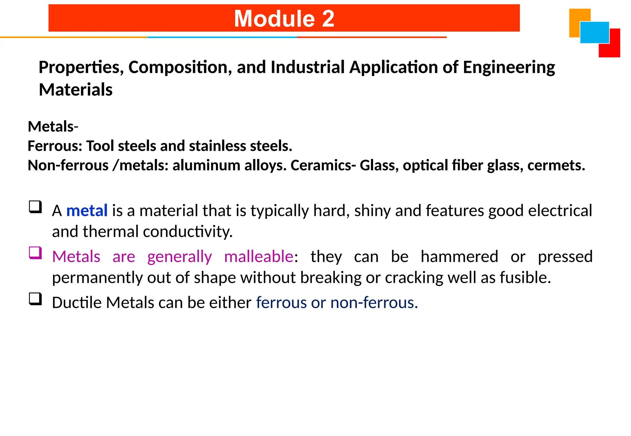
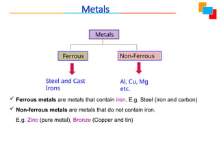
Metals
Metals
Ferrous Non-Ferrous
Steel andCast
Irons
Al, Cu, Mg
etc.
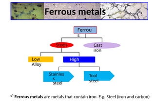
Ferrous metals are metals that contain iron. E.g. Steel (iron and carbon)
Non-ferrous metals are metals that do not contain iron.
E.g. Zinc (pure metal), Bronze (Copper and tin)
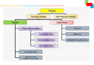
Ferrous Metals -Steels
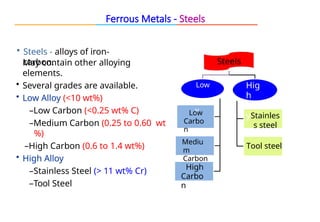
• Steels - alloys of iron-
carbon.
May contain other alloying
elements.
• Several grades are available.
• Low Alloy (<10 wt%)
–Low Carbon (<0.25 wt% C)
–Medium Carbon (0.25 to 0.60 wt
%)
–High Carbon (0.6 to 1.4 wt%)
• High Alloy
–Stainless Steel (> 11 wt% Cr)
–Tool Steel
Steels
Low
allo
y
Low
Carbo
n
Mediu
m
Carbon
High
Carbo
n
Hig
h
allo
yStainles
s steel
Tool steel
6.
Stainless steelis a type of steel that do not get stained and is resistant
to rusting and corrosion.
Stainless steel contain at least 11% Cr. Chromium content ranging from
11% to 25%
Stainless steel will not readily corrode, rust or stain with water unlike
the ordinary steel.
Resistance to attack is due to naturally occurring chromium-rich oxide
film(Cr2O3) formed on the surface of the steel.
The damage is self repairing in the presence of oxygen, and damage by
abrasion, cutting or machining.
Stainless Steels – Composed of ferrite (BCC structure)
Stainless Steel
7.
Properties
Resistant towear
Hard and tough
Exhibits extraordinary corrosion resistance and rust due to formation
of a very thin layer of Cr2O3 on the surface.
Melting Point : 1400°C
Composition
Alloy of iron and carbon with 18% chromium, 8% nickel and 8%
magnesium, 0.03% carbon.
Stainless Steel
8.
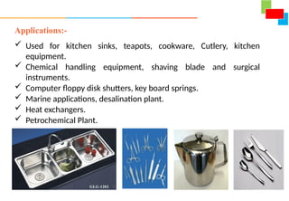
Applications:-
Used forkitchen sinks, teapots, cookware, Cutlery, kitchen
equipment.
Chemical handling equipment, shaving blade and surgical
instruments.
Computer floppy disk shutters, key board springs.
Marine applications, desalination plant.
Heat exchangers.
Petrochemical Plant.
9.
Tool Steel
Toolsteels are special class of steels with carbon content is in the range of
0.8 to 1.2%
Primarily used to make tools in manufacturing process as well as for
machining metals, wood and plastics.
Tool steels are capable of withstanding high loads and remain stable at
elevated temperatures.
It can withstand higher temperatures without loosing its hardness &
toughness.
They are very hard and exhibit good wear and abrasion resistance.
The alloying elements are added to realize this property are tungsten,
vanadium, cobalt, chromium and molybdenum.
A very common example of tool steel is High speed steel
10.
Tool Steel Cont’d……
HighSpeed Steel
Composition
T-Type HSS : Tungsten 12-18%
M-Type HSS : Molybdenum 4-9%
T-Type HSS
18-4-1 HSS: 18% tungsten, 4% chromium, 1% vanadium with a carbon
content of 0.6 - 0.7%.
M-Type HSS
6-6-4-2 HSS : 6% Molybdenum, 6% tungsten, 4% chromium and
2% vanadium, carbon 0.6%
Cobalt high speed steel – increased heat resistance
Molybdenum high speed steel – Mo increases hardness and
wear resistance. Melting Point.1800°C
Also cost effective replacement for tungsten in tool steels.
11.
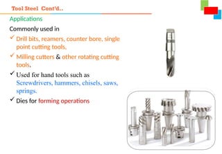
Applications
Commonly used in
Drill bits, reamers, counter bore, single
point cutting tools,
Milling cutters & other rotating cutting
tools.
Used for hand tools such as
Screwdrivers, hammers, chisels, saws,
springs.
Dies for forming operations
Tool Steel Cont’d..
12.
Non Ferrous metals
Non-ferrousmetals are Engineering materials that do not contain iron.
Reasons for preferred are good strength to weight ratio, good resistance
to corrosion, lightweight, high electrical and thermal conductivity, ease of
fabrication.
E.g. Aluminum, Zinc, lead, Bronze (Copper and tin), magnesium, nickel,
chromium, titanium and cobalt.
13.
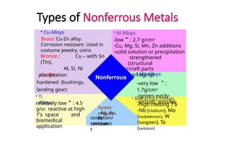
Types of NonferrousMetals
• Al Alloys
-low : 2.7 g/cm3
-Cu, Mg, Si, Mn, Zn additions
-solid solution or precipitation
strengthened
(structural
aircraft parts
& packaging)
• Mg Alloys
-very low :
1.7g/cm3
-ignites easily
-aircraft, missiles
• Refractory metals
-high melting T’s
-Nb (niobium), Mo
(molybdenum), W
(tungsten), Ta
(tantalum)
Noble
metals
- Ag, Au,
Pt
oxidation/
corrosion
resistan
t
• Ti
Alloys
relatively low : 4.5
g/cc reactive at high
T’s space and
biomedical
application
• Cu Alloys
Brass: Cu-Zn alloy.
Corrosion resistant. Used in
costume jewelry, coins
Bronze : Cu – with Sn
(Tin),
Al, Si, Ni
Cu-Be:
precipitation
hardened (bushings,
landing gear)
Nonferrous
14.
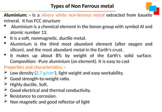
Aluminium: - Isa silvery white non-ferrous metal extracted from bauxite
mineral. It has FCC structure
Aluminium is a chemical element in the boron group with symbol Al and
atomic number 13.
It is a soft, nonmagnetic, ductile metal.
Aluminium is the third most abundant element (after oxygen and
silicon), and the most abundant metal in the Earth's crust.
It makes up about 8% by weight of the Earth's solid surface.
Composition: -Pure aluminium (an element). It is easy to cast
Properties and characteristics: -
Low density (2.7 g/cm3
), light weight and easy workability.
Good strength-to-weight ratio.
Highly ductile, Soft.
Good electrical and thermal conductivity.
Resistance to corrosion.
Non magnetic and good reflector of light
Types of Non Ferrous metal
15.
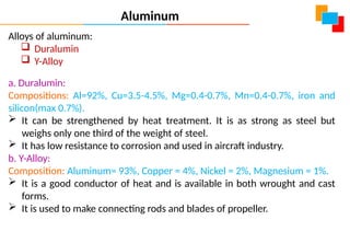
Alloys of aluminum:
Duralumin
Y-Alloy
a. Duralumin:
Compositions: Al=92%, Cu=3.5-4.5%, Mg=0.4-0.7%, Mn=0.4-0.7%, iron and
silicon(max 0.7%).
It can be strengthened by heat treatment. It is as strong as steel but
weighs only one third of the weight of steel.
It has low resistance to corrosion and used in aircraft industry.
b. Y-Alloy:
Composition: Aluminum= 93%, Copper = 4%, Nickel = 2%, Magnesium = 1%.
It is a good conductor of heat and is available in both wrought and cast
forms.
It is used to make connecting rods and blades of propeller.
Aluminum
16.
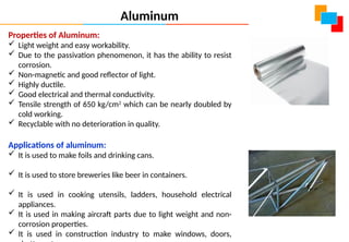
Properties of Aluminum:
Light weight and easy workability.
Due to the passivation phenomenon, it has the ability to resist
corrosion.
Non-magnetic and good reflector of light.
Highly ductile.
Good electrical and thermal conductivity.
Tensile strength of 650 kg/cm2
which can be nearly doubled by
cold working.
Recyclable with no deterioration in quality.
Applications of aluminum:
It is used to make foils and drinking cans.
It is used to store breweries like beer in containers.
It is used in cooking utensils, ladders, household electrical
appliances.
It is used in making aircraft parts due to light weight and non-
corrosion properties.
It is used in construction industry to make windows, doors,
Aluminum
17.
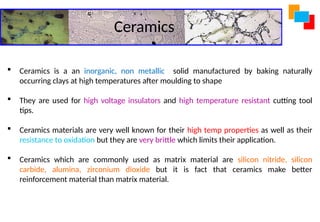
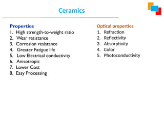
Ceramics
Ceramics isa an inorganic, non metallic solid manufactured by baking naturally
occurring clays at high temperatures after moulding to shape
They are used for high voltage insulators and high temperature resistant cutting tool
tips.
Ceramics materials are very well known for their high temp properties as well as their
resistance to oxidation but they are very brittle which limits their application.
Ceramics which are commonly used as matrix material are silicon nitride, silicon
carbide, alumina, zirconium dioxide but it is fact that ceramics make better
reinforcement material than matrix material.
19
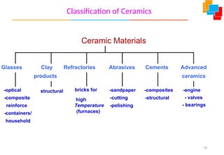
Classification of Ceramics
GlassesClay
products
Refractories Abrasives Cements Advanced
ceramics
-optical
-composite
reinforce
-containers/
household
structural bricks for
high
Temperature
(furnaces)
-sandpaper
-cutting
-polishing
-composites
-structural
-engine
- valves
- bearings
Ceramic Materials
20.
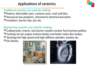
Applications of ceramics
Traditionalceramics are used for making:
Pottery, dish/table ware, sanitary ware, roof wall tiles
Structural clay products, refractories electrical porcelain
Insulators, burner tips, jars etc.
Engineering ceramics are used for making;
Cutting tools, Inserts, Gas burner nozzles nuclear fuel uranium pellets.
Coatings for jet engine turbine blades and boiler tubes disc brakes.
Bearings for high speed and high stiffness spindles, bushes etc.
Die blanks.
21.
Glasses
o Glasses areamorphous or non crystalline ceramic material, usually
silicates containing other oxides like CaO, Na2O, K2O and Al2O3
o Favorable properties such as refractive index, electrical conductivity, etc.
o Crystallization occur during the processing stage in order to give a fine
grained polycrystalline material retain its strength to much higher
temperature.
o Applications in doors, windows, laboratory equipment's, incandescent
bulbs, X ray tubes, fiberglass insulation, windscreen, backlights and
similar such components for automotive and aerospace applications, etc.
22.
Optical Fiber Glass
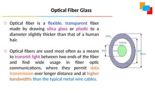
oOptical fiber is a flexible, transparent fiber
made by drawing silica glass or plastic to a
diameter slightly thicker than that of a human
hair.
o Optical fibers are used most often as a means
to transmit light between two ends of the fiber
and find wide usage in fiber optic
communications, where they permit data
transmission over longer distance and at higher
bandwidths than the typical metal wire cables.
23.
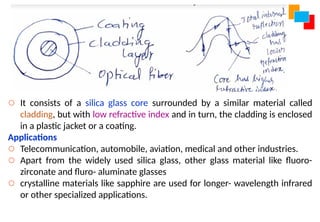
o It consistsof a silica glass core surrounded by a similar material called
cladding, but with low refractive index and in turn, the cladding is enclosed
in a plastic jacket or a coating.
Applications
o Telecommunication, automobile, aviation, medical and other industries.
o Apart from the widely used silica glass, other glass material like fluoro-
zirconate and fluro- aluminate glasses
o crystalline materials like sapphire are used for longer- wavelength infrared
or other specialized applications.
24.
Optical Fiber GlassCont’d...
Advantages
1. Greater band width than metal cables
2. Less susceptible than metal cable to interference
3. Much thinner and lighter than metal wires
4. Data can be transmitted digitally
25.
Cermet getsits name in view of its manufacturing from two
constituents: ceramic (CER) and Metal (MET).
The ceramic material may be either oxide, carbide or boride, while the
metallic material is usually cobalt.
The most widely used cermet consists of tungsten carbide with about
6% cobalt, referred to as cemented carbides. Small amount of nickel are
added to obtain favorable properties.
The ceramic constituent imparts high hardness to the material coupled
with wear, chemical and temperature resistance, while the metallic
constituent imparts ductility to the material that helps to undergo
plastic deformation apart from improving toughness and shock
resistance.
Apart from tungsten carbide, titanium carbide can be combined with
cobalt and nickel to form cermet.
Cermets
26.
Cermets Cont’d…
Applications
Cermetsare mainly used in the fabrication of cutting tools and
components of airplane jet engines and space rockets
Manufacturing of resistors, especially potentiometers, capacitors, and
other electronic components which experience high temperatures during
their service life.
Cermets are also used as insulators and in dentistry as a material for
fillings and prostheses(Artificial substitute).
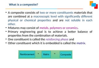
• A compositeconsists of two or more constituents materials that
are combined at a macroscopic level with significantly different
physical or chemical properties and are not soluble in each
other.
• Mixtures may consist of metals, polymers or ceramics.
• Primary engineering goal is to achieve a better balance of
properties from the combination of materials.
• One constituent is called the reinforcing phase and
• Other constituent which it is embedded is called the matrix.
What is a composite?
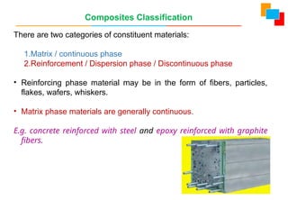
There are twocategories of constituent materials:
1.Matrix / continuous phase
2.Reinforcement / Dispersion phase / Discontinuous phase
• Reinforcing phase material may be in the form of fibers, particles,
flakes, wafers, whiskers.
• Matrix phase materials are generally continuous.
E.g. concrete reinforced with steel and epoxy reinforced with graphite
fibers.
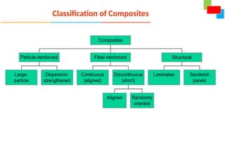
Composites Classification
31.
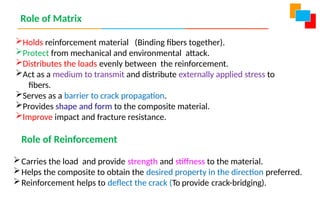
Role of Matrix
Holdsreinforcement material (Binding fibers together).
Protect from mechanical and environmental attack.
Distributes the loads evenly between the reinforcement.
Act as a medium to transmit and distribute externally applied stress to
fibers.
Serves as a barrier to crack propagation.
Provides shape and form to the composite material.
Improve impact and fracture resistance.
Role of Reinforcement
Carries the load and provide strength and stiffness to the material.
Helps the composite to obtain the desired property in the direction preferred.
Reinforcement helps to deflect the crack (To provide crack-bridging).
32.
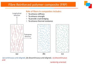
(a) continuous andaligned, (b) discontinuous and aligned, (c) discontinuous
and
randomly oriented
Fibre Reinforced polymer composite (FRP)
Role of fibers in composites includes:
o To enhance stiffness
o To enhance strength
o To provide crack-bridging
o To enhance thermal resistance
33.
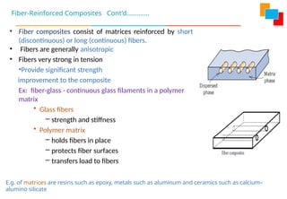
Fiber-Reinforced Composites Cont’d………….
•Fiber composites consist of matrices reinforced by short
(discontinuous) or long (continuous) fibers.
• Fibers are generally anisotropic
• Fibers very strong in tension
•Provide significant strength
improvement to the composite
Ex: fiber-glass - continuous glass filaments in a polymer
matrix
• Glass fibers
– strength and stiffness
• Polymer matrix
– holds fibers in place
– protects fiber surfaces
– transfers load to fibers
E.g. of matrices are resins such as epoxy, metals such as aluminum and ceramics such as calcium–
alumino silicate
34.
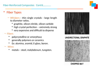
• Fiber Types
–Whiskers - thin single crystals - large length
to diameter ratios.
• graphite, silicon nitride, silicon carbide
• high crystal perfection – extremely strong
• very expensive and difficult to disperse
– Fibers
• polycrystalline or amorphous
• generally polymers or ceramics
• Ex: alumina, aramid, E-glass, boron.
– Wires
• metals – steel, molybdenum, tungsten.
Fiber-Reinforced Composites Cont’d………….
35.
Metal Matrix Composite(MMC)
Metal matrix composites, at present though generating a wide
interest in research fraternity, are not as widely in use as their
plastic counterparts.
Titanium, Aluminium and Magnesium are the popular matrix
metals.
Fibers are small sized particles made from metallic or ceramic
materials
High strength, fracture toughness and stiffness.
Low coefficient of thermal expansion
High melting point,
High expensive manufacturing
They can withstand elevated temperature in corrosive
environment than polymer composites.
The strength-to-weight ratios of resulting composites can be
higher than most alloys.
36.
Uses of MMC:
Pistons
Pushrods, Brake components
Turbine engine components like fan blades
Actuators pistons, connecting links
Shafts
Electrical and electronic components
Matrix – Ductile Metal (usually alloys of aluminum, magnesium,
titanium, and copper)
Fibre - Carbon, Silicon Carbide, Boron, Aluminum oxide, etc.
Advantages over PMC includes:
Higher operating temperatures.
Non-flammability.
Greater resistance to degradation by organic fluids.
Demerit: MMCs are costlier than PMCs
37.
Applications Of CompositesIn Aircrafts
Airframe of an aircraft
Main landing gear door
Helicopter rotor blades
Aircraft propeller blades
Aircraft seats.
Instrument panels.
CFRP (carbon fiber-reinforced polymer) is used in wing and nose.
Used to deflect radar waves and also to absorb them.
The new Boeing 787 Dreamliner aircraft uses almost 50 % of the
parts made of composite materials, thus reducing its overall
weight by 12 %.
38.
Smart Materials
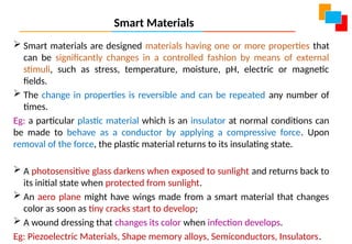
Smartmaterials are designed materials having one or more properties that
can be significantly changes in a controlled fashion by means of external
stimuli, such as stress, temperature, moisture, pH, electric or magnetic
fields.
The change in properties is reversible and can be repeated any number of
times.
Eg: a particular plastic material which is an insulator at normal conditions can
be made to behave as a conductor by applying a compressive force. Upon
removal of the force, the plastic material returns to its insulating state.
A photosensitive glass darkens when exposed to sunlight and returns back to
its initial state when protected from sunlight.
An aero plane might have wings made from a smart material that changes
color as soon as tiny cracks start to develop;
A wound dressing that changes its color when infection develops.
Eg: Piezoelectric Materials, Shape memory alloys, Semiconductors, Insulators.
39.
Piezoelectric materialsare those materials that produce an electric current
when they are subjected to mechanical stress.
piezoelectric materials have two unique properties which are interrelated.
When a piezoelectric material is deformed by applying stress, it gives off a
small electrical discharge.
Alternately, when an electrical current is passed through a piezoelectric
material it experiences a significant deformation.
Because of this property, piezoelectric materials are widely used as sensor in
different environments.
Common piezoelectric materials
Quartz, lead zirconium titanate (PZT), Barium titanate, lead zirconate titanate,
Potassium nibate etc. and polymer material like Polyvinylidene fluoride,
tourmaline.
Piezoelectric Materials
40.
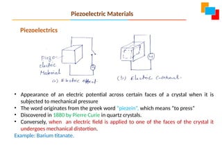
Piezoelectrics
• Appearance ofan electric potential across certain faces of a crystal when it is
subjected to mechanical pressure
• The word originates from the greek word “piezein”, which means “to press”
• Discovered in 1880 by Pierre Curie in quartz crystals.
• Conversely, when an electric field is applied to one of the faces of the crystal it
undergoes mechanical distortion.
Example: Barium titanate.
Piezoelectric Materials
41.
Applications of Piezoelectricmaterials
In automotive industries Piezoelectric materials are used as air bag
sensor, air flow sensor, audible alarms, keyless door entry, seat
belt buzzers etc.
In computers Piezoelectric materials are used as actuators for disc
drives, dot matrix/ inkjet printing heads etc.
In medical field Piezoelectric materials are used in ultrasonic
imaging, ultrasonic cataract removal device etc.
In military Piezoelectric materials are used in depth sounders,
guidance systems, sonar etc.,
In manufacturing system Piezoelectric materials are used in
ultrasonic cleaning, ultrasonic welding, etc
Piezoelectric materials are also used as depth finder, humidifiers,
jewellery cleaners, musical instruments, speakers, cigarette
lighters etc..
42.
Shape Memory Alloys
INTRODUCTION
Shapememory alloy is an alloy.
SMA a is one the type of smart materials.
Shape Memory Alloys are materials that “remember” their original
shape.
If deformed, they recover their original shape upon heating.
They can take large stresses without undergoing permanent
deformation.
They can be formed into various shapes like bars, wires, plates and
rings thus serving various functions.
43.
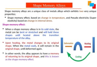
Shape memory effect:
When a shape memory alloys is in its cold state, the
metal can be bent or stretched and will hold those
shapes until heated above the transition
temperature of the alloy.
Upon heating, the metal changes to its original
shape. When the metal cools, it will remain in the
original shape, until deformed again.
In other words, the alloy appears to have a memory
of returning to its original shape, and this is known
as the shape memory effect.
Shape Memory Alloys
Shape memory alloys are a unique class of metals alloys which exhibits two very unique
properties:
Shape memory effect, based on change in temperature, and Pseudo electricity (Super
elasticity) based on change in internal stress.
44.
Pseudo elasticity orSuper elasticity:
Shape memory alloys exhibits super elasticity ie a mechanical type of
shape memory. In this case, a force induces considerable deformation
in the alloy material, but when the force is removed, the material
automatically recovers its original shape without the need for heating.
Pseudo elasticity effect is observed when alloys are strained just above
their transition temperature.
Eg: Alloys like Cu-Zn-Al, Cu-Ni-Al, Cu-Be-Al, Fe-Mn-Si, Ni-Al, Ti-Pd, Au-Cd,
Cu-Sn etc. Ni-Ti (Nickel- Titanium) alloy, referred as Nitinol is widely
used for commercial applications.
Shape Memory Alloys
45.
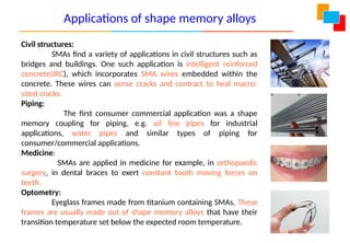
Civil structures:
SMAs finda variety of applications in civil structures such as
bridges and buildings. One such application is intelligent reinforced
concrete(IRC), which incorporates SMA wires embedded within the
concrete. These wires can sense cracks and contract to heal macro-
sized cracks.
Piping:
The first consumer commercial application was a shape
memory coupling for piping, e.g. oil line pipes for industrial
applications, water pipes and similar types of piping for
consumer/commercial applications.
Medicine:
SMAs are applied in medicine for example, in orthopaedic
surgery, in dental braces to exert constant tooth moving forces on
teeth.
Optometry:
Eyeglass frames made from titanium containing SMAs. These
frames are usually made out of shape memory alloys that have their
transition temperature set below the expected room temperature.
Applications of shape memory alloys
46.
• Semiconductors arematerials having electrical conductivity between that of
conductors and insulators.
• Semiconductors can be pure elements such as silicon or germanium or compounds
such as gallium arsenide.
• The conducting properties of semiconductors can be altered by the inclusion of
impurities called doping, in to the crystal structure.
• Doping generally increases the number charge carriers within the crystal causing
electricity to pass through them easily.
• Since the electrical properties of a semiconductor material can be modified by
doping, or by the application of electrical fields or light, devices made from
semiconductors can be used for amplification, switching and energy conversion.
• Today’s electronic technology involves the use of semiconductors for making
integrated circuits (IC), which are found in laptops, scanners, cell phones, medical
diagnostic equipment's, refrigerators, air conditioners, programmable machines and
robots, etc.
Semiconductors
47.
• An insulatoris a material which is a poor conductor of heat and electricity.
Wood, plastic, ceramic materials like glass, porcelain etc., rubber like polymers
and plastics are common examples of insulators.
• Insulators possess high resistivity; the charges do not flow freely as in the case
of conductors and semiconductors. Insulators thus work as protectors.
• They are used in equipments to support and separate electrical conductors
without allowing current to flow through themselves.
• Electric wires and cables are often coated with insulated materials; printed
circuit boards are made from epoxy plastic and fiberglass.
• power distribution or transmission lines make use of glass, porcelain or
composite polymer materials to protect living beings from the dangerous
effects of electricity.
• Apart from preventing the passage of heat and electricity, an insulator can also
prevent the passage of sound from one location to another. Fiber glass, plastic
foam, mineral wool, cellulose etc., are generally used for the purpose.
Insulators
48.
Soldering, Brazing andWelding: Definitions. Classification and methods of soldering,
brazing, and welding. Brief description of arc welding, Oxy-acetylene welding,
Introduction to TIG welding and MIG welding.
There are various processes by which two or more parts can be joined
together. The joints obtained by these processes may be temporary or
permanent.
Joints obtained by processes like brazing, soldering, bolts and nuts, studs
and nuts, screws etc., are temporary in nature. These joints can be
separated without damage them.
Whereas processes like welding, riveting etc., produce permanent joints.
These parts can be separated by breaking them.
Metal Joining Processes
49.
Soldering
Soldering isa method of uniting two thin metal pieces using a dissimilar
metal or an alloy with the application of heat.
The alloy of lead and tin is called soft solder, is used in varying proposition
for sheet metal work, plumbing work and electrical junctions.
The melting temp of the soft solder will be between 150° to 350° C.
Clean the joint surfaces to prevent the oxidation, a suitable flux is used
while soldering. Zinc chloride, Rosin or borax is the flux that is commonly
used in soft soldering.
A soldering iron is used to apply the heat produced from the electrical
source.
An alloy of copper, tin, and silver known as hard solder is used for
stronger joint.
The soldering temp of hard solder ranges from 600 ° to 900 ° C.
50.
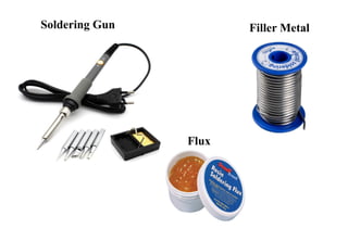
Types of solder(filler metal)
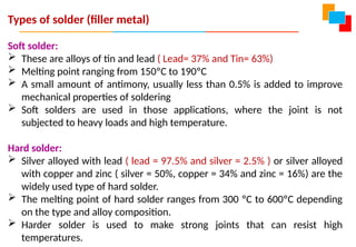
Soft solder:
These are alloys of tin and lead ( Lead= 37% and Tin= 63%)
Melting point ranging from 150ºC to 190ºC
A small amount of antimony, usually less than 0.5% is added to improve
mechanical properties of soldering
Soft solders are used in those applications, where the joint is not
subjected to heavy loads and high temperature.
Hard solder:
Silver alloyed with lead ( lead = 97.5% and silver = 2.5% ) or silver alloyed
with copper and zinc ( silver = 50%, copper = 34% and zinc = 16%) are the
widely used type of hard solder.
The melting point of hard solder ranges from 300 ºC to 600ºC depending
on the type and alloy composition.
Harder solder is used to make strong joints that can resist high
temperatures.
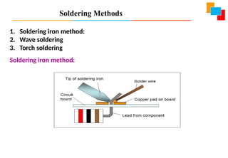
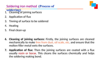
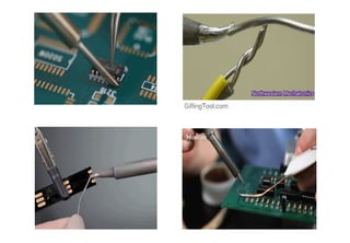
Soldering iron method(Process of
soldering)
1. Cleaning of joining surfaces
2. Application of flux
3. Tinning of surface to be soldered
4. Heating
5. Final clean-up
6. Cleaning of joining surfaces: Firstly, the joining surfaces are cleaned
mechanically to make free from dust, oil scale, etc. and ensure that the
molten filler metal wets the surfaces.
7. Application of flux: Then the joining surfaces are coated with a flux
usually rosin or borax. This cleans the surfaces chemically and helps
the soldering making bond.
53.
3. Tinning ofsurface to be soldered: Before carrying out the soldering
operation, the soldering iron must be tinned.
This is to remove a thin film of oxide that forms on the copper bit, which
in turns does not allow the job to be heated and thus it becomes difficult
to solder.
In tinning the copper bit is heated and then rubbed with a file to clean it
properly and then rotating with solder using resin.
This causes the formation of a thin film of solder over the copper bit. This
whole process is called tinning.
4. Heating: the soldering iron is then heated and flowing molten filler
metals fills the joints interface. Allow the soldered area to cool and then
solidify thus making the joint.
5. Final clean-up: after completing the soldering and joints are formed,
clean it with steel wool or solvent to remove left over flux. After this
clean the soldering iron using a damp sponge.
Soldering iron method (Process of
soldering)
54.
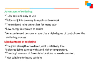
Advantages of soldering:
Low cost and easy to use
Soldered joints are easy to repair or do rework
The soldered joint cannot last for many year
Low energy is required to solder
An experienced person can exercise a high degree of control over the
soldering process
Disadvantages of soldering
The joint strength of soldered joint is relatively low.
Soldered joints cannot withstand higher temperature.
Thorough removal of fluxes is to be done to avoid corrosion.
Not suitable for heavy sections
55.
Applications of soldering
1.Used in assembling electronic components to printed circuit
boards(PCB’s).
2. Making connections between copper pipes in plumbing systems.
3. Joints in sheet metal objects such as food cans, metal container and rain
gutters are made by soldering.
4. The process can also be used as a semi permanent patch for a leak in a
container, or cooking vessel.
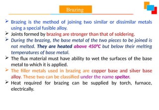
Brazing isthe method of joining two similar or dissimilar metals
using a special fusible alloy.
Joints formed by brazing are stronger than that of soldering.
During the brazing, the base metal of the two pieces to be joined is
not melted. They are heated above 450°C but below their melting
temperatures of base metal.
The flux material must have ability to wet the surfaces of the base
metal to which it is applied.
The filler metals used in brazing are copper base and silver base
alloy. These two can be classified under the name spelter.
Heat required for brazing can be supplied by torch, furnace,
electrically.
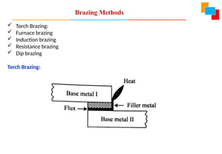
Brazing
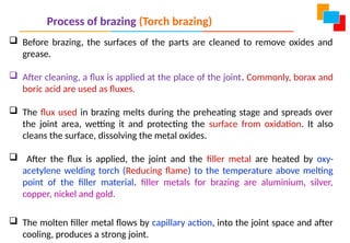
Process of brazing(Torch brazing)
Before brazing, the surfaces of the parts are cleaned to remove oxides and
grease.
After cleaning, a flux is applied at the place of the joint. Commonly, borax and
boric acid are used as fluxes.
The flux used in brazing melts during the preheating stage and spreads over
the joint area, wetting it and protecting the surface from oxidation. It also
cleans the surface, dissolving the metal oxides.
After the flux is applied, the joint and the filler metal are heated by oxy-
acetylene welding torch (Reducing flame) to the temperature above melting
point of the filler material. filler metals for brazing are aluminium, silver,
copper, nickel and gold.
The molten filler metal flows by capillary action, into the joint space and after
cooling, produces a strong joint.
61.
Advantages of Brazing
•It is easy to learn and work.
• It can join virtually any dissimilar metals.
• The bond line (line of joint) is neat aesthetically.
• Brazing may avoid the metallurgical damage to the base metals.
• Less heating is required than for welding.
• Joint strength is good for most of the non- heavy duty applications.
Disadvantages of Brazing
• Joint strength obtained is less compared to welding.
• Safety precautions to be taken are more since it involves handling
chemicals like borax, boric acid etc.
• It is difficult to join large sections with brazing.
• The filler materials are expensive and hence will add up to the brazing
process cost.
62.
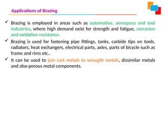
Applications of Brazing
Brazing is employed in areas such as automotive, aerospace and tool
industries, where high demand exist for strength and fatigue, corrosion
and oxidation resistance.
Brazing is used for fastening pipe fittings, tanks, carbide tips on tools,
radiators, heat exchangers, electrical parts, axles, parts of bicycle such as
frame and rims etc..
It can be used to join cast metals to wrought metals, dissimilar metals
and also porous metal components.
63.
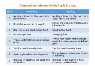
Sl no SolderingBrazing
1 Melting point of the filler material is
below 450 °C
Melting point of the filler material is
about 450 °C and above
2 Dissimilar metals can be joined. Similar and Dissimilar metals can be
joined easily
3 Does not yield a good surface finish Good surface finish
4 Less stronger joint. Stronger joints
5 Typical solder filler metals are alloys
of tin
Typical filler metals for brazing are
aluminium, silver, copper, nickel and
gold
6 The flux used is usually Rosin The flux used is usually Borax
7 Soldering is an Economical process Brazing is not as economical process
as soldering
8
It is used for electrical and electronic
applications.
It is used for production of heat
exchangers and radiators.
Comparison between Soldering & Brazing
64.
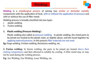
Welding is ametallurgical process of joining two similar or dissimilar metallic
components with the application of heat, with or without the application of pressure and
with or without the use of filler metal.
Welding process is broadly classified into two types
i. plastic welding.
ii. Fusion welding
1. Plastic welding (Pressure Welding) :
Plastic welding also called as pressure welding. In plastic welding, the metal parts to
be joined are heated to the plastic state, or slightly above, and the fused together by
applying external pressure. In this process filler materials are not used.
Eg: Forge welding, Friction welding, Resistance welding, etc.
2. Fusion welding: In fusion welding, the parts to be joined are heated above their
melting temperatures and then allowed to solidify by cooling. A filler metal may or may
not be used during the welding process.
Eg: Arc Welding, Gas Welding, Laser Welding, etc.
Welding
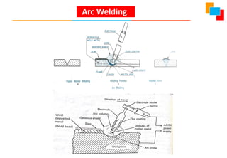
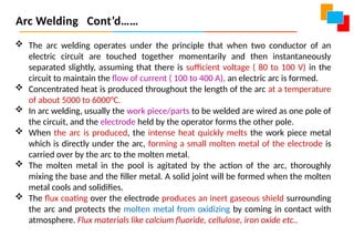
The arcwelding operates under the principle that when two conductor of an
electric circuit are touched together momentarily and then instantaneously
separated slightly, assuming that there is sufficient voltage ( 80 to 100 V) in the
circuit to maintain the flow of current ( 100 to 400 A), an electric arc is formed.
Concentrated heat is produced throughout the length of the arc at a temperature
of about 5000 to 6000°C.
In arc welding, usually the work piece/parts to be welded are wired as one pole of
the circuit, and the electrode held by the operator forms the other pole.
When the arc is produced, the intense heat quickly melts the work piece metal
which is directly under the arc, forming a small molten metal of the electrode is
carried over by the arc to the molten metal.
The molten metal in the pool is agitated by the action of the arc, thoroughly
mixing the base and the filler metal. A solid joint will be formed when the molten
metal cools and solidifies.
The flux coating over the electrode produces an inert gaseous shield surrounding
the arc and protects the molten metal from oxidizing by coming in contact with
atmosphere. Flux materials like calcium fluoride, cellulose, iron oxide etc..
Arc Welding Cont’d……
67.
Advantages Of ArcWelding
1. Strength of the arc welded joints are high.
2. Almost all metals can be arc welded.
3. No need of highly specialized equipment.
4. Cost per unit of welding is comparatively less.
5. It can be widely applied for domestic, industrial and specialized use.
Applications of Arc Welding
Building and bridge construction,
Ship building
Boiler and pressure vessel fabrication
Joining of large pipes and penstock
In almost all repair and maintenance work.
Arc Welding Cont’d……
68.
Gas Welding
Gaswelding is a fusion type welding operations that burn various fuels
mixed with oxygen.
Oxy Fuel Welding employs several types of gases, which is the primary
distinction among the members of this group, Gas mixtures that can be
used are:
1. Oxygen – Acetylene mixture and
2. Oxygen – Hydrogen mixture
As in Arc Welding, Filler metal is sometimes added & the Composition
must be similar to that of the base metal. Filler rod often coated with flux
to clean surfaces and prevent oxidation.
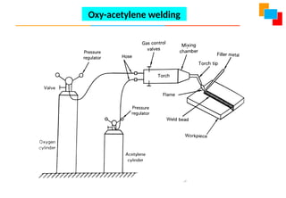
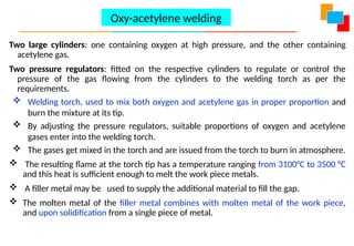
Two large cylinders:one containing oxygen at high pressure, and the other containing
acetylene gas.
Two pressure regulators: fitted on the respective cylinders to regulate or control the
pressure of the gas flowing from the cylinders to the welding torch as per the
requirements.
Welding torch, used to mix both oxygen and acetylene gas in proper proportion and
burn the mixture at its tip.
By adjusting the pressure regulators, suitable proportions of oxygen and acetylene
gases enter into the welding torch.
The gases get mixed in the torch and are issued from the torch to burn in atmosphere.
The resulting flame at the torch tip has a temperature ranging from 3100°C to 3500 °C
and this heat is sufficient enough to melt the work piece metals.
A filler metal may be used to supply the additional material to fill the gap.
The molten metal of the filler metal combines with molten metal of the work piece,
and upon solidification from a single piece of metal.
Oxy-acetylene welding
71.
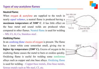
Types of oxy-acetyleneflames
Neutral Flame:
When oxygen & acetylene are supplied to the torch in
nearly equal volumes, a neutral flame is produced having a
maximum temperature of 3100º C. It has little effect on
the base metal and sound welds are produced when
compared to other flames. Neutral flame is used for welding
– MS, CI, Al, Cu, Stainless steel .
Oxidizing Flame:
In an oxidizing flame excess of oxygen is present. The flame
has a inner white cone somewhat small, giving rise to
higher tip temperature (3300º C). Excess of oxygen in the
oxidizing flame causes the metal to burn or oxidize quickly.
Oxidizing flame is useful for welding some nonferrous
alloys such as copper and zinc base alloys. Oxidizing flame
is used for welding – Copper-base metals, Zinc-base metals,
ferrous metals such as Mn steel, CI, etc.
72.
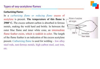
Types of oxy-acetyleneflames
Carburizing Flame:
In a carburizing flame or reducing flame excess of
acetylene is present. The temperature of this flame is
2900º C. The excess unburnt carbon is absorbed in ferrous
metals, making the weld hard and brittle. In between the
outer blue flame and inner white cone, an intermediate
flame feather exists, which is reddish in color. The length
of the flame feather is an indication of the excess acetylene
present. Carburizing flame is used for welding – low alloy
steel rods, non-ferrous metals, high carbon steel, cast iron,
etc.
73.
Advantages Of Oxy-acetyleneWelding
• Most versatile process with wide range of applications.
• Low cost of equipment and low maintenance cost.
• Heat source and the filler are separated; hence the filler material deposition rate can be
controlled.
• Equipment are portable and multi-functional.
Disadvantages Of Oxy-acetylene Welding
• Costlier while welding heavier sections.
• Handling and storing gases is difficult.
• It takes long time to heat up the metal pieces compared to arc welding.
• It may lead to safety hazards since gases are used.
Applications of Oxy acetylene welding
• Oxy acetylene welding is preferred for joining thin metals, both ferrous and non ferrous, in
automotive, aerospace and manufacturing industries.
• It is used in the fabrication of sheet metal parts and for joining materials that require relatively
slow rate of heating and cooling.
74.
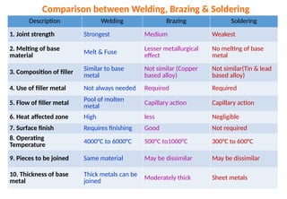
Description Welding BrazingSoldering
1. Joint strength Strongest Medium Weakest
2. Melting of base
material Melt & Fuse
Lesser metallurgical
effect
No melting of base
metal
3. Composition of filler
Similar to base
metal
Not similar (Copper
based alloy)
Not similar(Tin & lead
based alloy)
4. Use of filler metal Not always needed Required Required
5. Flow of filler metal
Pool of molten
metal Capillary action Capillary action
6. Heat affected zone High less Negligible
7. Surface finish Requires finishing Good Not required
8. Operating
Temperature
4000°C to 6000°C 500°C to1000°C 300°C to 600°C
9. Pieces to be joined Same material May be dissimilar May be dissimilar
10. Thickness of base
metal
Thick metals can be
joined Moderately thick Sheet metals
Comparison between Welding, Brazing & Soldering
75.
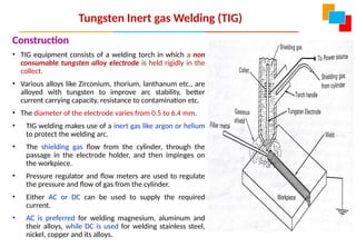
Tungsten Inert gasWelding (TIG)
Construction
• TIG equipment consists of a welding torch in which a non
consumable tungsten alloy electrode is held rigidly in the
collect.
• Various alloys like Zirconium, thorium, lanthanum etc., are
alloyed with tungsten to improve arc stability, better
current carrying capacity, resistance to contamination etc.
• The diameter of the electrode varies from 0.5 to 6.4 mm.
• TIG welding makes use of a inert gas like argon or helium
to protect the welding arc.
• The shielding gas flow from the cylinder, through the
passage in the electrode holder, and then impinges on
the workpiece.
• Pressure regulator and flow meters are used to regulate
the pressure and flow of gas from the cylinder.
• Either AC or DC can be used to supply the required
current.
• AC is preferred for welding magnesium, aluminum and
their alloys, while DC is used for welding stainless steel,
nickel, copper and its alloys.
76.
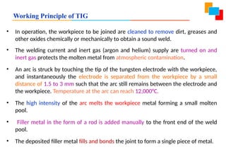
Working Principle ofTIG
• In operation, the workpiece to be joined are cleaned to remove dirt, greases and
other oxides chemically or mechanically to obtain a sound weld.
• The welding current and inert gas (argon and helium) supply are turned on and
inert gas protects the molten metal from atmospheric contamination.
• An arc is struck by touching the tip of the tungsten electrode with the workpiece,
and instantaneously the electrode is separated from the workpiece by a small
distance of 1.5 to 3 mm such that the arc still remains between the electrode and
the workpiece. Temperature at the arc can reach 12,000°C.
• The high intensity of the arc melts the workpiece metal forming a small molten
pool.
• Filler metal in the form of a rod is added manually to the front end of the weld
pool.
• The deposited filler metal fills and bonds the joint to form a single piece of metal.
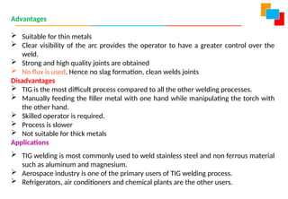
Advantages
Suitable forthin metals
Clear visibility of the arc provides the operator to have a greater control over the
weld.
Strong and high quality joints are obtained
No flux is used. Hence no slag formation, clean welds joints
Disadvantages
TIG is the most difficult process compared to all the other welding processes.
Manually feeding the filler metal with one hand while manipulating the torch with
the other hand.
Skilled operator is required.
Process is slower
Not suitable for thick metals
Applications
TIG welding is most commonly used to weld stainless steel and non ferrous material
such as aluminum and magnesium.
Aerospace industry is one of the primary users of TIG welding process.
Refrigerators, air conditioners and chemical plants are the other users.
79.
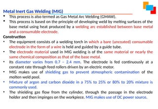
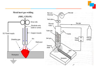
Metal Inert GasWelding (MIG)
This process is also termed as Gas Metal Arc Welding (GMAW).
This process is based on the principle of developing weld by melting surfaces of the
base metal using heat produced by a welding arc established between base metal
and a consumable electrode.
Construction
• The equipment consists of a welding torch in which a bare (uncoated) consumable
electrode in the form of a wire is held and guided by a guide tube.
• The electrode material used in MIG welding is of the same material or nearly the
same chemical composition as that of the base metal.
• Its diameter varies from 0.7 – 2.4 mm. The electrode is fed continuously at a
constant rate through feed rollers driven by an electric motor.
• MIG makes use of shielding gas to prevent atmospheric contamination of the
molten weld pool.
• Mixture of argon and carbon dioxide in a 75% to 25% or 80% to 20% mixture is
commonly used.
• The shielding gas flow from the cylinder, through the passage in the electrode
holder and then impinges on the workpiece. MIG makes use of DC power source.
81.
Working Principle ofMIG
The workpiece to be joined are cleaned to remove dust, grease and other
oxides, chemically or mechanically to obtain a sound weld.
The tip of the electrode is also cleaned with a wire brush.
The control switch provided in the welding torch is switched ON to
initiate the electric power, shielding gas the wire feed.
An arc is struck by touching the tip of the electrode with the
workpiece, and instantaneously the electrode is separated from the
workpiece by a small distance of 1.5 to 3 mm such that the arc still
remains between the electrode and the workpiece.
The high intensity of the arc melts the workpiece metal forming a small
molten pool.
At the same time, the tip of the electrode also melts and combines
with the molten metal of the workpiece thereby filling the gap
between the two workpieces.
The deposited metal upon solidification bonds the joint to form a
single piece of metal.
82.
Advantages of MIG
MIG welding is fast and economical
The electrode and inert gas are automatically fed. This reduces the burden
on the operator.
Weld deposition rate is high due to continuous wire feed
No flux is used. Hence, no slag formation
Thin and thick metals can be welded
Process can be automated
Disadvantages of MIG:
Equipment is costlier
Dross and porosity (gas entrapment in weld pool) are the most prevalent
quality problems in this process.
Applications:
Used extensively in sheet metal industry, and automobile industries.
83.
Heat Transfer Applications
Reviewof modes of Heat Transfer; Automobile Radiators; Condensers and
evaporators of refrigeration systems; Cooling of Electrical and Electronic
Devices; Active, Passive, and Hybrid Cooling.
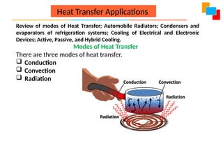
Modes of Heat Transfer
There are three modes of heat transfer.
Conduction
Convection
Radiation
84.
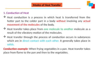
1. Conduction ofHeat
Heat conduction is a process in which heat is transferred from the
hotter part to the colder part in a body without involving any actual
movement of the molecules of the body.
Heat transfer takes place from one molecule to another molecule as a
result of the vibratory motion of the molecules.
Heat transfer through the process of conduction occurs in substances
which are in direct contact with each other. It generally takes place in
solids.
Conduction example: When frying vegetables in a pan. Heat transfer takes
place from flame to the pan and then to the vegetables.
Modes of Heat Transfer
85.
2. Convection ofHeat
In this process, heat is transferred in the liquid and gases from a
region of higher temperature to a region of lower temperature.
Convection heat transfer occurs partly due to the actual movement of
molecules or due to the mass transfer.
For example. Heating of milk in a pan.
3. Radiation of Heat
It is the process in which heat is transferred from one body to another
body without involving the molecules of the medium.
Radiation heat transfer does not depend on the medium.
For example: In a microwave, the substances are heated directly without
any heating medium.
Modes of Heat Transfer
86.
Heat Transfer Applications
•Heat should be continuously removed from the engine while it is
running.
• Basically there are two types in which cooling of the engine is
done
1.Air cooling
2.Liquid cooling
87.
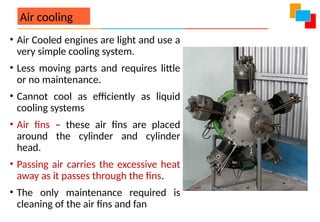
Air cooling
• AirCooled engines are light and use a
very simple cooling system.
• Less moving parts and requires little
or no maintenance.
• Cannot cool as efficiently as liquid
cooling systems
• Air fins – these air fins are placed
around the cylinder and cylinder
head.
• Passing air carries the excessive heat
away as it passes through the fins.
• The only maintenance required is
cleaning of the air fins and fan
88.
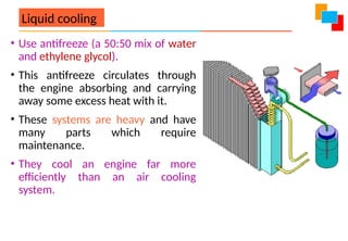
Liquid cooling
• Useantifreeze (a 50:50 mix of water
and ethylene glycol).
• This antifreeze circulates through
the engine absorbing and carrying
away some excess heat with it.
• These systems are heavy and have
many parts which require
maintenance.
• They cool an engine far more
efficiently than an air cooling
system.
89.
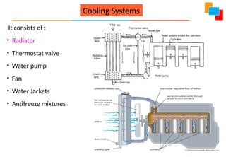
Cooling Systems
It consistsof :
• Radiator
• Thermostat valve
• Water pump
• Fan
• Water Jackets
• Antifreeze mixtures
90.
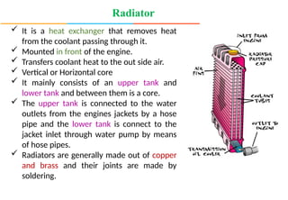
Radiator
It isa heat exchanger that removes heat
from the coolant passing through it.
Mounted in front of the engine.
Transfers coolant heat to the out side air.
Vertical or Horizontal core
It mainly consists of an upper tank and
lower tank and between them is a core.
The upper tank is connected to the water
outlets from the engines jackets by a hose
pipe and the lower tank is connect to the
jacket inlet through water pump by means
of hose pipes.
Radiators are generally made out of copper
and brass and their joints are made by
soldering.
91.
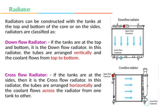
Radiator
Radiators can beconstructed with the tanks at
the top and bottom of the core or on the sides.
radiators are classified as:
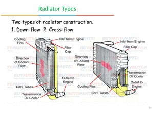
Down flow Radiator: - If the tanks are at the top
and bottom, it is the Down flow radiator. In this
radiator, the tubes are arranged vertically and
the coolant flows from top to bottom.
Cross flow Radiator: - If the tanks are at the
sides, then it is the Cross flow radiator. In this
radiator, the tubes are arranged horizontally and
the coolant flows across the radiator from one
tank to other.
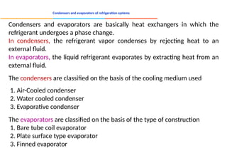
Condensers and evaporatorsof refrigeration systems
Condensers and evaporators are basically heat exchangers in which the
refrigerant undergoes a phase change.
In condensers, the refrigerant vapor condenses by rejecting heat to an
external fluid.
In evaporators, the liquid refrigerant evaporates by extracting heat from an
external fluid.
The condensers are classified on the basis of the cooling medium used
1. Air-Cooled condenser
2. Water cooled condenser
3. Evaporative condenser
The evaporators are classified on the basis of the type of construction
1. Bare tube coil evaporator
2. Plate surface type evaporator
3. Finned evaporator
94.
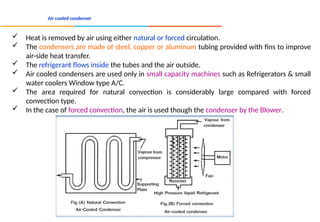
Air cooled condenser
Heat is removed by air using either natural or forced circulation.
The condensers are made of steel, copper or aluminum tubing provided with fins to improve
air-side heat transfer.
The refrigerant flows inside the tubes and the air outside.
Air cooled condensers are used only in small capacity machines such as Refrigerators & small
water coolers Window type A/C.
The area required for natural convection is considerably large compared with forced
convection type.
In the case of forced convection, the air is used though the condenser by the Blower.
95.
Water cooled condenser
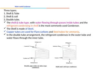
Threetypes:
1. Shell & Tube
2. Shell & coil
3. Double tube.
The shell & tube type, with water flowing through passes inside tubes and the
refrigerant condensing in shell is the most commonly used Condenser.
The Shell is made of Steel.
Copper tubes are used for Fluro carbons and Steel tubes for ammonia.
In the double tube arrangement, the refrigerant condenses in the outer tube and
water flows through the inner tube.
96.
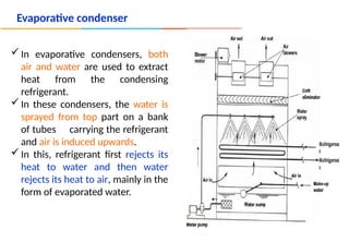
Evaporative condenser
In evaporativecondensers, both
air and water are used to extract
heat from the condensing
refrigerant.
In these condensers, the water is
sprayed from top part on a bank
of tubes carrying the refrigerant
and air is induced upwards.
In this, refrigerant first rejects its
heat to water and then water
rejects its heat to air, mainly in the
form of evaporated water.
97.
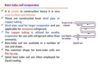
Bare tube coilevaporator
It is simple in construction hence it is very
easy to clean and defrost.
These are constructed from steel pipe or
copper tubing.
Steel pipe used for larger evaporator and are
applicable for ammonia refrigerant.
The copper tubing is utilized for smaller
evaporator for use with refrigerant other than
ammonia.
Bare-tube coil are available in a number of
size and shape.
The common shape for bare-tube coils are
flat zig-zag.
Spiral bare tube coil are often employed for
liquid cooling.
98.
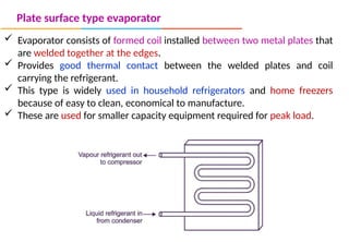
Plate surface typeevaporator
Evaporator consists of formed coil installed between two metal plates that
are welded together at the edges.
Provides good thermal contact between the welded plates and coil
carrying the refrigerant.
This type is widely used in household refrigerators and home freezers
because of easy to clean, economical to manufacture.
These are used for smaller capacity equipment required for peak load.
99.
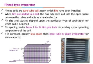
Finned type evaporator
Finned coils are bare-tube coils upon which fins have been installed.
When fins are added to a coil, the fins extended out into the open space
between the tubes and acts as a heat collector.
Fin size and spacing depend upon the particular type of application for
which coil is designed
Fin spacing varies from 1 to 14 fins per inch depending upon operating
temperature of the coil.
It is compact, occupy less space than bare tube or plate evaporator for
same capacity.