Introduction: Introduction:Streams in mechanical engineering and their
relevance/significance, role of mechanical engineers in solving the real case
problems (with examples), careers in mechanical engineering.
Realization of some of the engineering solutions through principles of
mechanical engineering(with a schematic diagram):
Energy conversion: Introduction and basic working principles of Pelton
Turbine and Centrifugal pump.
Vehicle systems: Identification of parts of vehicle systems such as steering
system, brake system, gear system, working principle of Power steering.
Flying machines: Classification, basic parts involved in drone making,
working principle of Drones.
Refrigeration and air conditioning principles.
Module-1
3.
Introduction to MechanicalEngineering
Mechanical Engineering is defined as the branch of engineering that deals with
the design, development, construction, and operation of mechanical systems and
tools.
It includes machines, tools, and equipment used in various industries, such as
transportation, manufacturing, power generation, Agriculture and medical
devices etc.
Mechanical engineers are also involved with the design, construction and
operations of all kinds of machinery.
They conceptualize design for any product to be manufactured.
Mechanical engineers are involved in almost every aspect of human existence
and welfare, including machines, cars and other vehicles, aircraft, power plants,
automobile parts, and manufacturing plants etc.
4.
Mechanical engineering hasplayed a significant role in the advancement of
modern society
• Power Generation: Mechanical engineers design and develop power-
generating machines such as internal combustion engines, gas turbines,
steam and wind turbines etc
• Heating and Cooling Systems: They design and develop heating, ventilation,
refrigeration and air conditioning systems for buildings and other structures.
• Transportation: Mechanical engineers are involved in designing and
developing transportation systems, including cars, trains, airplanes, steamers
and boats.
• Industrial Equipment: They design, develop and maintain industrial
equipment such as machine tools, robots, and conveyor systems & belts.
• Infrastructure: Mechanical engineers play a key role in the design and
maintenance of infrastructure, including buildings, bridges, roads, and
transportation systems.
Role of Mechanical Engineering in Industries and Society
5.
Emerging Trends andTechnologies in different sectors
Energy sector
Renewable Energy Integration:
Solar Power Advancements: Improvements in solar cell efficiency, new materials,
and innovative designs were enhancing the effectiveness of solar power.
Wind Power Innovation: Advances in turbine technology and offshore wind farms
were expanding the capabilities of wind energy.
Floating solar farms: These solar panels are installed on top of bodies of water,
which can help to conserve land and improve efficiency.
Battery Technologies: Ongoing developments in battery technology, including
solid-state batteries and advanced lithium-ion batteries, were increasing energy
storage capacity and efficiency.
6.
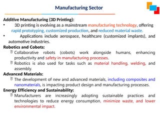
Additive Manufacturing (3DPrinting):
• 3D printing is evolving as a mainstream manufacturing technology, offering
rapid prototyping, customized production, and reduced material waste.
• Applications include aerospace, healthcare (customized implants), and
automotive industries.
Robotics and Cobots:
Collaborative robots (cobots) work alongside humans, enhancing
productivity and safety in manufacturing processes.
Robotics is also used for tasks such as material handling, welding, and
assembly.
Advanced Materials:
The development of new and advanced materials, including composites and
nanomaterials, is impacting product design and manufacturing processes.
Energy Efficiency and Sustainability:
Manufacturers are increasingly adopting sustainable practices and
technologies to reduce energy consumption, minimize waste, and lower
environmental impact.
Manufacturing Sector
7.
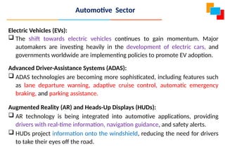
Electric Vehicles (EVs):
The shift towards electric vehicles continues to gain momentum. Major
automakers are investing heavily in the development of electric cars, and
governments worldwide are implementing policies to promote EV adoption.
Advanced Driver-Assistance Systems (ADAS):
ADAS technologies are becoming more sophisticated, including features such
as lane departure warning, adaptive cruise control, automatic emergency
braking, and parking assistance.
Augmented Reality (AR) and Heads-Up Displays (HUDs):
AR technology is being integrated into automotive applications, providing
drivers with real-time information, navigation guidance, and safety alerts.
HUDs project information onto the windshield, reducing the need for drivers
to take their eyes off the road.
Automotive Sector
8.
Aerospace Sector
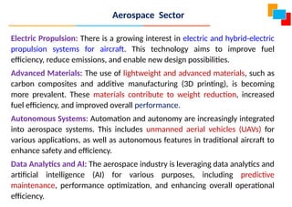
Electric Propulsion:There is a growing interest in electric and hybrid-electric
propulsion systems for aircraft. This technology aims to improve fuel
efficiency, reduce emissions, and enable new design possibilities.
Advanced Materials: The use of lightweight and advanced materials, such as
carbon composites and additive manufacturing (3D printing), is becoming
more prevalent. These materials contribute to weight reduction, increased
fuel efficiency, and improved overall performance.
Autonomous Systems: Automation and autonomy are increasingly integrated
into aerospace systems. This includes unmanned aerial vehicles (UAVs) for
various applications, as well as autonomous features in traditional aircraft to
enhance safety and efficiency.
Data Analytics and AI: The aerospace industry is leveraging data analytics and
artificial intelligence (AI) for various purposes, including predictive
maintenance, performance optimization, and enhancing overall operational
efficiency.
9.
Marine Sector
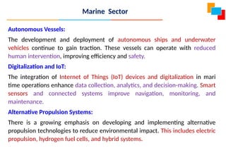
Autonomous Vessels:
Thedevelopment and deployment of autonomous ships and underwater
vehicles continue to gain traction. These vessels can operate with reduced
human intervention, improving efficiency and safety.
Digitalization and IoT:
The integration of Internet of Things (IoT) devices and digitalization in mari
time operations enhance data collection, analytics, and decision-making. Smart
sensors and connected systems improve navigation, monitoring, and
maintenance.
Alternative Propulsion Systems:
There is a growing emphasis on developing and implementing alternative
propulsion technologies to reduce environmental impact. This includes electric
propulsion, hydrogen fuel cells, and hybrid systems.
10.
Advanced Materials andCoatings:
The use of advanced materials and coatings improves the durability and
efficiency of marine structures, enhancing resistance to corrosion .
E-navigation and Electronic Charts:
Enhanced navigation systems and electronic charts improve accuracy and
safety in maritime navigation, reducing the risk of collisions and grounding
incidents.
Marine Sector
11.
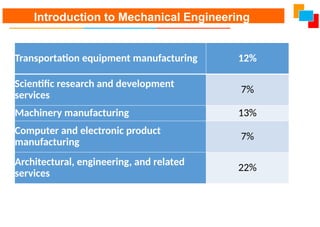
Transportation equipment manufacturing12%
Scientific research and development
services
7%
Machinery manufacturing 13%
Computer and electronic product
manufacturing
7%
Architectural, engineering, and related
services
22%
Introduction to Mechanical Engineering
12.
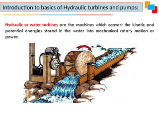
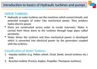
Hydraulic or waterturbines are the machines which convert the kinetic and
potential energies stored in the water into mechanical rotary motion or
power.
Introduction to basics of Hydraulic turbines and pumps:
13.
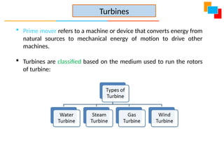
Prime moverrefers to a machine or device that converts energy from
natural sources to mechanical energy of motion to drive other
machines.
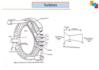
Turbines are classified based on the medium used to run the rotors
of turbine:
Turbines
WATER TURBINES
Hydraulicor water turbines are the machines which convert kinetic and
potential energies of water into mechanical power. They produce
hydro-electric power.
Dams are constructed across water to create reservoirs. Water is
carried from these dams to the turbines through large pipes called
penstocks.
Water drives the turbines and thus mechanical power is developed
which is converted into electrical power by the generators coupled
with the turbines.
Classification of Water Turbines
1. Impulse turbine (e.g. Pelton wheel, Girad, Banki, Jonval turbines etc.)
and,
2. Reaction turbine (Francis, Kaplan, Propeller, Thompson turbines).
Introduction to basics of Hydraulic turbines and pumps
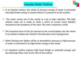
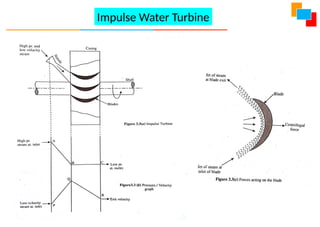
16.
o In animpulse turbine, the whole of pressure energy of water is converted
into high kinetic energy in nozzles before it is passed on to the turbine.
o The water comes out of the nozzle as a jet at high velocities. This high
velocity water jet is made to strike a series of curved vanes (blades)
mounted on the periphery of the rotor. The rotor is keyed to a shaft.
o The impulsive force of the jet exerted on the curved blades sets the wheel
in to rotation (rotates the wheel) in the direction of jet impingement.
o Water flowing over blades will be at atmospheric pressure as high pressure
of water is converted to its high kinetic energy in the nozzle.
o An impulsive turbine requires high head (height or potential energy) and
low discharge (flow rate) at the inlet of the turbine.
Impulse Water Turbine
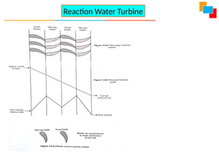
o A reactionwater turbine requires low head and high discharge or flow rate.
o The water passed onto the turbine will have both pressure and kinetic
energies.
o First, water passes through the guide blades which divert the water to enter
the blades called moving blades, mounted on the turbine.
o A part of pressure energy is converted in to kinetic energy of water which is
absorbed by the turbine wheel.
o Water leaving the turbine blades will be at a low pressure.
o The difference of pressure at the entry and the exit of the blades is called
reaction pressure. This pressure difference sets up the turbine wheel in to
rotation in the opposite direction
Reaction Water Turbine
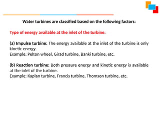
Water turbines areclassified based on the following factors:
Type of energy available at the inlet of the turbine:
(a) Impulse turbine: The energy available at the inlet of the turbine is only
kinetic energy.
Example: Pelton wheel, Girad turbine, Banki turbine, etc.
(b) Reaction turbine: Both pressure energy and kinetic energy is available
at the inlet of the turbine.
Example: Kaplan turbine, Francis turbine, Thomson turbine, etc.
22.
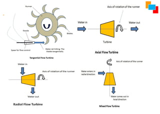
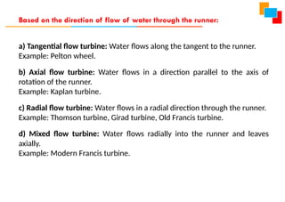
a) Tangential flowturbine: Water flows along the tangent to the runner.
Example: Pelton wheel.
b) Axial flow turbine: Water flows in a direction parallel to the axis of
rotation of the runner.
Example: Kaplan turbine.
c) Radial flow turbine: Water flows in a radial direction through the runner.
Example: Thomson turbine, Girad turbine, Old Francis turbine.
d) Mixed flow turbine: Water flows radially into the runner and leaves
axially.
Example: Modern Francis turbine.
Based on the direction of flow of water through the runner:
23.
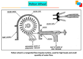
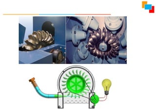
Pelton Wheel
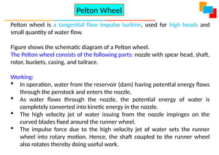
Pelton wheelis a tangential flow impulse turbine, used for high heads and small
quantity of water flow.
Pelton wheel isa tangential flow impulse turbine, used for high heads and
small quantity of water flow.
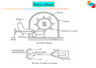
Figure shows the schematic diagram of a Pelton wheel.
The Pelton wheel consists of the following parts: nozzle with spear head, shaft,
rotor, buckets, casing, and tailrace.
Working:
In operation, water from the reservoir (dam) having potential energy flows
through the penstock and enters the nozzle.
As water flows through the nozzle, the potential energy of water is
completely converted into kinetic energy in the nozzle.
The high velocity jet of water issuing from the nozzle impinges on the
curved blades fixed around the runner wheel.
The impulse force due to the high velocity jet of water sets the runner
wheel into rotary motion. Hence, the shaft coupled to the runner wheel
also rotates thereby doing useful work.
Pelton Wheel
26.
Thus, thepotential energy of the water is converted into mechanical work.
After performing work, the water freely discharges to the tailrace. The work
produced at the output shaft is used to drive a generator to produce
electricity the electricity is then transmitted to a substation where
transformers increase voltage to allow transmission to homes, office, and
factories.
Advantages:
1) Simple in construction and easy maintenance.
2) To drive more power multiple jets (2 to 6) Pelton wheel may be used.
Disadvantages:
1) A lot of head loss occurs when the river discharge is low.
28.
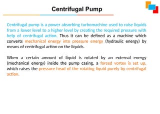
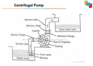
Centrifugal pump isa power absorbing turbomachine used to raise liquids
from a lower level to a higher level by creating the required pressure with
help of centrifugal action. Thus it can be defined as a machine which
converts mechanical energy into pressure energy (hydraulic energy) by
means of centrifugal action on the liquids.
When a certain amount of liquid is rotated by an external energy
(mechanical energy) inside the pump casing, a forced vortex is set up,
which raises the pressure head of the rotating liquid purely by centrifugal
action.
Centrifugal Pump
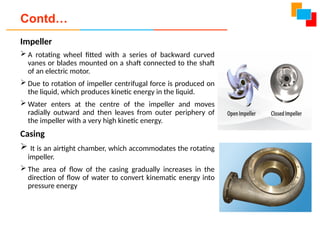
Impeller
A rotatingwheel fitted with a series of backward curved
vanes or blades mounted on a shaft connected to the shaft
of an electric motor.
Due to rotation of impeller centrifugal force is produced on
the liquid, which produces kinetic energy in the liquid.
Water enters at the centre of the impeller and moves
radially outward and then leaves from outer periphery of
the impeller with a very high kinetic energy.
Casing
It is an airtight chamber, which accommodates the rotating
impeller.
The area of flow of the casing gradually increases in the
direction of flow of water to convert kinematic energy into
pressure energy
Contd…
32.
Suction pipe
It isthe pipe through which water is lifted from the sump to the pump level.
Thus the pipe has its lower end dipped in the sump water and the upper
end is connected to the eye or the inlet of the pump.
At the lower end, a strainer and a foot-valve are also fitted.
Strainer
It is a screen provided at the foot of the suction pipe, it would not allow
entrance of the solid matters into the suction pipe which otherwise may
damage the pump.
Foot valve
It is a one direction valve provided at the foot of the suction pipe.
It permits flow only in one direction i.e. towards the pump. Foot valve
facilitates to hold the primed water in the suction pipe and casing before
starting the pump.
33.
Delivery pipe
Delivery pipeis used for delivery of liquid. One end connected to the
outlet of the pump while the other delivers the water at the required height
to the delivery tank. It consists of following components:
Delivery gauge
This gauge connected on the delivery side of the pump to measure the
pressure on the delivery side.
Delivery Valve
It is a gate valve on the delivery side of the pump to control the discharge
Shaft
It is a rotating rod supported by the bearings. It transmits mechanical
energy from the motor to the impeller.
Air Relieve Valve
These are the valves used to remove air from casing while priming.
34.
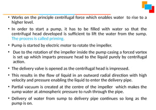
• Works onthe principle centrifugal force which enables water to rise to a
higher level.
• In order to start a pump, it has to be filled with water so that the
centrifugal head developed is sufficient to lift the water from the sump.
The process is called priming.
• Pump is started by electric motor to rotate the impeller.
• Due to the rotation of the impeller inside the pump casing a forced vortex
is set up which imparts pressure head to the liquid purely by centrifugal
action.
• The delivery valve is opened as the centrifugal head is impressed.
• This results in the flow of liquid in an outward radial direction with high
velocity and pressure enabling the liquid to enter the delivery pipe.
• Partial vacuum is created at the centre of the impeller which makes the
sump water at atmospheric pressure to rush through the pipe.
• Delivery of water from sump to delivery pipe continues so long as the
pump is on.
35.
Principle of refrigeration,Refrigeration effect, Ton of Refrigeration, COP, Refrigerants
and their desirable properties. Principles and Operation of Vapor Compression and
Vapor absorption refrigeration. Domestic and Industrial Applications of Refrigerator.
Refrigeration and Air-Conditioning
Refrigeration
“Refrigeration is defined as a method of reducing the temperature of a
system below that of the surroundings and maintaining it at the lower
temperature by continuously abstracting the heat from it.”
36.
Applications of Refrigeration
Foodprocessing, preservation and distribution
Chemical and process industries
Special Applications such as cold treatment of metals, medical,
construction etc.,
Comfort & Commercial air-conditioning
Industrial, such as in textiles, printing, manufacturing, photographic,
computer rooms, power plants, vehicular etc..
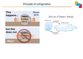
• Heat naturaltransfers from a region of higher temperature to lower
temperature.
• Vice versa is only possible by aid of external work as per 2nd
law of
thermodynamics.
• “It is impossible for a self acting machine, working in a cyclic
process, to transfer heat from a body at a lower temperature to
body at a higher temperature without the aid of an external
agency”.
Principle of Refrigeration
39.
Concepts related torefrigeration
1. Refrigeration effect:
In a refrigeration system, the rate at which the heat is absorbed in a cycle from the
interior refrigerating space to be cooled is called Refrigeration effect. Specified by
kJ/sec or kW
2. A Ton of refrigeration:
It is defined as the quantity of heat absorbed in order to form one ton of ice in 24
hours when the initial temperature of the water is 0°C.
1 Ton of refrigeration = 210 kJ/min = 3.5 kW
3. Ice making capacity:
It is the capacity of a refrigerating system to make solid ice beginning from water at
room temperature in one hour. Specified by kg/hr
40.
4. Coefficient ofPerformance (COP):
COP of a refrigerator is the ratio of heat absorbed from refrigerating
space to the work supplied.
5. Relative COP:
R-COP is the ratio of Actual COP to the Theoretical COP
41.
6. Refrigerant:
A Refrigerantis medium it continuously extracts the heat from the
space within the refrigerator which is to be kept cool at temperatures
less than the atmosphere and finally rejects to it to the surroundings.
Most Commonly used refrigerants:
7. Ammonia – Vapour Absorption Refrigerator
8. Carbon dioxide – Marine Refrigerators
9. Sulphur dioxide – House Hold Refrigerators
10. Methyl chloride – Small Scale Industrial Refrigeration and
House Hold Refrigerators
11. Freon 12 – Domestic Vapour Compression Refrigerators
12. Freon 22 – Air Conditioners
42.
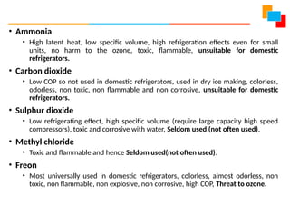
• Ammonia
• Highlatent heat, low specific volume, high refrigeration effects even for small
units, no harm to the ozone, toxic, flammable, unsuitable for domestic
refrigerators.
• Carbon dioxide
• Low COP so not used in domestic refrigerators, used in dry ice making, colorless,
odorless, non toxic, non flammable and non corrosive, unsuitable for domestic
refrigerators.
• Sulphur dioxide
• Low refrigerating effect, high specific volume (require large capacity high speed
compressors), toxic and corrosive with water, Seldom used (not often used).
• Methyl chloride
• Toxic and flammable and hence Seldom used(not often used).
• Freon
• Most universally used in domestic refrigerators, colorless, almost odorless, non
toxic, non flammable, non explosive, non corrosive, high COP, Threat to ozone.
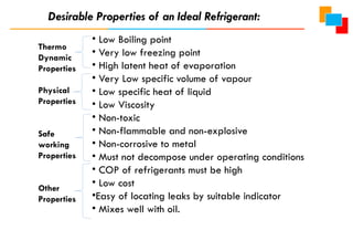
44.
• Low Boilingpoint
• Very low freezing point
• High latent heat of evaporation
• Very Low specific volume of vapour
• Low specific heat of liquid
• Low Viscosity
• Non-toxic
• Non-flammable and non-explosive
• Non-corrosive to metal
• Must not decompose under operating conditions
• COP of refrigerants must be high
• Low cost
•Easy of locating leaks by suitable indicator
• Mixes well with oil.
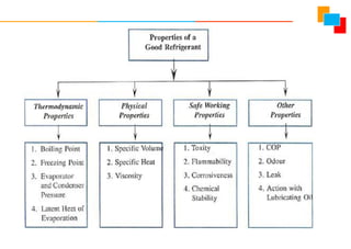
Desirable Properties of an Ideal Refrigerant:
Thermo
Dynamic
Properties
Physical
Properties
Safe
working
Properties
Other
Properties
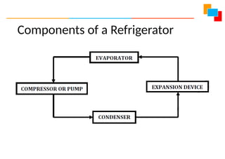
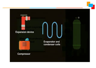
Vapor Compression Refrigeration(VCR) system
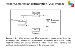
Process 1-2: High pressure and high temperature vapors coming from the
compressor get condense in the condenser by rejecting heat to the cooling
medium. Mostly the cooling medium is either air or water. Normally the
refrigerant at the exit of the condenser is the saturated liquid.
49.
Vapor Compression Refrigeration(VCR) system
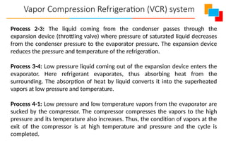
Process 2-3: The liquid coming from the condenser passes through the
expansion device (throttling valve) where pressure of saturated liquid decreases
from the condenser pressure to the evaporator pressure. The expansion device
reduces the pressure and temperature of the refrigeration.
Process 3-4: Low pressure liquid coming out of the expansion device enters the
evaporator. Here refrigerant evaporates, thus absorbing heat from the
surrounding. The absorption of heat by liquid converts it into the superheated
vapors at low pressure and temperature.
Process 4-1: Low pressure and low temperature vapors from the evaporator are
sucked by the compressor. The compressor compresses the vapors to the high
pressure and its temperature also increases. Thus, the condition of vapors at the
exit of the compressor is at high temperature and pressure and the cycle is
completed.
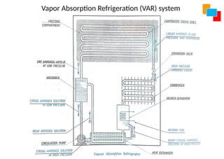
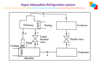
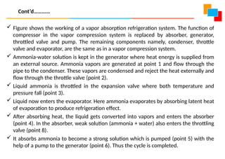
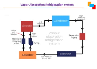
Figure showsthe working of a vapor absorption refrigeration system. The function of
compressor in the vapor compression system is replaced by absorber, generator,
throttled valve and pump. The remaining components namely, condenser, throttle
valve and evaporator, are the same as in a vapor compression system.
Ammonia-water solution is kept in the generator where heat energy is supplied from
an external source. Ammonia vapors are generated at point 1 and flow through the
pipe to the condenser. These vapors are condensed and reject the heat externally and
flow through the throttle valve (point 2).
Liquid ammonia is throttled in the expansion valve where both temperature and
pressure fall (point 3).
Liquid now enters the evaporator. Here ammonia evaporates by absorbing latent heat
of evaporation to produce refrigeration effect.
After absorbing heat, the liquid gets converted into vapors and enters the absorber
(point 4). In the absorber, weak solution (ammonia + water) also enters the throttling
valve (point 8).
It absorbs ammonia to become a strong solution which is pumped (point 5) with the
help of a pump to the generator (point 6). Thus the cycle is completed.
Cont’d…………
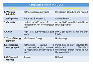
Comparison between VCR& VAR
Details Vapour Compression Vapour Absorption
1. Working
Principle
Refrigerant is compressed Refrigerant absorbed and heated
2. Refrigerant Freon -12 & Freon – 22 Ammonia (NH3)
3. Capacity Limited to 1000 tones of
refrigeration for a compressor
unit
Above 1000 tons (Not suitable for
small capacities)
4. C.O.P High (4-5), but very low at part
loads
Low , but same as full and part
loads
5. Type of Energy
supplied
Mechanical Energy Heat energy
6. Mechanical
energy input
Refrigerant vapour is
compressed to high pressure,
so mechanical energy input is
more
Pump has to only circulate the
refrigerant. Therefore,
mechanical energy input to run
the pump is less
7. Refrigerant
refilling
Simple Difficult
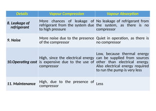
56.
Details Vapour CompressionVapour Absorption
8. Leakage of
refrigerant
More chances of leakage of
refrigerant from the system due
to high pressure
No leakage of refrigerant from
the system, as there is no
compressor
9. Noise
More noise due to the presence
of the compressor
Quiet in operation, as there is
no compressor
10.Operating cost
High, since the electrical energy
is expensive due to the use of
compressor
Low, because thermal energy
can be supplied from sources
other than electrical energy.
Also electrical energy required
to run the pump is very less
11. Maintenance High, due to the presence of
compressor
Less
57.
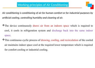
Working principles ofAir Conditioning
Air conditioning is conditioning of air for human comfort or for industrial purposes by
artificial cooling, controlling humidity and cleaning of air.
The device continuously draws air from an indoors space which is required to
cool, it cools in refrigeration system and discharge back into the same indoor
space.
This continuous cyclic process of drawing, cooling, and recirculation of the cooled
air maintains indoor space cool at the required lower temperature which is required
for comfort cooling or industrial cooling.
58.
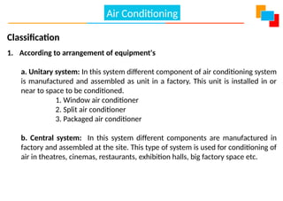
Classification
1. According toarrangement of equipment's
a. Unitary system: In this system different component of air conditioning system
is manufactured and assembled as unit in a factory. This unit is installed in or
near to space to be conditioned.
1. Window air conditioner
2. Split air conditioner
3. Packaged air conditioner
b. Central system: In this system different components are manufactured in
factory and assembled at the site. This type of system is used for conditioning of
air in theatres, cinemas, restaurants, exhibition halls, big factory space etc.
Air Conditioning
59.
2. According tothe purpose
1. Comfort air conditioning system
2. Industrial air conditioning system
3. According to season of year
1. Winter air conditioning system:
Air is heated and humidified
2. Summer air conditioning system:
Air is cooled and dehumidified
Air Conditioning
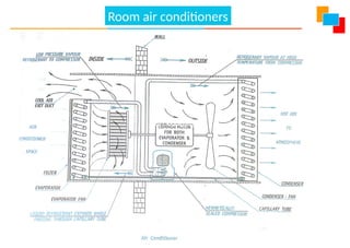
o Thehot air coming from room is flowing on the evaporator (cooling coil), the cooling coil
absorbs heat from air.
o Thus the air is cooled and dehumidified to meet the requirement comfort air conditioning in the
room.
o The filter clean the air coming from room before passes through the cooling coil.
o The flow of hot air (from room) and cooled air (to room) is taking place by the evaporator
blower.
o The refrigerating unit provides cooling effect at evaporator.
o The condenser fan circulates air on outside of condenser tubes, the refrigerant in condenser reject
heat to outside atmospheric air.
o Necessary fresh air is allowed to mix with the recalculated room air to meet the ventilation
requirement.
o The room temperature is controlled by a thermostat using on-off power supply to compressor
motor.
https://goo.gl/maps/JSuioDBoNuFdtk537
Room air conditioners
The applications ofair-conditioning are quite diverse. Applications and few
important areas are listed below.
Air-conditioning of theatres, cinema houses, Television studio
Hospitals, hotels, restaurants
Aircraft
Automobiles – buses, cars, Railway etc.
Offices, homes
Textile industry
Air-conditioning in photographic industry
Marine air-conditioning
Applications of Air-conditioning
64.
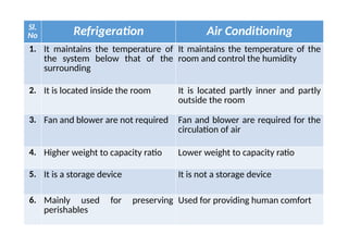
Sl.
No Refrigeration AirConditioning
1. It maintains the temperature of
the system below that of the
surrounding
It maintains the temperature of the
room and control the humidity
2. It is located inside the room It is located partly inner and partly
outside the room
3. Fan and blower are not required Fan and blower are required for the
circulation of air
4. Higher weight to capacity ratio Lower weight to capacity ratio
5. It is a storage device It is not a storage device
6. Mainly used for preserving
perishables
Used for providing human comfort
65.
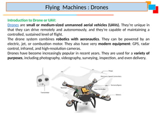
Introduction to Droneor UAV:
Drones are small or medium-sized unmanned aerial vehicles (UAVs). They’re unique in
that they can drive remotely and autonomously, and they’re capable of maintaining a
controlled, sustained level of flight.
The drone system combines robotics with aeronautics. They can be powered by an
electric, jet, or combustion motor. They also have very modern equipment: GPS, radar
control, infrared, and high-resolution cameras.
Drones have become increasingly popular in recent years. They are used for a variety of
purposes, including photography, videography, surveying, inspection, and even delivery.
Flying Machines : Drones
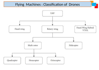
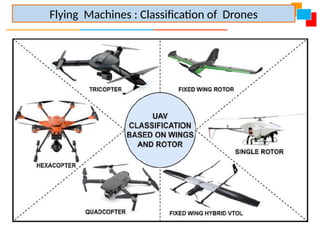
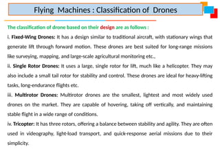
The classification ofdrone based on their design are as follows :
i. Fixed-Wing Drones: It has a design similar to traditional aircraft, with stationary wings that
generate lift through forward motion. These drones are best suited for long-range missions
like surveying, mapping, and large-scale agricultural monitoring etc.,
ii. Single Rotor Drones: It uses a large, single rotor for lift, much like a helicopter. They may
also include a small tail rotor for stability and control. These drones are ideal for heavy-lifting
tasks, long-endurance flights etc.
iii. Multirotor Drones: Multirotor drones are the smallest, lightest and most widely used
drones on the market. They are capable of hovering, taking off vertically, and maintaining
stable flight in a wide range of conditions.
iv. Tricopter: It has three rotors, offering a balance between stability and agility. They are often
used in videography, light-load transport, and quick-response aerial missions due to their
simplicity.
Flying Machines : Classification of Drones
69.
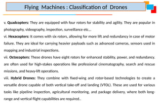
v. Quadcopters: Theyare equipped with four rotors for stability and agility. They are popular in
photography, videography, inspection, surveillance etc.,.
vi. Hexacopters: It comes with six rotors, allowing for more lift and redundancy in case of motor
failure. They are ideal for carrying heavier payloads such as advanced cameras, sensors used in
mapping and industrial inspections.
vii. Octocopters: These drones have eight rotors for enhanced stability, power, and redundancy.
are often used for high-stakes operations like professional cinematography, search and rescue
missions, and heavy-lift operations.
viii. Hybrid Drones: They combine with fixed-wing and rotor-based technologies to create a
versatile drone capable of both vertical take-off and landing (VTOL). These are used for various
tasks like pipeline inspection, agricultural monitoring, and package delivery, where both long-
range and vertical flight capabilities are required..
Flying Machines : Classification of Drones
70.
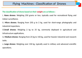
The classification ofdrone based on their weight are as follows :
i. Nano drones: Weighing 250 grams or less, typically used for recreational flying and
indoor surveillance.
ii. Micro drones: Ranging from 250 g to 2 kg, used for short-range photography and
industrial inspections.
iii.Small drones: Weighing 2 kg to 25 kg, commonly deployed in agricultural and
infrastructure applications.
iv. Medium drones: Ranging from 25 kg to 150 kg, used for heavier industrial and research
tasks.
v. Large drones: Weighing over 150 kg, typically used in military and advanced scientific
operations.
Flying Machines : Classification of Drones
71.
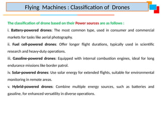
The classification ofdrone based on their Power sources are as follows :
i. Battery-powered drones: The most common type, used in consumer and commercial
markets for tasks like aerial photography.
ii. Fuel cell-powered drones: Offer longer flight durations, typically used in scientific
research and heavy-duty operations.
iii. Gasoline-powered drones: Equipped with internal combustion engines, ideal for long
endurance missions like border patrol.
iv. Solar-powered drones: Use solar energy for extended flights, suitable for environmental
monitoring in remote areas.
v. Hybrid-powered drones: Combine multiple energy sources, such as batteries and
gasoline, for enhanced versatility in diverse operations.
Flying Machines : Classification of Drones
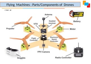
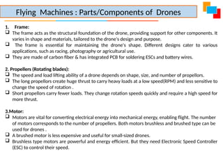
1. Frame:
Theframe acts as the structural foundation of the drone, providing support for other components. It
varies in shape and materials, tailored to the drone's design and purpose.
The frame is essential for maintaining the drone's shape. Different designs cater to various
applications, such as racing, photography or agricultural use.
They are made of carbon fiber & has integrated PCB for soldering ESCs and battery wires.
2. Propellers (Rotating blades):
The speed and load lifting ability of a drone depends on shape, size, and number of propellors.
The long propellors create huge thrust to carry heavy loads at a low speed(RPM) and less sensitive to
change the speed of rotation .
Short propellors carry fewer loads. They change rotation speeds quickly and require a high speed for
more thrust.
3.Motor:
Motors are vital for converting electrical energy into mechanical energy, enabling flight. The number
of motors corresponds to the number of propellers. Both motors brushless and brushed type can be
used for drones .
A brushed motor is less expensive and useful for small-sized drones.
Brushless type motors are powerful and energy efficient. But they need Electronic Speed Controller
(ESC) to control their speed.
Flying Machines : Parts/Components of Drones
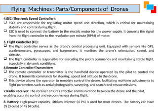
74.
4.ESC (Electronic SpeedController):
ESCs are responsible for regulating motor speed and direction, which is critical for maintaining
stability and control during flight.
ESC is used to connect the battery to the electric motor for the power supply. It converts the signal
from the flight controller to the revolution per minute (RPM) of motor.
5. Flight Controller (FC):
The flight controller serves as the drone's central processing unit. Equipped with sensors like GPS,
accelerometers, gyroscopes, and barometers, it monitors the drone's orientation, speed, and
altitude.
The flight controller is responsible for executing the pilot’s commands and maintaining stable flight,
especially in dynamic conditions.
6.Remote Controller/Transmitter:
The remote controller or transmitter is the handheld device operated by the pilot to control the
drone. It transmits commands for steering, speed and altitude to the drone.
This device allows the operator to remotely control the drone, facilitating real-time adjustments to
flight parameters such as aerial photography, surveying, and search-and-rescue missions.
7.Radio Receiver: The receiver ensures effective communication between the drone and the pilot,
enabling accurate control and responsiveness during flight.
8. Battery: High-power capacity, Lithium Polymer (Li-Po) is used for most drones. The battery can have
3S (3 cells) or 4S (4 cells).
Flying Machines : Parts/Components of Drones
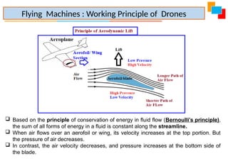
75.
Based onthe principle of conservation of energy in fluid flow (Bernoulli’s principle),
the sum of all forms of energy in a fluid is constant along the streamline.
When air flows over an aerofoil or wing, its velocity increases at the top portion. But
the pressure of air decreases.
In contrast, the air velocity decreases, and pressure increases at the bottom side of
the blade.
Flying Machines : Working Principle of Drones
76.
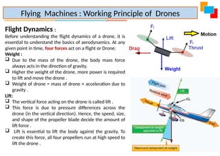
Flight Dynamics :
Beforeunderstanding the flight dynamics of a drone, it is
essential to understand the basics of aerodynamics. At any
given point in time, four forces act on a flight or Drone:
Weight :
Due to the mass of the drone, the body mass force
always acts in the direction of gravity.
Higher the weight of the drone, more power is required
to lift and move the drone .
Weight of drone = mass of drone × acceleration due to
gravity .
Lift:
The vertical force acting on the drone is called lift .
This force is due to pressure differences across the
drone (in the vertical direction). Hence, the speed, size,
and shape of the propeller blade decide the amount of
lift force .
Lift is essential to lift the body against the gravity, To
create this force, all four propellers run at high speed to
lift the drone .
Flying Machines : Working Principle of Drones
77.
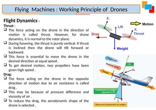
Flight Dynamics :
Thrust:
The force acting on the drone in the direction of
motion is called thrust. However, for drone
dynamics, it is normal to the rotor plane.
During hovering, the thrust is purely vertical. If thrust
is inclined then the drone will tilt forward or
backward.
This force is essential to move the drone in the
desired direction at equal speed .
To get desired motion, two propellers have been
given high speed .
Drag:
The force acting on the drone in the opposite
direction of motion due to air resistance is called
drag .
This may be because of pressure difference and
viscosity of air .
To reduce the drag, the aerodynamic shape of the
drone is selected .
Flying Machines : Working Principle of Drones
78.
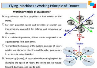
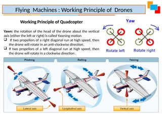
Working Principle ofQuadcopter
A quadcopter has four propellors at four corners of the
frame.
For each propeller, speed and direction of rotation are
independently controlled for balance and movement of
the drone .
In a traditional quadrotor, all four rotors are placed at an
equal distance from each other.
To maintain the balance of the system, one pair of rotors
rotates in a clockwise direction and the other pair rotates
in an anti-clockwise direction.
To move up (hover), all rotors should run at high speed. By
changing the speed of rotors, the drone can be moved
forward, backward, and side-to-side.
Flying Machines : Working Principle of Drones
79.
Working Principle ofQuadcopter
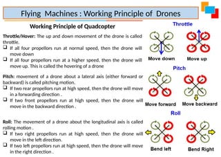
Throttle/Hover: The up and down movement of the drone is called
throttle.
If all four propellors run at normal speed, then the drone will
move down
If all four propellors run at a higher speed, then the drone will
move up. This is called the hovering of a drone
Flying Machines : Working Principle of Drones
Pitch: movement of a drone about a lateral axis (either forward or
backward) is called pitching motion.
If two rear propellors run at high speed, then the drone will move
in a forwarding direction .
If two front propellors run at high speed, then the drone will
move in the backward direction .
Roll: The movement of a drone about the longitudinal axis is called
rolling motion .
If two right propellors run at high speed, then the drone will
move in the left direction.
If two left propellors run at high speed, then the drone will move
in the right direction .
80.
Working Principle ofQuadcopter
Yawn: the rotation of the head of the drone about the vertical
axis (either the left or right) is called Yawning motion
If two propellors of a right diagonal run at high speed, then
the drone will rotate in an anti-clockwise direction.
If two propellors of a left diagonal run at high speed, then
the drone will rotate in a clockwise direction .
Flying Machines : Working Principle of Drones
81.
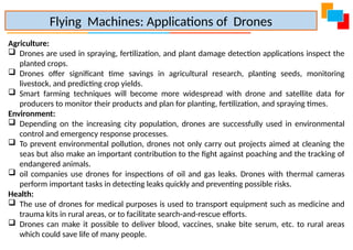
Agriculture:
Drones areused in spraying, fertilization, and plant damage detection applications inspect the
planted crops.
Drones offer significant time savings in agricultural research, planting seeds, monitoring
livestock, and predicting crop yields.
Smart farming techniques will become more widespread with drone and satellite data for
producers to monitor their products and plan for planting, fertilization, and spraying times.
Environment:
Depending on the increasing city population, drones are successfully used in environmental
control and emergency response processes.
To prevent environmental pollution, drones not only carry out projects aimed at cleaning the
seas but also make an important contribution to the fight against poaching and the tracking of
endangered animals.
oil companies use drones for inspections of oil and gas leaks. Drones with thermal cameras
perform important tasks in detecting leaks quickly and preventing possible risks.
Health:
The use of drones for medical purposes is used to transport equipment such as medicine and
trauma kits in rural areas, or to facilitate search-and-rescue efforts.
Drones can make it possible to deliver blood, vaccines, snake bite serum, etc. to rural areas
which could save life of many people.
Flying Machines: Applications of Drones
82.
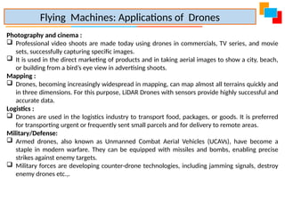
Photography and cinema:
Professional video shoots are made today using drones in commercials, TV series, and movie
sets, successfully capturing specific images.
It is used in the direct marketing of products and in taking aerial images to show a city, beach,
or building from a bird’s eye view in advertising shoots.
Mapping :
Drones, becoming increasingly widespread in mapping, can map almost all terrains quickly and
in three dimensions. For this purpose, LiDAR Drones with sensors provide highly successful and
accurate data.
Logistics :
Drones are used in the logistics industry to transport food, packages, or goods. It is preferred
for transporting urgent or frequently sent small parcels and for delivery to remote areas.
Military/Defense:
Armed drones, also known as Unmanned Combat Aerial Vehicles (UCAVs), have become a
staple in modern warfare. They can be equipped with missiles and bombs, enabling precise
strikes against enemy targets.
Military forces are developing counter-drone technologies, including jamming signals, destroy
enemy drones etc.,.
Flying Machines: Applications of Drones
83.
Vehicle systems: SteeringSystem
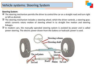
Steering System:
The steering mechanism permits the driver to control the car on a straight road and turn right
or left as desired.
The steering mechanism includes a steering wheel, which the driver controls, a steering gear,
which converts rotary motion of steering wheel in to straight line motion and steering
linkages.
In modern cars, the manually operated steering system is assisted by power and is called
power steering. The electric power drawn from the battery or hydraulic power is used.
84.
Functions of SteeringSystem:
It provides directional stability to the vehicle when moving in a straight (ahead)
direction.
It provides perfect steering condition, i.e., perfect rolling motion of the wheels at all
times.
It facilitates straight ahead recovery after completion of turn.
It controls the wear and tear of the tyre.
It is used to turn the vehicle as per the will of the driver.
It converts the rotary motion of the steering wheel into angular displacement of the
front wheel.
It multiplies the effort of the driver to ease operation.
It absorbs road shocks and prevents them from reaching the driver.
Vehicle systems: Steering System
85.
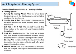
Functionality of /Components of / working Principle
of Steering System:
Turning the Steering Wheel: When the driver turns
the steering wheel, the steering column transmits this
motion to the steering box.
Steering Box Action: The steering box converts the
rotational motion into linear motion, which moves
the link rod.
Link Rod to Track Rod: The link rod transmits this
linear motion to the track rod, which is connected to
both wheels.
Track Rod Synchronization: The track rod ensures
that both wheels move in the same direction and by
the same amount when the steering wheel is turned.
Steering Arm Movement: The steering arm transfers
the motion from the track rod to the stub axle, which
causes the wheels to rotate.
Wheels Turning: The stub axle allows the wheels to
turn left or right, steering the vehicle in the desired
direction
Vehicle systems: Steering System
86.
Power Steering System:
Apower steering system uses a power source (hydraulic pressure or electric motor) to assist the
driver in turning the vehicle's steering wheel, making maneuvering much more comfortable and
requiring less physical strength compared to manual steering.
Types of Power Steering Systems:
Hydraulic Power Steering (HPS): Uses hydraulic pressure generated by a pump driven by the
engine. Pressurized fluid helps move components in the steering mechanism, reducing
steering effort.
Electric Power Steering (EPS): Utilizes an electric motor for assistance instead of hydraulic
fluid. The electric motor provides variable assistance based on vehicle speed and steering
demand, and it tends to be more energy-efficient.
Electro-Hydraulic Power Steering (EHPS): Combines both technologies; hydraulic power is
assisted by an electric pump.
Vehicle systems: Power Steering System
87.
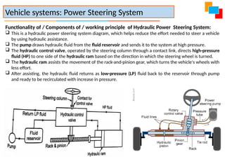
Functionality of /Components of / working principle of Hydraulic Power Steering System:
This is a hydraulic power steering system diagram, which helps reduce the effort needed to steer a vehicle
by using hydraulic assistance.
The pump draws hydraulic fluid from the fluid reservoir and sends it to the system at high pressure.
The hydraulic control valve, operated by the steering column through a contact link, directs high-pressure
fluid (HP) to one side of the hydraulic ram based on the direction in which the steering wheel is turned.
The hydraulic ram assists the movement of the rack-and-pinion gear, which turns the vehicle's wheels with
less effort.
After assisting, the hydraulic fluid returns as low-pressure (LP) fluid back to the reservoir through pump
and ready to be recirculated with increase in pressure.
Vehicle systems: Power Steering System
88.
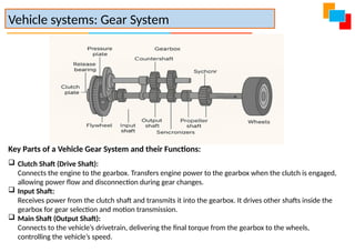
Key Parts ofa Vehicle Gear System and their Functions:
Clutch Shaft (Drive Shaft):
Connects the engine to the gearbox. Transfers engine power to the gearbox when the clutch is engaged,
allowing power flow and disconnection during gear changes.
Input Shaft:
Receives power from the clutch shaft and transmits it into the gearbox. It drives other shafts inside the
gearbox for gear selection and motion transmission.
Main Shaft (Output Shaft):
Connects to the vehicle’s drivetrain, delivering the final torque from the gearbox to the wheels,
controlling the vehicle’s speed.
Vehicle systems: Gear System
89.
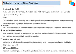
Countershaft (LayShaft):
Carries gears connected to the clutch shaft and main shaft, allowing power transmission and gear ratio
adjustment inside the gearbox.
Gears:
Circular toothed wheels of varying sizes that engage with other gears to change speed and torque enabling
acceleration, speed adjustment, and efficient power transmission.
Bearings:
Reduce friction for rotating components like shafts and gears, ensuring smooth operation of the gearbox.
Synchronizers (Synchromesh):
Assist smooth engagement of gears by matching the speed of gears before locking them together, reducing
gear clash and wear, especially in manual transmissions.
Gear Shift Lever and Fork:
Mechanism for selecting and engaging different gears as per driver’s command, usually controlled by the
driver via the gear stick.
Oil Pump and Oil Filter:
Systems for lubricating and cooling internal gearbox components to reduce wear and maintain performance.
Vehicle systems: Gear System
90.
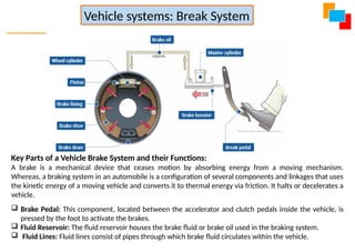
Key Parts ofa Vehicle Brake System and their Functions:
A brake is a mechanical device that ceases motion by absorbing energy from a moving mechanism.
Whereas, a braking system in an automobile is a configuration of several components and linkages that uses
the kinetic energy of a moving vehicle and converts it to thermal energy via friction. It halts or decelerates a
vehicle.
Brake Pedal: This component, located between the accelerator and clutch pedals inside the vehicle, is
pressed by the foot to activate the brakes.
Fluid Reservoir: The fluid reservoir houses the brake fluid or brake oil used in the braking system.
Fluid Lines: Fluid lines consist of pipes through which brake fluid circulates within the vehicle.
Vehicle systems: Break System
91.
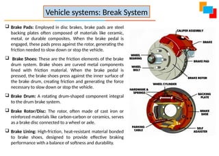
Brake Pads:Employed in disc brakes, brake pads are steel
backing plates often composed of materials like ceramic,
metal, or durable composites. When the brake pedal is
engaged, these pads press against the rotor, generating the
friction needed to slow down or stop the vehicle.
Brake Shoes: These are the friction elements of the brake
drum system. Brake shoes are curved metal components
lined with friction material. When the brake pedal is
pressed, the brake shoes press against the inner surface of
the brake drum, creating friction and generating the force
necessary to slow down or stop the vehicle.
Brake Drum: A rotating drum-shaped component integral
to the drum brake system.
Brake Rotor/Disc: The rotor, often made of cast iron or
reinforced materials like carbon-carbon or ceramics, serves
as a brake disc connected to a wheel or axle.
Brake Lining: High-friction, heat-resistant material bonded
to brake shoes, designed to provide effective braking
performance with a balance of softness and durability.
Vehicle systems: Break System