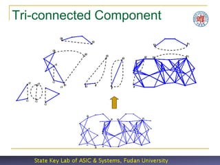
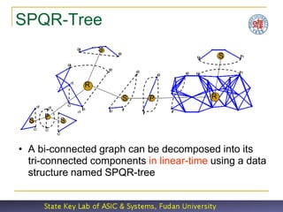
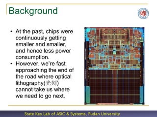
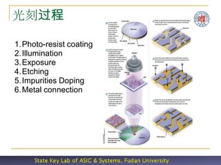
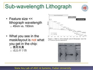
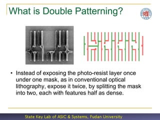
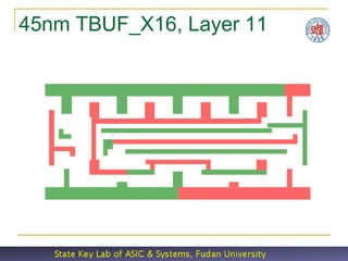
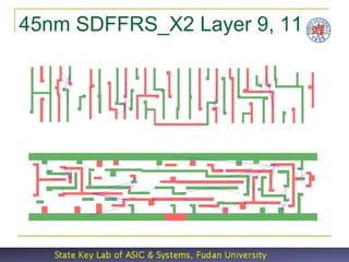
Multiple patterning is a class of technologies for manufacturing integrated circuits (ICs), developed for photolithography to enhance the feature density. The simplest case of multiple patterning is double patterning, where a conventional lithography process is enhanced to produce double the expected number of features. The resolution of a photoresist pattern is believed to blur at around 45 nm half-pitch. For the semiconductor industry, therefore, double patterning was introduced for the 32 nm half-pitch node and below. This presentation gives us an insight of why multiple patterning is an important to give us a better resolution below 32nm.
https://www.udemy.com/vlsi-academy
Usually, while drawing any circuit on paper, we have only one 'vdd' at the top and one 'vss' at the bottom. But on a chip, it becomes necessary to have a grid structure of power, with more than one 'vdd' and 'vss'. The concept of power grid structure would be uploaded soon. It is actually the scaling trend that drives chip designers for power grid structure.
Power gating is the main power reduction techniques for the static power. As long as technology scaling is taking place, static power becomes paramount important factor to the VLSI designs.Therefore Power gating is the recent power reduction technique that is actively in research areas.
This presentation discusses the Lambda based design rules for drawing the layouts. The spacing between ltwo layers, extent if of overlap, minimum dimensions of each layer etc are decided by the lambda based design rules. the separation between metal and poly, poly and diffusion , width of metal etc
In electronics, crosstalk is any phenomenon by which a signal transmitted on one circuit or channel of a transmission system creates an undesired effect in another circuit or channel. Crosstalk is usually caused by undesired capacitive, inductive, or conductive coupling from one circuit or channel to another.
Crosstalk is a significant issue in structured cabling, audio electronics, integrated circuit design, wireless communication and other communications systems.
Physical verification will verify that the post-layout netlist and the layout are equivalent. i.e. all connections specified in the netlist is present in the layout. This article explains physical verification.
TYPES OF PLACEMENT,GOOD PLACEMENT VS. BAD PLACEMENT ,ALGORITHMS, ASIC DESIGN FLOW DIAGRAM,DEFINITION OF PLACEMENT,TECHNIQUES USED FOR PLACEMENT,PLACEMENT TRENDS,SOLUTIONS
Reduced channel length cause departures from long channel behaviour as two-dimensional potential distribution and high electric fields give birth to Short channel effects.
Image segmentation is a computer vision task that involves dividing an image into multiple segments or regions, where each segment corresponds to a distinct object, region, or feature within the image. The goal of image segmentation is to simplify and analyze an image by partitioning it into meaningful and semantically relevant parts. This is a crucial step in various applications, including object recognition, medical imaging, autonomous driving, and more.
Key points about image segmentation:
Semantic Segmentation: This type of segmentation assigns each pixel in an image to a specific class, essentially labeling each pixel with the object or region it belongs to. It's commonly used for object detection and scene understanding.
Instance Segmentation: Here, individual instances of objects are separated and labeled separately. This is especially useful when multiple objects of the same class are present in the image.
Boundary Detection: Some segmentation methods focus on identifying the boundaries that separate different objects or regions in an image.
Methods: Image segmentation can be achieved through various techniques, including traditional methods like thresholding, clustering, and region growing, as well as more advanced techniques involving deep learning, such as using convolutional neural networks (CNNs) and fully convolutional networks (FCNs).
Challenges: Image segmentation can be challenging due to variations in lighting, color, texture, and object shape. Overlapping objects and unclear boundaries further complicate the task.
Applications: Image segmentation is used in diverse fields. For example, in medical imaging, it helps identify organs or abnormalities. In autonomous vehicles, it aids in identifying pedestrians, other vehicles, and obstacles.
Evaluation: Measuring the accuracy of segmentation methods can be complex. Metrics like Intersection over Union (IoU) and Dice coefficient are often used to compare segmented results to ground truth.
Data Annotation: Creating ground truth annotations for segmentation can be labor-intensive, as each pixel must be labeled. This has led to the development of datasets and tools to facilitate annotation.
Semantic Segmentation Networks: Deep learning architectures like U-Net, Mask R-CNN, and Deeplab have significantly improved the accuracy of image segmentation by effectively learning complex patterns and features.
Image segmentation plays a fundamental role in understanding and processing images, enabling computers to "see" and interpret visual information in ways that mimic human perception.
Image segmentation is a computer vision task that involves dividing an image into meaningful and distinct segments or regions. The goal is to partition an image into segments that represent different objects or areas of interest within the image. Image segmentation plays a crucial role in various applications, such as object detection, medical imaging, autonomous vehicles, and more.
For graphs of mathematical functions, see Graph of a function. For other uses, see Graph (disambiguation). A drawing of a graph. In mathematics graph theory is the study of graphs, which are mathematical structures used.In mathematics, and more specifically in graph theory, a tree is an undirected graph in which any two vertices are connected by exactly one path. In other words, any acyclic connected graph is a tree. A forest is a disjoint union of trees.
Initial Graphulo Graph Analytics Expressed in GraphBLAS:
GraphBLAS is an effort to define standard building blocks for graph algorithms in the language of linear algebra. Graphulo is a project to implement the GraphBLAS using Accumulo.
2. Background
• At the past, chips were
continuously getting
smaller and smaller,
and hence less power
consumption.
• However, we’re fast
approaching the end of
the road where optical
lithography(光刻)
cannot take us where
we need to go next.
4. Sub-wavelength Lithograph
• Feature size <<
lithograph wavelength
o 45nm vs. 193nm
• What you see in the
mask/layout is not what
you get in the chip:
o 图形失真
o 成品率下降
5. What is Double Patterning?
• Instead of exposing the photo-resist layer once
under one mask, as in conventional optical
lithography, expose it twice, by splitting the mask
into two, each with features half as dense.
6. Key Techniques
• Novel polygon cutting algorithm to reduce the
number of rectangles and the total cut-length.
• Novel dynamic priority search tree for plane-
sweeping.
• Decompose the underlying conflict graph into its
tri-connected components using SPQR-tree
• Graph-theoretical approach instead of ILP
o Recast the coloring problem as a T-join problem and
is then by solved by Hadlock’s algorithm
7. New Polygon Cutting Algorithm
• Allow minimal overlapping to
reduce the number of
rectangles, and hence to reduce
the number of conflicts.
• Limited support of diagonal line
segments
8. Dynamic Priority Search Tree
• In plane sweeping, events are frequently
“inserted” and “deleted” to the scan line.
• In our PST, all data are stored at the leaf
nodes of PST, making “insert” and “delete”
operations very fast (O(1) time for each tree
rotation). The payoff is that the “query”
operation will be little slower than the
traditional PST.
10. Conflict Detection
b
• Two rectangles are NOT conflict if
their distance is > b.
• Conflict: (A,C), (A,E), (E,B), (B,D),
but not (A,B), (A,D) (B,C)! A C
• Define: a polygon is said to be
rectilinearly convex if it is both x-
monotone and y-monotone.
• Rule: F
o (A,D) are not conflict because A-F-D
reconstructs a rectilinearly convex
polygon. E B D
o (A,C) are conflict because A-F-C
reconstructs a rectilinearly concave
polygon
12. Layout Splitting Problem
Formulation
• INSTANCE: Graph G = (V,E) and a weight function
w : E N
• SOLUTION: Disjoint vertex subsets V0 and V1
where V = V0 ∪ V1
• MINIMIZE: the total cost of edges whose end
vertices in same color.
• Note: the problem is linear-time solvable for bipartite
graphs, polynomial-time solvable for planar graphs,
but NP-hard in general.
• To reduce the problem size, graph partitioning
techniques could be used.
13. Bi-connected Graph
• A vertex is called a cut-vertex of G if removing it will
disconnect G.
• If no cut-vertex can be found in G, then the graph is called a bi-
connected graph.
• For example below, a and b are cut-vertices.
b
a
14. Bi-connected Components
• A connected graph can be decomposed into
its bi-connected components in linear-time.
• Each bi-connected component can be solved
independently without affecting the final sol’n.
• Question: Is it possible to further decompose
the graph?
15. Tri-connected Graph
• A pair of vertices is called a separation pair of a bi-connected
graph G if removing it will disconnect G.
• If no separation pair can be found, then the graph is called a tri-
connected graph.
• Eg below, {a,e}, {b,e}, {c,d}, {e,f}, {g,h} are separation pairs.
a e g h
d
c
b f
17. SPQR-Tree
S
S
R
S P R
P
S S
• A bi-connected graph can be decomposed into its
tri-connected components in linear-time using a data
structure named SPQR-tree
18.
19. Divide-and-Conquer Method
• Three basic steps:
o Divide a graph into its tri-connected components.
o Solve each tri-connected components in a
bottom-up fashion.
o Merge the solutions into a complete one in a top-
down fashion.
We calculate two possible solutions for each
components, namely {s, t} in same color and {s, t}
in opposite colors.
21. More Technical Details
• In Hadlock’s algorithm, voronoi graph instead
of complete graph is used.
• A brute-force method is used for solving the
maximum weighted planar subgraph problem
(could be improved)
27. Current Status of Our SW
• fft_all: 320K polygons1.3M rectangles
o Conflict graph construction within 1 minute
o Color assignment within 9 minutes
o Compare: 26 minutes for just displaying the result
using “eog”
o Note: Only g++ 3.4.5 was used, no advanced
compiler optimization has been done yet.
28. Conclusions
• Experiment results show that our method can
achieve 3-10X speedup
• We believe that it is a key to the success of
22nm process
• Unfortunately we didn’t have chance to try a
realistic 32/22nm layout yet
• because nearly everything is confidential
under 90nm
• Foundries may move to EUV if DPL fails.