Download as PDF, PPTX

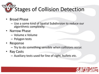

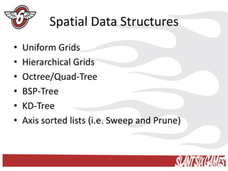


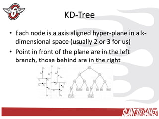


This document provides an overview of collision detection techniques, which are divided into broad, narrow, and response phases. The broad phase uses spatial data structures like grids, trees, and lists to reduce complexity by rejecting far-away object pairs. The narrow phase performs exact tests on close candidates output by the broad phase. Common representations are bounding volumes and hierarchies thereof. Popular algorithms apply the separating axis theorem to convex shapes. The response phase resolves collisions through impulses, forces, or rewinding. Ray casts are also discussed for line-of-sight checks.