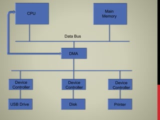
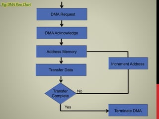
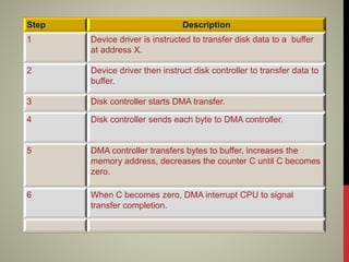
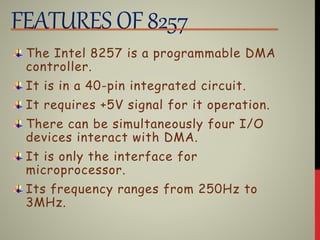
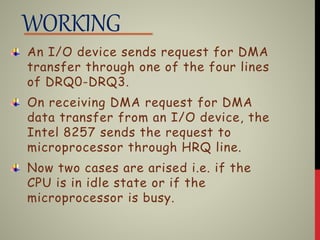
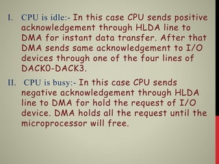
- By Sonali Soni
 DMA
 PIN DESCRIPTION
 FEATURES OF 8257
 WORKING
 SUMMARY
DMA
DMA(Direct Memory Access) is a feature
of computer system that allows certain
hardware subsystems to access main system
memory(RAM), independent of the central
processing unit(CPU).
It is deigned by Intel to transfer data at
the fastest rate.
Direct Memory Access needs a special
hardware called DMA controller that
manages the data transfer & arbitrates
access to the system bus.
CPU
Main
Memory
Data Bus
DMA
Device
Controller
Device
Controller
Device
Controller
USB Drive Disk Printer
DMA Request
DMA Acknowledge
Address Memory
Transfer Data
Transfer
Complete
Terminate DMA
Yes
Increment Address
No
Step Description
1 Device driver is instructed to transfer disk data to a buffer
at address X.
2 Device driver then instruct disk controller to transfer data to
buffer.
3 Disk controller starts DMA transfer.
4 Disk controller sends each byte to DMA controller.
5 DMA controller transfers bytes to buffer, increases the
memory address, decreases the counter C until C becomes
zero.
6 When C becomes zero, DMA interrupt CPU to signal
transfer completion.
INTE
L
8257
D0-D7
CS
Clk
Reset
A0-A3
A4-A7
I/OR
I/OW
Ready
HRQ
HLDA
Memr
Memw
VCC GND
DRQ0
DACK0
DRQ1
DACK1
DRQ2
DACK2
DRQ3
DACK3
AEN
ADSTB
TC
MARK
D0-D7:- These are bidirectional, data lines which are
used to interface the system bus with the internal bus
of DMA controller.
CS:- It is an active-low chip select line.
Clk:- It is a clock frequency signal which is required
for the internal operation of 8257.
Reset:- This signal is used to reset the DMA controller
by disabling all the DMA channels.
A0-A3:- These are the four least significant address
lines.
A4-A7:- These are the four most significant address
lines.
I/OR:-It is an active-low bidirectional tri-state input
line, which is used by the CPU to read internal
registers of 8257 in the slave mode. In the master
mode, it is used to read data from peripheral devices
during a memory write cycle.
I/OW:- It is an active-low bi-directional tri-state line,
which is used to perform Input/Output write operation.
Ready:- It is the input signal which makes DMA ready.
HRQ:- This signal is used to receive the hold request
signal from the output device.
HLDA:- It is the hold acknowledgement signal.
Memr:- It is the low memory read signal used to read
data during DMA read cycle.
Memw:- It is the active-low three state signal used to
write data during DMA write operation.
VCC:- It is the power signal required for the operation
of the circuit.
GND:- Ground.
DRQ0-DRQ3:- These are the four individual channel
DMA request inputs, which are used by the peripheral
devices for using DMA services.
DACK0-DACK3:- These are the active-low DMA
acknowledge lines, which updates the requesting
peripheral about the status of their request by the
CPU.
AEN(Address Latch Enable):- This signal is used to
disable the address bus/data bus.
ADSTB:- Address Data Bus.
TC:- It stands for ‘Terminal Count’, which indicates the
present DMA cycle to the present peripheral devices.
MARK:- The mark will be activated after each 128
cycles or integral multiples of it from the beginning.
FEATURES OF 8257
The Intel 8257 is a programmable DMA
controller.
It is in a 40-pin integrated circuit.
It requires +5V signal for it operation.
There can be simultaneously four I/O
devices interact with DMA.
It is only the interface for
microprocessor.
Its frequency ranges from 250Hz to
3MHz.
WORKING
An I/O device sends request for DMA
transfer through one of the four lines
of DRQ0-DRQ3.
On receiving DMA request for DMA
data transfer from an I/O device, the
Intel 8257 sends the request to
microprocessor through HRQ line.
Now two cases are arised i.e. if the
CPU is in idle state or if the
microprocessor is busy.
I. CPU is idle:- In this case CPU sends positive
acknowledgement through HLDA line to
DMA for instant data transfer. After that
DMA sends same acknowledgement to I/O
devices through one of the four lines of
DACK0-DACK3.
II. CPU is busy:- In this case CPU sends
negative acknowledgement through HLDA
line to DMA for hold the request of I/O
device. DMA holds all the request until the
microprocessor will free.
DMA helps to improve the speed of
transfer.
The microprocessor is freed from
involvement with the data transfer, thus
speeding up overall computer operation.
With DMA, CPU processing speed is also
increased.
At last we can conclude that with DMA the
efficiency and performance of a CPU is
increased.
DMA

DMA

  • 1.
  • 2.
     DMA  PINDESCRIPTION  FEATURES OF 8257  WORKING  SUMMARY
  • 3.
    DMA DMA(Direct Memory Access)is a feature of computer system that allows certain hardware subsystems to access main system memory(RAM), independent of the central processing unit(CPU). It is deigned by Intel to transfer data at the fastest rate. Direct Memory Access needs a special hardware called DMA controller that manages the data transfer & arbitrates access to the system bus.
  • 4.
  • 5.
    DMA Request DMA Acknowledge AddressMemory Transfer Data Transfer Complete Terminate DMA Yes Increment Address No
  • 6.
    Step Description 1 Devicedriver is instructed to transfer disk data to a buffer at address X. 2 Device driver then instruct disk controller to transfer data to buffer. 3 Disk controller starts DMA transfer. 4 Disk controller sends each byte to DMA controller. 5 DMA controller transfers bytes to buffer, increases the memory address, decreases the counter C until C becomes zero. 6 When C becomes zero, DMA interrupt CPU to signal transfer completion.
  • 7.
  • 8.
    D0-D7:- These arebidirectional, data lines which are used to interface the system bus with the internal bus of DMA controller. CS:- It is an active-low chip select line. Clk:- It is a clock frequency signal which is required for the internal operation of 8257. Reset:- This signal is used to reset the DMA controller by disabling all the DMA channels. A0-A3:- These are the four least significant address lines. A4-A7:- These are the four most significant address lines. I/OR:-It is an active-low bidirectional tri-state input line, which is used by the CPU to read internal registers of 8257 in the slave mode. In the master mode, it is used to read data from peripheral devices during a memory write cycle.
  • 9.
    I/OW:- It isan active-low bi-directional tri-state line, which is used to perform Input/Output write operation. Ready:- It is the input signal which makes DMA ready. HRQ:- This signal is used to receive the hold request signal from the output device. HLDA:- It is the hold acknowledgement signal. Memr:- It is the low memory read signal used to read data during DMA read cycle. Memw:- It is the active-low three state signal used to write data during DMA write operation. VCC:- It is the power signal required for the operation of the circuit. GND:- Ground.
  • 10.
    DRQ0-DRQ3:- These arethe four individual channel DMA request inputs, which are used by the peripheral devices for using DMA services. DACK0-DACK3:- These are the active-low DMA acknowledge lines, which updates the requesting peripheral about the status of their request by the CPU. AEN(Address Latch Enable):- This signal is used to disable the address bus/data bus. ADSTB:- Address Data Bus. TC:- It stands for ‘Terminal Count’, which indicates the present DMA cycle to the present peripheral devices. MARK:- The mark will be activated after each 128 cycles or integral multiples of it from the beginning.
  • 11.
    FEATURES OF 8257 TheIntel 8257 is a programmable DMA controller. It is in a 40-pin integrated circuit. It requires +5V signal for it operation. There can be simultaneously four I/O devices interact with DMA. It is only the interface for microprocessor. Its frequency ranges from 250Hz to 3MHz.
  • 12.
    WORKING An I/O devicesends request for DMA transfer through one of the four lines of DRQ0-DRQ3. On receiving DMA request for DMA data transfer from an I/O device, the Intel 8257 sends the request to microprocessor through HRQ line. Now two cases are arised i.e. if the CPU is in idle state or if the microprocessor is busy.
  • 13.
    I. CPU isidle:- In this case CPU sends positive acknowledgement through HLDA line to DMA for instant data transfer. After that DMA sends same acknowledgement to I/O devices through one of the four lines of DACK0-DACK3. II. CPU is busy:- In this case CPU sends negative acknowledgement through HLDA line to DMA for hold the request of I/O device. DMA holds all the request until the microprocessor will free.
  • 14.
    DMA helps toimprove the speed of transfer. The microprocessor is freed from involvement with the data transfer, thus speeding up overall computer operation. With DMA, CPU processing speed is also increased. At last we can conclude that with DMA the efficiency and performance of a CPU is increased.